")
52896WA Advanced Diploma of Civil and Structural Engineering (Materials Testing)
Investigation of the properties of construction materials, the principles which…Read more")
Graduate Diploma of Engineering (Safety, Risk and Reliability)
The Graduate Diploma of Engineering (Safety, Risk and Reliability) program…Read more
Professional Certificate of Competency in Fundamentals of Electric Vehicles
Learn the fundamentals of building an electric vehicle, the components…Read more
Professional Certificate of Competency in 5G Technology and Services Overview
Learn 5G network applications and uses, network overview and new…Read more
Professional Certificate of Competency in Clean Fuel Technology - Ultra Low Sulphur Fuels
Learn the fundamentals of Clean Fuel Technology - Ultra Low…Read more
Professional Certificate of Competency in Battery Energy Storage and Applications
Through a scientific and practical approach, the Battery Energy Storage…Read more
52910WA Graduate Certificate in Hydrogen Engineering and Management
Hydrogen has become a significant player in energy production and…Read more
Professional Certificate of Competency in Hydrogen Powered Vehicles
This course is designed for engineers and professionals who are…Read more
This chapter covers key concepts including After Diversity Maximum Demand (ADMD), calculation of multiplier factor, testing and calibration, and correction factor
Fundamentals of Smart Metering – kWh and kVArh Meters
kWh and kVArh Meters
As households and businesses began getting electricity in the late 19th century, utility companies needed a way to calculate how much electricity their customers were using. The first electricity meter was invented in 1872. Some 14 years later, Thomas Edison developed a model using electrolysis to measure electricity usage.
This was soon replaced by meters that used induction. The induction-type meters were used around 1930. They used the theory of electromechanical induction to makes this device work. Three magnetic fields are in play; one generated by the permanent magnet (the poles of which are positioned around a metal disc), one proportional to the voltage and a third proportional to the current. Because voltage (in volts) multiplied by current (in amps) equals power (in watts), these forces act on the disc in such a way as to make it turn at a speed proportional to the power used (expressed in kilowatt hours).
Modern electricity meters operate by continuously measuring the instantaneous voltage (volts) and current (amperes) and finding the product of these to give instantaneous electrical power (watts) which is then integrated against time to give energy used (joules, kilowatt-hours etc). The meters fall into two basic categories, electromechanical and electronic and digital. We are going to discuss some of the kWh and kVArh meters which were used earlier than Smart meters in this chapter.
Learning objectives
- Principles of operation for various kWh & kVArh meters
- Calculation of multiplier factors
- kWh meter construction
- Construction of kVArh meters
- Various connection of kWh & kVArh meters
- Apparent, active and reactive power calculation
- kWh & kVArh meters testing, calibration and adjustments
Kilowatt-hour is the energy consumed by 1000 Watts in one hour. If 1kW (1000 watts) of an electrical equipment is operated for 1 hour, it would consume 1 kWh of energy (1 unit of electricity). Figure 1.1 shows picture of analog electricity meter and latest digital smart meter which we are going to discuss in next few chapters.

Figure 1.1
Analog electricity meter(left) and digital smart meter(right)
For billing purpose in a company, it is the amount of electrical units in kWh recorded in the plant over a month for billing purpose. The company is charged or billed based on kWh consumption. Let us understand following terms in brief.
Contract demand
The amount of electric power that a customer demands from utility in a specified interval is the contract demand. It is the amount of electric power that the consumer agreed upon with the utility. This would mean that utility has to plan for the specified capacity. The unit used for contract demand is kVA or kW.
Maximum demand
Maximum demand is the highest average kVA recorded during any one-demand interval within the month. The demand interval is normally 30 minutes, but may vary from utility to utility from 15 minutes to 60 minutes. The demand is measured using a tri-vector meter / digital energy meter.
Prediction of load
In order to know the methods of load prediction, some of the terms used in connection with power supply must be appreciated.
Connected load:
It is the nameplate rating of the apparatus installed on a consumer’s premises. The rating is mentioned in kW or kVA.
Demand factor:
It is the ratio of maximum demand to the connected load.

Load factor:
It is the ratio of average load to maximum load

The load factor is also defined as the ratio of the energy consumed during a given period to the energy, which would have been used if the maximum load had been maintained throughout that period. For example, load factor for a day (24 hours) will be given by:

kWh meter was designed to measure the electrical power used over a longer period of time. It measure power consumed in terms of thousands of watts. Electric power is priced at a certain rate per kWh.
One kilowatt-hour means you used 1000 watts of electric power for 1 hour. If the cost of power is 10 cents per kilowatt-hour and if you operate a 1000-watt iron for 1 hour, you will be billed for 10 cents. If you operate the iron for 6 hours, you will use 60 cents worth of electrical energy.
The kilowatt-hour is a motor type device that accumulates and displays the kilowatt-hour usage, which is then read by a meter reader and subtracted from the last reading to see how much, was used in the interval between meter readings.
A precise fraction of the current flowing in the circuit is diverted to operate the motor. The speed at which the motor turns is proportional to the current in the circuit, and, therefore, each revolution of the motor’s rotor corresponds to a given amount of current flowing through the circuit.
The counter is connected to the rotor and adds and displays the amount of power the circuit has carried based on the number of revolutions of the rotor. The counter is usually marked in kilowatt-hours (1,000 watt-hours).
Demand factor and diversity factors are the two terms used in calculating the loads in electrical systems. Demand factor is already been mentioned above.
Diversity factor:
It is the ratio of the sum of the individual maximum demands of the various subdivisions of a system, or part of a system, to the maximum demand of the whole system, or part of the system, under consideration. This is usually more than one.
When used in an electrical design these terms should be applied as follows.
The sum of the connected loads supplied by a feeder-circuit can be multiplied by the demand factor to determine the load used to size the components of the system. The sum of the maximum demand loads for two or more feeders is divided by the diversity factor for the feeders to derive the maximum demand load.
Given:
Consider four individual feeder-circuits with connected loads of 250 kVA, 200 kVA, 150 kVA and 400 kVA and demand factors of 90%, 80%, 75% and 85% respectively. Use a diversity factor of 1.5.
Solution:
Calculating demand for feeder-circuits
250 kVA x 90% = 225 kVA
200 kVA x 80% = 160 kVA
150 kVA x 75% = 112.5 kVA
400 kVA x 85% = 340 kVA
____________
837.5 kVA
The sum of the individual demands is equal to 837.5 kVA.
If the main feeder-circuit were sized at unity diversity: kVA = 837.5 kVA ÷ 1.00 = 837.5 kVA
The main feeder-circuit would have to be supplied by an 850 kVA transformer.
However, using the diversity factor of 1.5, the kVA = 837.5 kVA ÷ 1.5 = 558 kVA for the main feeder. For diversity factor of 1.5, a 600 kVA transformer could be used.
Note that a 600 kVA transformer can be used instead of an 850 kVA when applying the 1.5 diversity factor.
Although feeder-circuit conductors should have an ampacity sufficient to carry the load, the ampacity of the feeder-circuit need not always be equal to the total of all loads on all branch-circuits connected to it.
In some cases a “demand factor” may be applied to the total load. The demand factor permits a feeder-circuit ampacity to be less than 100% of the sum of all branch-circuit loads connected to the feeder.
Applying Demand Factor for General Lighting
The difference between calculating branch circuit loads and feeder-circuit loads is that a demand factor is not usually applied for a branch-circuit, but may be applied in the case of a feeder-circuit. The load on a service or feeder is the sum of all of the branch loads subject to their demand factors.
In hospitals, hotels, apartment complexes, and dwelling units, it is not likely that all of the lights and receptacles connected to every branch-circuit served by a service or feeder would be “on” at the same time. Therefore, instead of sizing the feeder to carry the entire load on all of the branches, a percentage can be applied to this total load, and the components sized accordingly.
A demand factor for lighting may be applied only for dwelling units, hospitals, hotels, motels, and warehouses. All other occupancies are calculated on a basis of total computed lighting wattage, and no demand factor is permitted.
Applying Demand Factor for Motors
There are, in some cases, motor installations where there may be a special situation in which a number of motors are connected to a feeder-circuit. Because of the particular application, certain motors do not operate together and the feeder-circuit conductors are permitted to be sized based on a historical demand factor.
For example, the authority having jurisdiction may grant permission to allow a demand factor of less than 100 percent if operation procedures, production demands, or the nature of the work is such that not all the motors are running at one time. An engineering study or evaluation of motor operation may provide information that will allow a demand factor of less than 100 percent.
For engineers and contractors, the demand factors are the most widely used on a regular basis. With the application of demand factors, smaller components can be utilized in the electrical system and greater savings can be passed on to the consumer. Due to the high cost of wiring, there is a need for designers to utilize these techniques more than ever before.
A meter that records energy in watt-hours or kilowatt-hours is called a watt-hour meter (kilowatt-hour meter). One of the most important requirements of an energy meter is that it should indicate a given amount of energy proportional to power and time.
Electrolytic Watt-Hour Meter
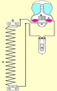
Figure 1.2
Electrolytic Watt-hour meter
Figure 1.2 shows a schematic of Electrolytic watt-hour meter. The abbreviations used are as follows:
- A: anode mercury
- B: glass fence
- C: Cathode
- D: negative terminal
- E: positive terminal
- K: shunt
- H: compensating resistance in series with tube.
Electrolytic watt-hour meter is mainly used for dc energy measurement, although it can be adapted by using a metal rectifier circuit and a current transformer, to function as an ac circuit for measuring kilo-volt ampere-hours.
The operating current is passed through a solution, causing electrolytic action. This gives a deposit of mercury or liberates gas proportional to the number of coulombs or ampere-hours passed through the meter, depending upon the meter type.
Let us assume that the voltage supply to the meter remains constant. The meter can be calibrated in kilo-watt hours; otherwise it is calibrated in ampere-hours. The body of electrolytic watt-hour meter includes a large amount of glass in their construction. Hence it requires fairly frequent inspection; however these meters are inexpensive to manufacture.
Clock Watt-Hour meter
Figure 1.3 shows the arrangement of clock watt-hour meter.

Figure 1.3 Clock Watt-hour meter
Two pendulums are shown in Figure1.3 at the bottom ends of which are placed two identical and circular coils C1 and C2. The pendulums are continuously driven by clockwork. The coils C1 and C2 are connected in series with each other and with a high resistance. They carry a current proportional to the line voltage. C3 and C4 are two current coils, placed beneath the pendulums, which are connected in series with the line and are wound in such a way that their magnetic fields are in the opposite direction.
In absence of current, the pendulums swing at the same rate but when current flows through C3 and C4, one of these coils exerts an accelerating force on one pendulum and the other coil exerts a retarding force on the other pendulum. The resulting difference in the time period of oscillation of two pendulums is arranged to give an indication of the dial register proportional to the energy passing through the meter.
This meter is suitable for both ac and dc energy measurements. It is comparatively free from temperature errors and stray fields.
Motor Watt-Hour Meter
Motor watt-hour meters are divided into two categories
- For dc energy measurement
- For ac energy measurement
The category for ac energy measurement is further classified into single phase and polyphase watt-hour meters.

Figure 1.4 Classification of motor watt-hour meter
The motor watt-hour meters which are used for ac energy measurement are also called induction watt-hour meter.

Figure 1.5 Motor watt-hour meter for dc energy measurement
A motor watt-hour meter for dc energy measure as shown in Figure 1.5 essentially consists of a small motor that is provided with a magnetic breaking mechanism.
The field coils of this meter consist of a few turns of heavy copper wire carrying the current under measurement, so that the field strength is directly proportional to the load current.
Following are the three main parts of motor meter for dc energy measurement:
- Rotating element
- Breaking system
- Clock or dial register
The rotating element is driven at a speed proportional to the energy or in some cases the quantity of electricity passing through the driving system. The breaking system ensures the proportionality between the energy and speed. It supplies the controlling action proportional to the speed of the rotor element.
Single phase induction watt-hour meter
Induction meters are simple in construction, provide high torque to weight ratio and are relatively inexpensive. This is the reason why induction meters are universally used for ac energy measurement. Figure 1.6 shows the schematic of single phase induction watt-hour meter.
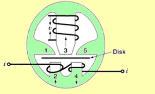
Figure 1.6 Single phase induction watt-hour meter for ac energy measurement
There are two current poles 2 and 4, which displaced from the voltage pole 3. When the power factor is unity, the flux фi from the current coils is in phase both with the voltage v and current i. The flux from the voltage coil is фv. This фv is in quadrature (90º phase displacement) with respect to фi. This is shown in Figure 1.7.
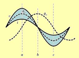
Figure 1.7 Phase diagram
Instant a:
At this time instant, both the current I and current flux фi are maximum, the voltage v is maximum and the voltage фv is minimum. The flux paths through the disk are from 2 to 1, from 2 to 3, from 3 to 4 and from 5 to 4.
Instant b:
At this time instant, both the current i and current flux фi are minimum, but the voltage v is minimum and the voltage flux фv is maximum.
Instant c:
At this time instant, both the current i and current flux фi are maximum and the voltage flux фv is minimum. The flux paths through the disks are from left to right. This causes eddy currents to be set up in the disk.
The reaction between the eddy currents and the field tends to move the disk in the direction of the field. While on load, the disk revolves continuously. This induces the emf (electromagnetic force) in it dynamically, as it cuts through the flux between the poles, in addition to the statically induced emfs due to the alternating flux in these poles.
Torque is produced due to dynamically induced eddy currents in the disk. This torque is negligible as compared to the operating torque produced by the statically induced currents.
Neglecting the effect of friction in the meter, and assuming that the active flux from the voltage pole lags 90º behind the impressed voltage, the operating or driving torque Td becomes proportional to the power in the circuit i.e.

Tr is the retarding torque due to eddy currents in proportional to the speed of revolution, N, of the disk, i.e.

In order to achieve steady state speed of the disk, Td must be equal to Tr; hence we can write
 This means that the speed of revolution of the disk is proportional to the power. The total number of revolutions, NT, over a time interval T is given as:
This equation shows that the total number of revolutions is proportional to the total energy supplied.
Poly Phase Induction Watt-Hour Meter
Polyphase energy can be measure by several single phase circuits that make up the polyphase circuit.
The energy delivered over a polyphase circuit is the total energy delivered over each equivalent single-phase circuit. Polyphase energy can be measured by connecting a single-phase watt-hour meter in each phase and then adding up readings of individual meters. This is not commercially practicable because:
- it requires too many meters;
- it takes much more time to read the meters; and
- it multiplies the chance of mistakes both in reading meters and in totaling meters.
The electrical industry has developed polyphase watt-hour meters.
The polyphase watt-hour meter is a combination of single-phase watt-hour meter stators that drive a rotor at a speed proportional to the total power in the circuit. The meter consists of a multi-stator motor, means for balancing the torques of all stators, a magnetic retarding system, a register, and compensating devices. These components are assembled on a frame and mounted on a base.
The operating principle of polyphase watt-hour meters, having any number of stators, is the same as single-phase watt-hour meters. Torque on each stator results from current in one set of electromagnetic coils and eddy currents induced in a disk, or disks, by current in the other set of coils. The torques of the several stators combines to give a resultant torque proportional to total power.
Because the same rules apply to measurement of both polyphase energy and polyphase power, principal parts of single-phase watt-hour meters can be combined for polyphase energy measurement, much as components of single-phase watt-meters are combined for polyphase power measurement. Blondel’s theorem applies to measurement of energy exactly as it does to measurement of power. A polyphase watt-hour meter is built with the number of elements necessary to satisfy Blondel’s theorem.
Figure 1.8 Poly phase induction watt-hour meter
Let us see following three types of kVArh meter:
- Hill-Schotter kVArh meter
- The spherical integrator types of kVArh meter
- The Landis and Gyr trivector meter
Hill-Schotter kVArh meter
This meter is essentially an induction type ampere hour meter with the registration mechanism designed for a particular system voltage. The system undergoes some voltage variation, to compensate for which a voltage compensating device is added to the system.
Principle of operation
- The main driving magnet M is a shaded pole electromagnet. This electromagnet is supplied by the load current.
- The electromagnet V is energized by the system voltage.
- The armature A is attached to spindle S switch carries two control weights W1 and W2, the balance weight W3 and the copper shading piece P.
- The movement of P is prevented by the control weight W2 until the system voltage exceeds the predetermined value.
- Weight W1 prevents its movement until the system voltage comes down the predetermined value.
- The effect of the shading piece P is to increase or decrease the driving torque according to whether the voltage is high or low.
- The breaking torque is developed due to a permanent magnet together with the main electromagnet.
Spherical Integrator type kVArh meter
This is an integrator type of meter because it essentially consists of both kWh and kVArh meters together with a mechanical device called spherical integrator. The spherical integrator functions to receive speeds proportional to kWh and kVArh and to transmit the resultant speed to the resistor mechanism. Thus the registration is proportional to kVArh.
The spherical integrator consists of a sphere driven by friction from two equal discs mechanically coupled to kWh and kVArh meter respectively.
The distance between the two discs are so adjusted that their points of contact with the sphere are separated by one quarter of the circumference of the sphere. The third friction disc C is driven by the sphere at a speed equal to the square root of the sum of squares of speeds of kWh and kVArh meters.
Principle of operation
Let us assume that NW and NR be the speeds in r.p.s. of discs W and R respectively. If the two speeds are same then the axis of rotation of the sphere XX’ will be horizontal and the twp contact points of the driving discs will move along a circumferential circle, on the sphere of diameter aa’ (=a) and bb’ (=b) which will be equal under this condition. But, in general, the two speeds are not same and the two diameters a and b are not equal.
Let N be the speed in r.p.s. of the sphere then the time taken in one revolution T = 1/N. during this period if the two driving discs rotate through angle θW and θR respectively then:


 A
A
nd the respective peripheral distances travelled by two discs are rθW and rθR and they must be equal to the peripherals of the circles of diameter a and b respectively i.e. 


Here r is the radius of the circle.
The contact point of the driven disc V with the sphere moves along the circle of diameter cc’ = (c) which is equal to the diameter of the sphere. If the radius of the disc V is also r then angle of rotation of V in time T is:


 Putting the values of a and b, we get:
 But
But  And
And 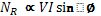

This shows that the registration of the mechanism attached to disc is kVArh.
Landis and Gyr trivector kVArh meter
This mechanism of transmitting the resultant of speeds of kWh and kVArh meters consists of five gear system, each of them driving a final drive at a particular power factor. Thus the combination of speeds is not exact at all power factors except at five power factors (1, 0.925, 0.707, 0.38, 0). But the errors are small. Also the drive is appositive at all points.
The final drive from each of the five gear system is taken to a ratchet-coupling linked to the kVArh register shaft. The ratchet-coupling is used so that the kVArh register is always driven by that gear system which has the maximum speed, while all other four gear systems remain ideal on the ratchet.
The gear system which correspond to unity and zero power factors are direct drives from kWh or kVArh meter, while the other gear systems are driven through differential gears. The planet wheels of the differential gears drive the final shaft linked through ratchet coupling. When the power factor changes by an appreciable amount, the drive shift to a different ratchet as a new shaft takes up the fastest running speed.
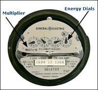
Figure 1.9 General Electric energy meter
If you have a multiplier other than 1, it will be indicated on the face of your meter. 4 dial meters may have a multiplier of 1 or 10 (indicated on the face of the meter)
In some cases, the energy meter does not have sufficient capacity to register the customer’s consumption. For this reason, some 4 dial meters are designed to record only a fraction of the actual kWh passing through the meter. These meter readings have to be multiplied by a specific factor, known as the multiplier, to determine your actual energy consumption.
Single phase two wire (1)
 Single phase 3 wire (2)
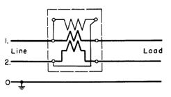 Single phase 2 wire meter using instrument transformer (3)
 Self contained meter (4)
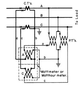
 Three phase 3 wire 2 element meter ( 2 PTs and CTs) (5)
Figure 1.10 Various connections
In three phase and four wire system, supply voltage is about 360 volts and 400 amps. The voltage and current must be reduced or stepped down by potential transformer (PT) and current transformer (CT) respectively before entering the meter. This is because maximum capacity of the meter is 120 volts and 5 amps used. The factor by which they are reduced is known as multiplier factor.
The voltage multiplier: 360 V ÷ 120V (PT ratio)
The current multiplier: 400A ÷ 5A = 80 (CT ratio)
Multiplier factor: 3 * 80 = 240
So the billing multiplier which is indicated on power meter is calculated as
Billing multiplier = PT ratio * CT ratio * meter multiplier
Let us discuss these terms in layman’s language
Apparent power – Apparent power is the power made available to us by electricity authority for which we pay tariff.
Active power – Active power is the power that the connected load consumes.
Reactive power – Reactive power is a nuisance power generated by the connected load in the system itself.
All the three are vector components.
Therefore in a common man’s language, active power is nothing but apparent power delivered at a factor known as ‘Power Factor’.
For AC systems voltage and current pulsate at the system frequency. Although AC voltage and current pulsate at same frequency, they peak at different time power is the algebraic product of voltage and current. Real power is the average of power over cycle and measured by volt-amperes or watt. The portion of power with zero average value called reactive power measured in volt-amperes reactive or vars.
The total power is called the apparent power (symbolized by the capital letter S) and measured by volt-amperes or VA. To describe the reactive power , imagine a person on trampoline , The person real power goes into moving horizontally across trampoline as it bounces , the effort the person expend to keep standing (represent reactive power Q ) during bouncing result no net forward motion(represent real power P) , but it’s necessary to walk on trampoline . The motion from trampoline always perpendicular to the direction the person is walking. So that the direction between P and Q 90 degree Out of phase.
Reactive power
The reactive power is defined in the IEEE Standard Dictionary 100-1996 under the energy “magner” as:

Equation (1)
where Vn and In are respectively the voltage and current rms values of the nth harmonics of the line frequency and  is the phase difference between the voltage and the current nth harmonics.
A convention is also adopted stating that the reactive energy should be positive when the current is leading the voltage (inductive load). In an electrical system containing purely sinusoidal voltage and current waveforms at a fixed frequency, the measurement of reactive power is easy and can be accomplished using several methods without errors. However, in the presence of non-sinusoidal waveforms, the energy contained in the harmonics causes measurement errors.
According to the Fourier theorem any periodic waveform can be written as a sum of sin and cosine waves. As energy meters deal with periodic signals at the line frequency both current and voltage inputs of a single phase meter can be described by:
![]()
![]()
where Vn and In are defined as in Equation 1.
Active power
The average active power is defined as:
![]()
The implementation of the active power measurement is relatively easy and is done accurately in most energy meters in the field.
Apparent power
The apparent power is the maximum real power that can be delivered to a load. As Vrms and Irms are the effective voltage and current delivered to the load,
Apparent power = Vrms • Irms
The correct implementation of the apparent energy measurement is bound by the accuracy of the rms measurements.
Reactive power calculation
Different methods can be used to calculate the reactive power. The theoretical definition of the reactive power is difficult to implement in an electronic system at a reasonable cost. It requires a dedicated DSP to process the Hilbert transform necessary to get a constant phase shift of 90° at each frequency. Several solutions have been developed to overcome this limitation. They can be categorized in three groups:
Method 1: Power triangle
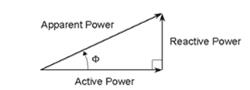
Figure 1.11 Power triangle
The Power triangle method is based on the assumption that the three energies, apparent, active and reactive, form a right-angle triangle as shown in Figure 1.11.
The reactive power :
![]()
can then be processed by estimating the active and apparent energies and applying.
Although this method gives excellent results with pure sinusoidal waveforms, noticeable errors appear in presence of harmonics.
Method 2: Time delay
A time delay is introduced to shift one of the waveforms by 90° at the fundamental frequency and multiply the two waveforms:


Figure 1.12 Reactive power calculation with time delay
where T is the period of the fundamental. In an electronic DSP system, this method can be implemented by delaying the samples of one input by the number of samples representing a quarter-cycle of the fundamental frequency (Fline) (Figure 1.12)
This method presents drawbacks if the line frequency changes and the number of samples no longer represent a quarter-cycle of the fundamental frequency. Significant errors are then introduced to the results (Table 1).
Method 3: Low-pass filter
A constant 90° phase shift over frequency with an attenuation of 20 dB/decade is introduced. This solution, which has been implemented by Analog Devices, can be realized with a single pole low-pass filter on one channel input (Figure 1.13).

Figure 1.13 Reactive power calculation with analog devices solution
If the cut-off frequency of the low-pass filter is much lower than the fundamental frequency, this solution provides a 90° phase shift at any frequency higher than the fundamental frequency. It also attenuates these frequencies by 20 dB/decade.
Similarly to method 2, this solution is susceptible to variations of the line frequency. However, a dynamic compensation of the gain attenuation with the line frequency can be achieved by evaluating the line period of the signal (Table 1).
Table 1
Error benchmark of different reactive energy calculation methods
| Test | Power triangle | Time delay | Low pass filter | |
| IEC 1268
Reference test |
Voltage and current
Input F: PF=0 |
Negligible | Negligible | Negligible |
| IEC 1268-
Frequency variation test |
Reference test
F +/- 2% and PF=0.87 |
Negligible | 5.4% | Negligible |
| IEC 1268-
Harmonic test |
Reference test +10% of the third harmonics on the current signal | 0.5% | Negligible | Negligible |
| IEC 1268
DC component test |
Reference test with half way rectified sin wave on the current input | Negligible | Negligible | Negligible |
| Reference test +10% of the third harmonics on voltage input and 20% of the third harmonics on current input
(
|
1.9% | 4% | 1% | |
 =
=  = 30° )
(The results from the three methods are compared to the results given by the true reactive energy measurement equation 1)
kWh meters are the only source to measure power consumption and generate revenue. Therefore it is essential to maintain and periodically verify accuracy of the kWh meters. It is also very essential to satisfy the consumer about the correctness of the meters.
It becomes necessary to calibrate kWh meter for number of reasons to determine the amount of error connected with its reading. Calibration is performed to minimize measurement errors and to increase the accuracy of the meter.Generally the manufacturer prints the meter constant on the meter.
A meter constant of about 800 means for 800 revolutions of the meter disc meter will record 1 kWh. The true value of energy consumed for fixed period of time is calculated.
For X revolutions the meter reads = 1 x X / 800 kWh
This measured value is calculated with true energy consumption and error is calculated. The percentage error against each reading is calculated and plotted on graph. Then it can be referred for further calculations.
![]()
= (Reading of kWh – wattmeter reading * time/wattmeter reading * time) * 100
Aside from the inherent errors due to variations in temperature, frequency, etc., which are factors of design, the most common causes of error within a meter are listed below and may be detected by inspection and then corrected.
Common causes:
- Dirt (on the disk; in the air gaps).
- Magnetic particles (in the permanent-magnet air gaps).
- Gummy oil and/or dirt in bearings.
- Broken jewels.
- Disk rubbing in air gap.
- Improper mesh of gears or dirty gearing.
- Improperly adjusted bearings.
- Vibration of the meter mounting.
- Creeping.
With the exception of 8 and 9 above, all other defects listed introduce friction and will cause the meter to register “slow.”
The error can be minimized by making certain adjustments in the meter.
1.1 Lag adjustment
It is assumed that angle between shunt magnetic flux and supply voltage is 90 . In actual practice it is difficult to achieve as magnetic flux lags behind supply voltage by few degrees less that 90. Therefore some arrangements are made to adjust mmf of the coil by adjusting resistance and arranging shading band.
1.2 Friction compensation
Friction at upper and lower support can cause errors particularly at light loads. Therefore it is necessary to arrange for small torque independent of the load on the meter which acts in the direction of rotation and equal in magnitude of the frictional torque.
1.3 Creeping
Slow but continuous rotation of the disc at no load is called creeping which is caused because of over compensation for friction. Creeping is minimized by drilling two holes opposite to each other to stop creep when the holes or slots reach a position directly under the potential coil pole. Observation of creep should, therefore, be based upon at least one complete revolution.
Test procedures and adjustments
Test equipment required:
- Rotating standard with potential switch and leads
- Load device – Resistance box, adjustable resistors, or phantom load
- Ammeter(s) of suitable ranges (not absolutely necessary when using resistance box or phantom load calibrated in amperes)
- Power-factor meter (not necessary, but very convenient not only for reading power factor but also for checking phase relation ships)
- Voltmeter (not necessary, but useful in checking connections)
- Phase-sequence indicator
- Power supply switch, fused
- Test leads and jumpers
- Tools for cleaning, jewel and pivot wrenches, etc.
- Jewel oil
Test connection diagrams
Test connection diagrams, shown in the figure 1.14 below shows methods of connecting the rotating standard and different types of load devices to various types of meters.


Figure 1.14 Phase sequence indicator
Types of meter tests
1) Routine Field
Meters are tested and adjusted by the series- parallel method. The only correction factor used is that of the rotating standard. Test points are 10, 20, 50, and 100-percent amps, 1.0 power factor and 100-percent test amps, 50 percent lagging power factor.
2) Precise Field
Meters are tested as in routine field tests except their adjustment includes correction for instrument transformer and test equipment errors.
3) Laboratory
The meter is tested in the laboratory. Tests include individual element as well as all elements combined. Tests are at 10, 20, 50, and 100-percent test amps, 1.0 power factor and 100 percent test amps, 50-percent power factor. After the tests and adjustments are completed, the meter is operated for 7 days if possible before returning to regular service.
Calibration
Two different, independent procedures for the calibrating rotating standards are possible.
- Direct comparison. The standard wattmeter is accurately calibrated by using several combinations of precisely measured d-c volts and currents. The rotating standards are then compared to the wattmeter. The procedure is slow, requires the skill of three or four technicians, and being replaced by the new electronic method. However, since the direct comparison method will be used for some short period of time, it is described in detail.
- Calibration of standard wattmeter. –

Figure 1.15 Calibration of standard wattmeter circuit diagram – direct comparison method
The standard watt meter is calibrated by using precisely measured values of d-c currents and voltages. The currents are 1.5, 2.5., and 5.0 amperes, while the voltage ranges selected vary between 100 and 125 to correspond with those experienced at the various revenue metering installations.
The test requires the services of four technicians: one to maintain precise voltage; one to maintain precise current; one to accurately read the standard wattmeter, and one to record data. The test circuit is shown in Figure 1.15. Using an exact value of current and voltage, five readings (with changes between each) are made on the wattmeter. The polarity of the circuit is then reversed and five additional readings are taken for the same current and voltage values. The average of the ten readings divided by the true watts (precise current times precise voltage) gives the correction factor for that combination of voltage and current. Similar tests and calculations are made for other current and voltage combinations, thus providing calibration curves for the standard wattmeter for several voltages. These are then used to calibrate the rotating standards.
Calibration of rotating standard.
The test circuit is shown in Figure 1.16 and the rotating standard is to be calibrated for 0.5, 2.5, and 5 amperes at unity power factor and 5 amperes at 50-percent lagging power factor for the range of voltages encountered in revenue meter testing.

Figure 1.16 Calibration of rotating standard
A series of five readings of the ammeter, voltmeter, standard wattmeter, rotating standard, and timer for each value of voltage, current, and power factor are required. Each measurement takes three minutes in order to secure better readings on the rotating standard. From these measurements, the following calculations are made in order to determine the correction factors for the rotating standard:

When readings are taken at the 50-percent lag power factor, an additional correction must be made to the true watts. This correction is due to the difference between ac-dc readings of the wattmeter. The corrections for this wattmeter are minus watts, and this is determined by multiplying the reading on the wattmeter by the percent difference from the NBS certificate. The minus watts are then subtracted from the true watts to give actual true watts for the 50-percent lag power factor.
2. Electronic or digital method
- Procedure involved.
The block diagram Figure 1.17 below shows the basic schematic for this method. The electronic wattmeter produces a d-c voltage output which is proportional to the input power. Adjustment is such that 600 watts input equals 1 volt d-c output. This output voltage is fed into a high accuracy frequency converter which converts the 1 volt d-c to 10,000 hertz. Thus :
:
Figure 1.17
Calibration of rotating standard- electronic method
- Calibration of the test equipment. Watt-hour calibrator is tested as a unit. Accurately measured values of dc voltage and current are fed into the converter (115v, 5 Amp, for 600 watts).
- The output of the watt converter is fed the voltage-to-frequency converter whose output is fed into the preset counter operating in the frequency counter mode. The average of the forward and reverse readings is determined. Then, average watt X 1000 over 600 equals the desired count.
Desired count = average watts x 1000 / 600
C.F. = Correction factor = Desired Count/Average Count
This correction factor must be combined with any other correction factors involved in the equipment such as CT correction factor, correction factors for the d-c potentiometer, etc., to arrive at the over-all correction factor for the watt-hour calibration standard. The preset counter has sufficient capacity to permit a check of 600 watts being measured for minutes (1800 watt-minutes).
kWh and kVArh meter are used to measure active and reactive power respectively. Traditional electrical meters only measure total consumption and as such provide no information of when the energy was consumed. Smart meters provide an economical way of measuring this information, allowing price setting agencies to introduce different prices for consumption based on the time of day and the season. A smart meter is an advanced meter that identifies consumption in more detail than a conventional meter and optionally, but generally, communicates that information via some network back to the local utility for monitoring and billing purposes.

Professional Certificate of Competency in Advanced TCP/IP-Based Industrial Networking
Designed for engineers and technicians who need practical knowledge in…Read more
Professional Certificate of Competency in Allen Bradley Controllogix / Logix5000 PLC Platforms
Designed for engineers and technicians who need practical knowledge in…Read more
Professional Certificate of Competency in Arc Flash Protection
Designed for engineers and technicians who work in the electrical…Read more
Professional Certificate of Competency in Chemical Engineering and Plant Design
Designed for engineers and technicians who need practical knowledge in…Read more
Professional Certificate of Competency in Circuit Breakers, Switchgear and Power Transformers
Designed for engineers and technicians who need practical knowledge regarding…Read more
Professional Certificate of Competency in Control Valve Sizing, Selection and Maintenance
Designed for engineers and technicians who need a solid understanding…Read more
Professional Certificate of Competency in Electrical Power System Fundamentals for Non Electrical Engineers
Designed for engineers and technicians who need to understand the…Read more
Professional Certificate of Competency in Electrical Power System Protection
Designed for engineers and technicians who need practical skills and…Read more")
Professional Certificate of Competency in Electrical Wiring Standards: AS/NZS 3000:2018 (Australia and New Zealand Only)
This professional development course is designed for engineers and technicians…Read more
Professional Certificate of Competency in Fundamental E & I Engineering for Oil and Gas Facilities
Designed for engineers and technicians who need to update their…Read more
Professional Certificate of Competency in Gas Turbine Engineering
Designed for engineers and technicians who need practical skills in…Read more
Professional Certificate of Competency in Hazardous Areas and Intrinsic Safety For Engineers and Technicians
Designed for engineers and technicians who need to understand the…Read more")
Professional Certificate of Competency in Heating, Ventilation and Air-Conditioning (HVAC)
Designed for engineers and technicians from a wide range of…Read more
Professional Certificate of Competency in IEC 61850 Based Substation Automation
Designed for engineers and technicians who need to understand the…Read more
Professional Certificate of Competency in Industrial Data Communications
Designed for engineers and technicians who need to understand how…Read more
Professional Certificate of Competency in Instrumentation, Automation and Process Control
Designed for engineers and technicians who need to gain practical…Read more
Professional Certificate of Competency in Machine Learning and Artificial Intelligence
This professional development course is designed for engineers and technicians…Read more
Professional Certificate of Competency in Mechanical Engineering
This professional development course is designed for engineers and technicians…Read more
Professional Certificate of Competency in Onshore and Offshore Pipeline Systems
Designed for engineers and technicians who need to gain an…Read more
Professional Certificate of Competency in Power Distribution
designed for engineers and technicians who need to gain a…Read more
Professional Certificate of Competency in Practical Machine Learning Using Python for Engineers and Technicians
Designed to use Python Programming to work with machine learning…Read more
Professional Certificate of Competency in Practical Python for Engineers and Technicians
Designed for engineers and technicians who need to understand the…Read more & SCADA Systems")
Professional Certificate of Competency in Programmable Logic Controllers (PLCs) & SCADA Systems
Designed for engineers and technicians who need to get practical…Read more
Professional Certificate of Competency in Project Management for Engineers & Technicians
This professional development course is designed for engineers and technicians…Read more
Professional Certificate of Competency in Safety Instrumentation Systems for Process Industries
Professional development course designed for engineers and technicians who want…Read more
Professional Certificate of Competency in Sewage and Effluent Treatment Technologies
Designed for engineers and technicians who need practical skills and…Read more
Professional Certificate of Competency in Structural Design for Non Structural Engineers
Professional development course designed for engineers and technicians who need…Read more")
Professional Certificate of Competency in Substation Design (Main Equipment)
Professional development course is designed for engineers and technicians who…Read more")
Professional Certificate of Competency in Substation Design (Control, Protection and Facility Planning)
Designed for engineers and technicians who need to gain practical…Read more
Professional Certificate of Competency in the Fundamentals of Process Plant Layout & Piping Design
Professional development course is designed for engineers and technicians who…Read more
Professional Certificate of Competency in Practical Mechanical Sealing
This professional development course is designed for engineers and technicians…Read more
Professional Certificate of Competency in Road Construction
This professional development course is designed for engineers and technicians…Read more
Professional Certificate of Competency in Specification and Technical Writing
Master the art of writing clear, accurate, and professional technical…Read more
Professional Certificate of Competency in Hydraulics and Pneumatics
Overview of all aspects related to the construction, design, operation,…Read more
Professional Certificate of Competency in Big Data and Analytics in Electricity Grids
This course explores the use of big data & data…Read more
Professional Certificate of Competency in Renewable Energy Systems
This course covers various renewable energy systems that are popular…Read more
Professional Certificate of Competency in Smart Grids
A smart grid is an electricity network that uses digital…Read more
Professional Certificate of Competency in Hydrogen Energy – Production, Delivery, Storage and Use
Hydrogen energy short course designed for engineers and professionals interested…Read more")
Professional Certificate of Competency in Building Information Modelling (BIM)
This professional development course is covering practical aspects of using…Read more
Professional Certificate of Competency in Industrial Internet of Things
Internet of Things (IoT) is the most sort after technology…Read more