")
52896WA Advanced Diploma of Civil and Structural Engineering (Materials Testing)
Investigation of the properties of construction materials, the principles which…Read more")
Graduate Diploma of Engineering (Safety, Risk and Reliability)
The Graduate Diploma of Engineering (Safety, Risk and Reliability) program…Read more
Professional Certificate of Competency in Fundamentals of Electric Vehicles
Learn the fundamentals of building an electric vehicle, the components…Read more
Professional Certificate of Competency in 5G Technology and Services Overview
Learn 5G network applications and uses, network overview and new…Read more
Professional Certificate of Competency in Clean Fuel Technology - Ultra Low Sulphur Fuels
Learn the fundamentals of Clean Fuel Technology - Ultra Low…Read more
Professional Certificate of Competency in Battery Energy Storage and Applications
Through a scientific and practical approach, the Battery Energy Storage…Read more
52910WA Graduate Certificate in Hydrogen Engineering and Management
Hydrogen has become a significant player in energy production and…Read more
Professional Certificate of Competency in Hydrogen Powered Vehicles
This course is designed for engineers and professionals who are…Read more
This manual covers the fundamental concepts and will provide you with a clear understanding of the design and engineering principles used in plant layout and piping design.
Practical Process Plant Layout and Piping Design
By N.S. Nandagopal (Nanda)
Rev 5.1
Website: www.idc-online.com
E-mail: idc@idc-online.com
IDC Technologies Pty Ltd
PO Box 1093, West Perth, Western Australia 6872
Offices in Australia, New Zealand, Singapore, United Kingdom, Ireland, Malaysia, Poland, United States of America, Canada, South Africa and India
Copyright © IDC Technologies 2011. All rights reserved.
First published 2009
All rights to this publication, associated software and workshop are reserved. No part of this publication may be reproduced, stored in a retrieval system or transmitted in any form or by any means electronic, mechanical, photocopying, recording or otherwise without the prior written permission of the publisher. All enquiries should be made to the publisher at the address above.
Disclaimer
Whilst all reasonable care has been taken to ensure that the descriptions, opinions, programs, listings, software and diagrams are accurate and workable, IDC Technologies do not accept any legal responsibility or liability to any person, organization or other entity for any direct loss, consequential loss or damage, however caused, that may be suffered as a result of the use of this publication or the associated workshop and software.
In case of any uncertainty, we recommend that you contact IDC Technologies for clarification or assistance.
Trademarks
All logos and trademarks belong to, and are copyrighted to, their companies respectively.
Acknowledgements
IDC Technologies expresses its sincere thanks to all those engineers and technicians on our training workshops who freely made available their expertise in preparing this manual.
Contents
Prelim i-x
1 Introduction to Process Plant Layout and Piping Design 1
1.1 Plant layout fundamentals 1
1.2 Procedures and workflow methods used in plant layout and piping design 6
1.3 Physical quantities and units in plant layout and piping design 9
1.4 Summary 12
Practical Exercise 1 13
2 Introduction to Chemical Processing Methods 15
2.1 Basic principles of chemical process technology 15
2.2 Process flow diagrams (PFDs) 20
2.3 Summary 27
Practical Exercise 2 28
3 Equipment Used in Process Plants 31
3.1 Introduction 31
3.2 Process equipment 32
3.3 Mechanical equipment 47
3.4 Summary 51
Practical Exercise 3 (Towers and Reactors) 53
4 Plant Layout and Plot Plans 55
4.1 Plant layout specifications 55
4.2 Plot plans 56
4.3 Summary 65
Practical Exercise 4 66
5 Piping and Instrumentation Diagrams (P&IDs), Control Valve Manifolds, Meter Runs 69
5.1 Piping and instrumentation diagrams (P&IDs) and their role in process plant layout and piping design 69
5.2 P&ID symbols and terminologies 70
5.3 Layout and components of control valve manifolds 76
5.4 Layout and components of flow meters 77
5.5 Summary 78
Practical Exercise 5 (P&IDs) 79
6 Plant Layout and Piping Design Documentation and Tools 81
6.1 Importance of documentation in plant layout and piping design 81
6.2 Equipment arrangement drawings 82
6.3 Equipment lists 84
6.4 Piping and instrumentation diagrams (P&IDs) 84
6.5 Piping line lists 84
6.6 Piping codes 86
6.7 Piping specification 89
6.8 Piping isometrics 91
6.9 Fabrication isos and bill of materials 94
6.10 Three dimensional (3D) models 96
6.11 Summary 98
Practical Exercise 6 99
7 Fundamentals of Piping 101
7.1 Fundamentals of piping 101
Practical Exercise 7 104
Practical Exercise 7 – Metric 107
8 Components of a Piping System 109
8.1 Fittings 109
8.2 Flanges 118
8.3 Valves 126
Practical exercises in Metric 133
8.4 Summary 139
9 Pipe Routing 141
10 Piping Materials 151
10.1 Introduction 151
10.2 Material classification system and specifications 152
10.3 Piping specifications 154
10.4 Material selection 154
10.5 Quality control and material certification 155
Appendix A Pipe Data and Fitting Dimensions 157
Post Course Test 173
This chapter provides a brief introduction to Process Plant Layout and Piping Design. The fundamental aspects of process plant layout and piping design are discussed. An overview of the procedures and workflow methods used in plant layout and piping design is also provided and the physical quantities and units commonly used are presented.
Learning objectives
- Understanding the fundamental aspects of process plants, plant layout and piping design.
- Understanding the procedures and the workflow methods used in designing process plants and piping systems.
- Understanding the physical quantities and units used in process plant layout and piping design.
1.1 Plant layout fundamentals
Process plants encompass all types of facilities involved in the chemical/physical processing of raw materials into desired finished products or intermediates for further processing. Examples of such processing facilities include the following:
- Refineries.
- Chemical/Petrochemical Plants.
- Fertilizer Plants.
- Offshore Processing Facilities.
- Power Plants.
- Pulp and Paper Mills.
- Food/Beverage Industries.
- Pharmaceutical Plants.
- Water Treatment Plants.
- Waste Treatment Facilities.
The processing facilities included in the preceding list play a vital role in meeting the basic needs of humanity. Therefore, a proper design, maintenance and operation of such facilities is necessary to ensure steady, dependable supply of materials and products required for comfortable and productive living in the contemporary modern world.
Process plants are complex facilities consisting of equipment, piping systems, instruments, electrical systems, electronics, computers and control systems. Figure 1.1 is a picture of a section of a refinery that illustrates the complexity of the equipment, piping and other entities.

A small section of a refinery showing equipment, piping system and other items.
The design of process plants is a complex team effort involving different disciplines of engineering: process (chemical), mechanical, piping, electrical, instrumentation, controls, materials and project. It also requires considerable management and coordination skills.
The objective is to design and construct a plant in a cost-effective manner that will meet the process requirements and client specifications and that will operate in a safe reliable manner. Other factors to be considered in the design of process plants are:
- Short design, engineering and construction schedules and getting the plant on stream as quickly as possible.
- Minimizing or even eliminating field rework, which significantly increases plant construction costs.
- Constructability.
- Maintainability.
- Operability.
- Satisfying environmental requirements.
- Minimizing costs.
Figure 1.2 illustrates the interaction and teamwork between different disciplines in the plant layout and piping design effort.

Plant Design and Piping Design Effort – Contributions from different disciplines
Tasks involved in plant layout and piping design
Plant Layout and Piping Design involve multiple tasks, which include:
- Development and refinement of “Plot Plans”. Plot plans are representations of precise location of equipment and their associated infrastructure (foundations, ladders, platforms etc.). Plot plans are developed taking into consideration process, client and safety requirements. Plant coordinates are used extensively in specifying equipment locations. Plot plans are discussed in more detail in Chapter 4.
- Establishing equipment nozzle locations. Nozzles are components of equipment that connect to pipe.
- Routing of pipes. This is a dynamic and iterative process until the equipment and nozzle locations are finalized.
- Designing equipment ancillaries such as foundations, platforms, and stairways.
- Location of safety equipment such as fire hydrants and safety showers.
- Being cognizant of the location of structures, instruments, control valves, electrical raceways and miscellaneous plant items while routing pipe.
The salient skills and qualities required for plant layout and piping design are as follows:
- Sufficient knowledge of the process being used including function of each equipment. This information is obtained from the process group in the form of “Process Flow Diagrams (PFDs)”. PFDs are discussed in detail in Chapter 2.
- Knowledge of the operating and maintenance procedures used for equipment.
- Common sense and attention to detail.
- Ability to think creatively to solve layout problems and challenges.
- Ability to think and visualize spatial relationships between plant items in three dimensions.
- Ability to effectively use computer tools such as 3D modeling software and pipe stress analysis software.
- Excellent communication skills.
- Ability to function effectively as a member of a multi-disciplinary project team.
- Effectively communicate and resolve layout issues and problems with project management.
- Ability to produce, maintain and update project drawings and documents.
- Awareness that conscientious, quality effort during the design and engineering phase can shorten project schedules resulting in economic benefits and client goodwill.
Data used in plant layout and piping design
Massive amounts of data is generated and used in plant layout and piping design. Proper management of plant data is necessary to ensure data accessibility and data integrity, which in turn contributes to the overall quality of the project. Plant data can be classified into three categories.
- Project data consists of information such as plant location, local codes and regulations, access roads, waterways, railways, seismic conditions, climate data (average temperature, wind speed and direction, and rainfall).
- Design and engineering data is internally generated during the design and engineering phases of the project. Examples of such data include equipment sizes, service conditions (temperature, pressure etc.), and mass flow rates.
- Vendor data consists of information provided by equipment vendors by means of vendor drawings and data sheets.
Rules of thumb for plant layout and piping design
The approach to plant layout and piping design can vary depending on the nature of the plant and the project. For example, the design philosophy for an offshore facility is quite different from that for an onshore chemical plant simply because of limited space available on offshore platforms. However, there are a few useful rules of thumb that can be followed.
- Knowledge and understanding of project requirements and project documents.
- Conservation of space and resources.
- Arrangement of equipment in a neat, organized manner taking into account process needs and safety.
- Attention to detail including adjacent equipment, supports and other items, which can cause potential clashes between piping and equipment/supports.
- Consideration of constructability, operability and maintainability of the plant.
- Routing of pipe in a neat, orderly and symmetrical manner keeping in mind the future needs of the plant.
- Avoiding excessive changes in elevations and directions.
- Ensuring consistency in design.
- Avoiding excessive amounts of relocations and revisions by “doing it right the first time”.
Common abbreviations used in plant layout and piping design
- N,S,E,W: North, South, East and West
- CL: Centerline
- El: Elevation
- TOS: Top of Steel
- BOP: Bottom of Pipe
- POS: Point of Support
- BBP: Bottom of Baseplate
- ISBL: Inside Battery Limits
- OSBL: Outside Battery Limits
- AG: Above Ground
- UG: Underground
- ϕ: Diameter
- OD: Outside Diameter of pipe
- ID: Inside Diameter of pipe
- TL: Tangent Line
- TYP: Typical
- PFD: Process Flow Diagram
- P&ID: Piping and Instrumentation Diagram
Abbreviations used in PFDs and P&IDs are explained in Chapters 2 and 5 respectively.
1.2 Procedures and workflow methods used in plant layout and piping design
Front end engineering and design: The complex task of designing and building process plants consists of several phases – design, engineering, procurement and construction. The design phase itself consists of conceptual design, design study and detailed design. The conceptual design phase starts with the Process Flow Diagram (PFD) and client specifications. The project scope is also defined during this phase. The working documents used during this phase are the PFD and the Conceptual Plot Plan. Based on the PFD, a large chemical plant or offshore production facility is sub-divided into several small, manageable areas. A Plot Plan is then generated for each area. Boundary limits for each area are specified using spatial coordinates. The boundaries are known as match lines and play an important role in combining the smaller areas. In offshore platforms, plot plans are generated for each deck of the platform. The outcome of the conceptual design phase is usually preliminary sizes and locations of major equipment, which results in the plot plan for use during the design study phase.
The design study phase plot plan is reviewed and discussed by the client and by the project disciplines. Vessel supports and ancillaries are located during this phase. Preliminary routing of major lines also takes place during this phase. The outcome of the design study phase is a final plot plan and a preliminary Piping & Instrumentation Diagram (P&ID). The P&ID contains details and specifications of all equipment, piping, fittings, instrumentation and control valves. The P&ID also contains references to detailed drawings of equipment. The P&ID serves as the primary reference document in communication between engineering and design personnel in all disciplines. Thus, the P&ID is an important working document in the design and engineering of process plants and piping systems. The final plot plan and the P&ID must be approved by all disciplines including safety and loss control.
The conceptual design and design study phases together constitute the Front End Engineering and Design (FEED) phase of the project. The P&ID, plot plans and elevations are used in building a three dimensional electronic model of the process plant. This 3-D model will contain all the components of the plant including equipment, piping, fittings, control stations and support structures. In recent years, the ability to build 3-D electronic models has been greatly enhanced due to advancements in computer hardware and software.
Detailed design and engineering: The FEED phase is followed by the detailed design and engineering phase where every piece of equipment and every component of piping systems is finalized and specified for procurement. During this phase, piping isometric drawings known as “Issued-For Design (IFD)” drawings are generated for analysis and comment by piping engineers and engineers from other disciplines whose input is required. The IFD drawings are pictorial representations of the piping system and allied components containing all dimensional information. Piping engineers primarily use the IFD drawings for the following purposes:
- Pipe Stress Analysis: The piping systems are analyzed for stress and load to ensure that the pipes are not overstressed (both under installed and operating conditions) and are adequately supported. In many cases, piping systems need to have enough flexibility to allow for thermal expansion. Pipe stress analysis also includes computing loads and stresses on equipment nozzles and ensuring that they are within the allowable limits specified by applicable standards and codes. Pipe stress analysis is performed with the aid of stress analysis software.
- Code compliance: The code that governs the design of piping systems for process plants is ASME B31.3: Process Piping. Piping engineers are responsible for interpreting the code using sound engineering judgment to ensure that the proposed design meets the code requirements.
- Piping material specifications: The piping engineer is responsible for specifying appropriate materials for the pipes. In accomplishing this task, the piping engineer takes into account operating conditions such as the pressure and temperature and also the chemical nature of the fluid being transported. Piping material specification is a very time consuming task but it is very important to specify the right material to ensure the safe and efficient operation of the plant.
The 3-D model is an extremely useful design tool that can be used by all disciplines during the detailed design and engineering phase. The 3-D model is constantly referenced during design review meetings and discussions. These meetings occur frequently and involve all the engineering disciplines and the client. The 3-D model is also useful in clash detection and interference checking. This process saves considerable money and effort by minimizing field rework and field rerouting of pipes. An engineering database is also generated as part of the electronic model. This database is useful in purchasing and procurement functions. As the design is reviewed and updated, so is the 3-D model.
After the detailed design and engineering phase, piping isometric fabrication drawings (also known as spool drawings) along with material specifications are issued for creating the required piping spools. Simultaneously, procurement lists are generated for fittings, instrumentation and other items in the piping system from the engineering database. The procurement lists are used for purchasing the items and contain all the information required to accomplish this task. The procurement lists are also known as “Bill of Materials (BOM)” or “Material Take-off”.
Foundations, structural members and major equipment are put in place using civil/structural drawings, equipment drawings, the 3-D model and other documents. Now the stage is set for the installation of the piping system. Drawings and documents known as “Issued for Construction (IFC)” are used for this purpose. Construction personnel assemble and install the piping system by using IFC drawings and documents.
Figure 1.3 illustrates the workflow methods used in process plant layout and piping design. It should be noted that workflow methods could vary depending on client and company preferences. It should also be noted that the entire process is iterative in nature. There is continuous interaction between the different phases of the project.

Procedures and Workflow Methods Used in Plant Layout and Piping Design
Organizations involved in providing standards and guidelines for plant layout and piping design
Some of the organizations that provide standards and guidelines for plant layout and piping design are listed here along with their web addresses.
- American Society for Mechanical Engineers (ASME): Publishes and updates codes for piping design. The code relevant to the design of piping systems is ASME B31.3 – 2004 Process Piping. (www.asme.org)
- Center for Chemical Process Safety (CCPS): Publishes documents and guidelines related to process safety. The focus is on preventing or mitigating catastrophic releases of chemicals, hydrocarbons, and other hazardous materials. CCPS has published guidelines for “Facility Siting and Layout”. (www.aiche.org/ccps)
- Construction Industry Institute (CII): Provides guidelines for cost effective and safe construction methods and has several publications on constructability. (www.construction-institute.org)
- Society of Piping Engineers and Designers (SPED): Promotes excellence and quality in the practice of piping engineering and design. SPED emphasizes education and training and has certification programs for piping designers. (www.spedweb.org)
- Occupational Safety and Health Administration (OSHA): Provides regulations and safety standards for the operation of process plants. (www.osha.gov)
- National Fire Protection Association (NFPA): Provides fire protection standards for process plants and for gas storage and handling. (www.nfpa.org)
1.3 Physical quantities and units in plant layout and piping design
The physical quantities and units used in plant layout and piping design are summarized in Table 1.1. The units are specified both in the SI System and in the US Customary System (USCS).
| Physical Quantity |
Symbol | SI System | USCS |
|---|---|---|---|
| Length | L | Meter (m) | Feet (ft) |
| Diameter | D | Millimeter (mm) | Inch (in) |
| Thickness | Δx | Millimeter (mm) | Inch (in) |
| Mass | m | Kilogram (kg) | Pound mass (lbm) |
| Time | t | Seconds (s) | Seconds (sec) |
| Temperature | T | Degree Celcius (°C) | Degree Farenheit (°F) |
| Area | A | Square meter (m2) | Square feet (ft2) |
| Volume | V | Cubic meter (m3) | Cubic feet (ft3) |
| Velocity | v | Meters/sec (m/s) | Feet/sec (ft/sec) |
| Acceleration | a | Meters/sec2 (m/s2) | Feet/sec2 (ft/sec2) |
| Force | F | Newton (N) | Pound force (lbf) |
| Pressure | P | Pascal (Pa) | Pounds/in2 (psi) |
| Stress | s | Megapascal (Mpa) | Pounds/in2 (psi) |
| Strain | ɛ | Mm/mm | in/in |
| Work | W | Newton-meter (N.m) | Foot pound force (ft-lbf) |
| Energy | E | Joule (J) | British thermal unit (Btu) |
| Energy flow |  |
kilowatts (kW) | Btu/sec or Btu/hr |
| Enthalpy | H | kilojoules (kJ) | Btu |
| Mass flow |  |
kg/s | Lbm/sec |
| Volume flow |  |
m3/s | ft3/sec |
Notes: The unit of force in the SI system is Newton (N). A Newton is defined as the force required to produce an acceleration of 1 m/s2 on a body of mass 1 kg. The unit of force in the US Customary System (USCS) is Pound force (lbf). One pound force is the force required to accelerate 1 lbm at 32.2 ft/sec2. This leads to the use of a conversion constant, gc in USCS. The following equations are useful in understanding the units of different physical quantities.


Workflow model
1.4 Summary
The objective of process plant layout and piping design activities is to design and construct a plant in a cost-effective manner that will meet the process requirements and client specifications and will operate in a safe, reliable manner. This chapter provides an understanding of the tasks involved and the skills required in these activities. It also provides brief guidelines for plant layout including some general rules of thumb. In addition to adequate and safe design, designers and engineers must consider issues such as constructability, maintainability and operability of a process plant. An overview of the tools, documents, workflow methods and procedures used in plant layout and piping design is also included in this chapter. Organizations that provide guidelines for plant layout and piping design are mentioned in this chapter along with their web addresses. Physical quantities typically used in plant layout and piping design are discussed along with their units both in the SI System and the US Customary System (USCS).
Fundamentals of Process Plant Layout and Piping Design
Practical Exercise 1
1. What are the main tasks of a plant layout designer? (Name just three)
2. Select the correct order of progress during a project.
A. Conceptual Plan, PFD, P&ID, Plot Plan.
B. PFD, Conceptual Plan, Plot Plan, P&ID.
C. PFD, P&ID, Conceptual Plan, Plot Plan.
D. Plot Plan, PFD, Conceptual Plan, P&ID.
3. Besides the design and engineering phases of a project, what other aspects of the project should a good designer be concerned about? Explain.
4. Expand the following abbreviations:
A. IFD:
B. TOS:
C. PFD:
D. ANSI:
5. Psi stands for ______________ and is a unit of _____________ and kPa stands for _____________.
6. The unit of pipe stress in the SI system is _______________.
7. The unit of force in the US customary system is ______________.
8. What are the possible consequences of not knowing maintenance requirements for a particular piece of equipment?
This chapter provides an overview of the processes used in chemical/petrochemical and other facilities. Process Flow Diagrams (PFDs) are also discussed in this chapter.
Learning objectives
- Understanding the processing methods used in the chemical industry.
- Understanding symbols and terminology used in PFDs.
- Interpreting PFDs and be able to use information from PFDs for plant layout and piping design.
2.1 Basic principles of chemical process technology
The chemical process industry primarily comprises processing raw materials such as crude oil and natural gas into finished products such as gasoline (petrol), aviation fuel, cooking gas, fertilizers and polymers to meet the needs of consumers. Chemical processing principles are also used in the production of processed foods and medicines, in water and wastewater treatment, and in pollution control. Thus, the chemical process industry plays a major role in meeting the basic needs of humanity viz., food, shelter, clothing, medicine and transportation. Some products of the chemical industry enter the market as consumer goods while others are intermediates used in the manufacture of consumer items. Considering the great variety of useful products produced by the chemical industry, it touches our lives like no other industry. Chemical and allied industries create and synthesize products and in this sense are different from many manufacturing industries that assemble products. The chemical industry accomplishes the transformation from raw materials to finished products through a series of chemical and physical changes.
Understanding the chemical process technology requires an understanding of the processes that are used in bringing about chemical and physical changes during commercial production. The study of the great number and the vast variety of chemical and physical changes used in the chemical process industry is greatly simplified by organizing the changes into unit operations and unit processes. A comprehensive understanding of technologies used in chemical processing also requires knowledge of the scientific and engineering principles used in the development and use of such technologies.
Unit operations
Chemical processing consists of a sequence of steps some of which may involve only physical changes. Operations that accomplish physical changes in the material being processed are called unit operations. For example, the process used in manufacturing common salt consists of the following sequence of unit operations: transportation of solids and liquids, transfer of heat, evaporation, crystallization, drying and finally screening. Unit operations are identical in fundamental principles regardless of the material being processed. By systematically studying these operations, which clearly cross industry and process lines, the treatment of all processes can be unified and simplified. Physical and mathematical models developed for each unit operation can be applied across a broad spectrum of chemical industry. Some important unit operations, their application and equipment used are described here.
Distillation: Distillation is the process of separation of components by using the differences in their boiling points. The more volatile component (with a lower boiling point) vaporizes first and is condensed. Distillation is widely used in the chemical process industry. A very important application is the atmospheric distillation of crude oil used in the petroleum industry to derive products such as gasoline and kerosene. The equipment used in this process is a distillation column. The distillation column typically consists of trays through which the vapor bubbles up and the liquid flows down. It is equipped with a condenser on top and a reboiler at the bottom. In some cases, packing material is used instead of trays. The diameter of the column depends on the quantity of material being processed. The numbers of trays or stages dictate the height of the column. The number of stages is a function of the components in the mixture being separated and the vapor-liquid equilibrium characteristics. Condensers and reboilers are heat exchangers that are designed by using the principles of heat transfer.
Drying of solids: The unit operation here is the removal of moisture. Typical equipment used in drying are spray driers, rotary driers and tunnel driers. Each of these is described below with examples of applications in the chemical process industry.
- The spray drier is suitable for large capacity operation of liquid feed to give powdered, spherical, free flowing product. Spray driers are used in production of pigments, detergents, synthetic resins and inorganic salts.
- The rotary drier is suitable for drying free flowing granular solids that do not stick. High temperature rotary kilns are used in the manufacture of cement.
- The tunnel drier is used in drying pastes or powders in trays. It is also used in drying pottery, lumber and leather in sheet or shaped forms.
Evaporation: Evaporation is used in increasing the concentration of a solution by vaporizing a portion of the volatile solvent; usually water. The feed is a dilute solution and the product is a concentrated solution. Evaporation is used in the production of sugar and common salt. It is used in thickening the liquor in paper mills and also in producing potable water from seawater. Evaporators consist of vessels with a bank of tubes. The material to be concentrated flows inside the tubes and the heat required is generated by steam condensing on the outside of the tubes. The design of evaporators involves the principles of heat transfer and mass and energy balances. In a single-effect evaporator, the vapor from the boiling liquid is condensed and discarded. In a multiple-effect evaporator, the vapor from the first evaporator is fed into the steam chest of the second evaporator; the vapor from the second evaporator is fed into the steam chest of the third evaporator and so on. Multiple-effect evaporators decrease the consumption of steam required.
Gas absorption: In gas absorption, a liquid solvent absorbs one of the components in a mixture of gases. An example of gas absorption is absorption of ammonia from a mixture of ammonia and air using water as the solvent. This technique is also used in the removal of hydrogen sulfide from hydrocarbons. A common apparatus used in gas absorption is the packed tower. The device consists of a cylindrical tower, equipped with a gas inlet and distributing space at the bottom and a liquid inlet with a distributor at the top. The outlets for the liquid with the solute gas and the lean gas are located at the bottom and top respectively, thus achieving a counter flow of the liquid and gas streams. A mass of inert solid shapes forms the core of the tower between the inlet and outlet streams. This packing promotes intimate contact between the liquid and gas phases. The design of the absorption tower uses the principles of diffusion and mass transfer. The reverse process of gas absorption is known as desorption or gas stripping. In this case the solute is removed from the liquid solvent by contacting it with an inert gas. The pure solvent is then recycled and reused for gas absorption.
Liquid-liquid extraction: In this unit operation, one constituent from a liquid mixture is removed by using a liquid solvent. The liquid phase containing the solute and the solvent is known as the ‘extract’ whereas the liquid phase with the solute removed is known as the “raffinate”. As an example, naphthenes are removed from lube oil fractions using furfural as a solvent. Typical equipment used in liquid-liquid extraction includes a battery of mixers and settlers, packed columns and towers with mechanisms for agitation of the liquid phase to promote intimate contact.
Leaching: In leaching, a solvent is used in removing a soluble component from a mixture in the solid phase. This technique is widely used in the mining industry to recover valuable metal from ores. A common set-up used in leaching is percolation of solvent through a stationary bed of solid to be leached. Other techniques such as moving-bed leaching and dispersed-solid leaching are also available for use.
Crystallization: Crystallization is the formation of solid particles from a homogenous phase. Since a variety of materials are marketed in crystalline form, crystallization from solution is an important chemical processing technique. Crystallization is a very useful method for producing pure chemical substances in a satisfactory condition for packing and storing. It needs to be noted that pure crystals can be formed even from an impure solution. The process of crystallization is used in the production of common salt, sugar, dyes and pigments. Crystallization equipment can be classified into the following three categories:
- Tank crystallization – Here, super-saturation is achieved by cooling hot, saturated solutions. The cooling is achieved by natural convection and can be enhanced by cooling coils or cooling jackets.
- Evaporator-Crystallizers – Here, super-saturation is achieved by evaporation.
- Adiabatic Vacuum Crystallizers – Here, super-saturation is achieved by evaporation combined with adiabatic cooling, which causes nucleation and growth of crystals.
Other unit operations
- Filtration is used in separating solids from solutions. Examples of this operation are separation of minerals from slurries and pulp fibers from thick liquor in paper mills. Typical equipment used in filtration are rotary drum filters and filter press.
- Removal of particulate solids from gases is used in controlling air pollution and in cutting down product losses. Typical equipment used in achieving these are cyclone separators, electrostatic precipitators wet scrubbers.
- Centrifugation is used in separating very finely divided solids from liquid or liquids from liquid emulsions. This is achieved by the use of rotating centrifuges.
- Membrane Separation uses a semi-permeable membrane to achieve separation. This technique is used in dialysis where caustic is separated from sugar or cellulose due to the wide difference in molecular weights. Micro-porous Ni barriers are used in separating light uranium compounds from heavy uranium compounds, since the light compounds diffuse through the membrane or barrier.
Unit processes
Just as unit operations are useful in the systematic study of physical changes, the concepts of unit processes can be used in systematizing chemical changes or reactions found in chemical industries. The advantage is that prior performance data from a group of chemical reactions can be applied to the production of other chemicals using similar unit processes. As an example, nitration is a commonly used unit process. The nitration reaction is an exothermic reaction and has certain characteristics of reaction rates and reaction equilibrium. This data has led to the design for nitration reactors. These reactors are typically liquid phase reactors made of cast iron with provision for mixing of reactants and for heat removal. Similar designs can be used for other nitration reactors. Listing all unit processes used in the chemical industry is beyond the scope of this course manual. A few commonly occurring unit processes and their applications are described in the following paragraphs.
Alkylation: Alkylation is a unit process where an alkyl radical (-CH3) is added to a reactant. An example is alkylation of butylene in the presence of heat and catalyst to produce iso-octane, which is an important additive for gasoline.
Combustion: Combustion is burning of fuel where the fuel reacts with oxygen to form combustion products. More importantly, the heat released during combustion is used in process heating and in power generation.
Condensation: Condensation is a chemical reaction where water is one of the products. Condensation reactions are widely used in the manufacture of organic chemicals, dyestuffs and synthetic perfumes.
Cracking or Pyrolysis: Cracking is a unit process where high molecular weight compounds are broken down into useful products having lower molecular weights. Cracking is used in petroleum refining where the heavier fractions of crude distillation are broken down into more useful products. This reaction takes place in a fluid bed consisting of a catalyst. The reactors are known Fluid Catalytic Cracking Units (FCCU).
Esterification: Esterification is the reaction of an organic acid with alcohol to produce esters or organic salts. This reaction is used in manufacture of soaps and oils.
Halogenation: Halogenation is addition of chlorine molecule and is used in the production of organic chemicals.
Isomerization: Isomerization is used in changing the structural formula of organic compounds from straight chain to branched structure and is used in petroleum refining.
Polymerization: Polymerization reactions are used in building large polymer macromolecules. There are two types of polymerization reactions – addition polymerization and condensation polymerization. Polymerization reactions are used in the manufacture of plastics and synthetic fibers.
Engineering and scientific principles used in chemical process technology
Chemistry: The principles of chemistry are essential for understanding the basis of chemical reactions involved in chemical processing. Balanced chemical equations are important in calculating the yield of products.
Mass and energy balances: The principles of mass and energy balances are used in sizing of equipment for processes and also in determining energy requirements (heat addition or removal) for processes. Mass and energy balance calculations are used in monitoring the flow of material and energy through different units in any chemical plant. This involves the synthesis and analysis of Process Flow Diagrams (PFDs).
Fluid mechanics: In chemical processing, fluids must be transported between process units and different equipment. Fluids are typically transported in pipes. The principles of fluid mechanics are used in the design of piping systems in chemical process industries. Piping systems include pipes, fittings, valves, pumps and ancillary equipment. Important considerations in the design of piping systems are fluid properties (density, viscosity), fluid velocity and pressure and elevation differences. Principles of fluid mechanics are also used in measurement of pressure and flow rates of fluids. Pumps are used in providing the required energy for fluid transport. The most commonly used pump is a centrifugal pump.
Heat transfer: Addition or dissipation of heat is a common feature in the chemical industry. The principles of heat transfer are used in the design of heat exchangers, heating coils, furnaces, fired heaters, condensers, reboilers and jacketed vessels.
Thermodynamics: The concepts of thermodynamics have important applications in chemical processing. It is particularly useful in calculating the following quantities related to chemical reaction: heat of reaction – whether heat is absorbed (endothermic) or released (exothermic), equilibrium constant and how it is affected by changes in temperature and pressure, equilibrium conversion of a reactant. The principles of thermodynamics are also used in energy balances, in calculating heats of solution and absorption, in calculating heat effects in phase changes and in calculating efficiencies of energy producing and energy consuming devices.
Reaction kinetics: The principles of reaction kinetics are used in the design of chemical reactors and in the prediction of reaction rates, reaction conversions and the time required to achieve a particular level of conversion. Chemical reactors are classified as homogeneous (single phase) and heterogeneous (multiple) and further into batch reactors, stirred tank reactors and tubular reactors.
Process engineering economics: Process engineering economics is concerned with the economic aspects of the chemical process industry. Process engineering economics is used in estimation of capital costs, operating costs and other cost factors. It is also used in the calculation of rate of return for capital projects. The concepts of process engineering economics are used in evaluating alternatives and in selecting alternatives that minimize costs and maximize profits at the lowest capital expenditure. Any comprehensive evaluation of chemical process technology must include economic study and analysis.
Mass transfer: The principles of mass transfer and diffusion are used in the design of equipment such as distillation columns, absorption towers, dryers and ion-exchange units.
Process control and instrumentation: Appropriate instrumentation and communication methods are necessary to monitor the status of a given process. Proper control strategies and methods are essential in maintaining process variable within reasonable limits and also in ensuring process safety. An important tool in the synthesis of instrumentation and control strategies is the Process & Instrumentation Diagram (P&ID).
2.2 Process flow diagrams (PFDs)
Process flow diagrams (PFDs) are schematic representations of process plants that provide an overview of all the processing steps (unit operations and unit processes) used in process plants.
PFDs include the following information:
- All major equipment used in the plant. Equipment can be classified as Process Equipment (Reactors, Towers, Exchangers) and Mechanical Equipment (Pumps, Compressors, Blowers).
- Stream information and flow directions. Streams within a process plant can be classified into Material Streams and Energy Streams. Material streams show the flow of reactants, products and other fluids in the plant while energy streams show the flow of heat energy.
- Mass flow rates, compositions, temperature, and phase fraction (liquid or vapor) of each material stream.
- Energy (heat) transfer rates.
- Sometimes, the preceding information is presented in the form a “Stream Summary Table” instead of indicating it on the PFD.
Icons used in process flow diagrams
Figure 2.1 shows the icons commonly used in PFDs.

Icons Commonly Used in Process Flow Diagrams (From: Product & Process Design Principles, Warren Seider et al., 2nd ed., John Wiley and Sons, 2004)
Process flow diagram for the manufacture of vinyl chloride
Figure 2.2 shows the PFD for the manufacture of vinyl chloride using chlorine and ethylene as raw materials. Vinyl chloride is an important product since it is used in the manufacture of polyvinyl chloride (PVC). This manufacturing process involves three major steps.
- Direct chlorination of ethylene to produce ethylene dichloride (1, 2-dichloroethane).
- Pyrolysis of ethylene dichloride to produce vinyl chloride and hydrogen chloride.
- Separation and purification steps to separate vinyl chloride from hydrogen chloride and unreacted components.

Process Flow Diagram for the Manufacture of Vinyl Chloride (From: Product & Process Design Principles, Warren Seider et al., 2nd ed., John Wiley and Sons, 2004)
Table 2.1 gives typical information on different streams in the PFD for the manufacture of vinyl chloride.
| Stream Number | 1 | 2 | 3 | 4 |
|---|---|---|---|---|
| Temperature (°C) |
25 | 25 | 90 | 90 |
| Pressure (Atm) |
1.5 | 1.5 | 1.5 | 1.5 |
| Vapor Fraction | 1.0 | 1.0 | 0.0 | 0.0 |
| Mass Flow (kg/hr) |
20 410 | 51 545 | 71 955 | 1 19 910 |
| Component Mole Fractions Ethylene Chlorine Ethylene dichloride Vinyl chloride Hydrogen Chloride |
1 0 0 0 0 |
0 1 0 0 0 |
0 0 1 0 0 |
0 0 1 0 0 |
| Stream Number | 5 | 6 | 7 | 8 |
|---|---|---|---|---|
| Temperature (°C) |
91.3 | 242 | 500 | 170 |
| Pressure (Atm) |
26 | 26 | 26 | 26 |
| Vapor Fraction | 0.0 | 1.0 | 1.0 | 1.0 |
| Mass Flow (lbm/hr) |
1 19 910 | 1 19 910 | 1 19 910 | 1 19 910 |
| Component Mole Fractions Ethylene Chlorine Ethylene dichloride Vinyl chloride Hydrogen Chloride |
0 0 1 0 0 |
0 0 1 0 0 |
0 0 0.25 0.375 0.375 |
0 0 0.25 0.375 0.375 |
| Stream Number | 9 | 10 | 11 | 12 |
|---|---|---|---|---|
| Temperature (°C) |
6 | 6.5 | -26.4 | 94.6 |
| Pressure (Atm) |
26 | 12 | 12 | 12 |
| Vapor Fraction | 0.0 | 0.0 | 1.0 | 0.0 |
| Mass Flow (lbm/hr) |
1 19 910 | 1 19 910 | 26 500 | 93 410 |
| Component Mole Fractions Ethylene Chlorine Ethylene dichloride Vinyl chloride Hydrogen Chloride |
0 0 0.25 0.375 0.375 |
0 0 0.25 0.375 0.375 |
0 0 0 0 1 |
0 0 0.4 0.6 0 |
| Stream Number | 13 | 14 | 15 | 16 |
|---|---|---|---|---|
| Temperature (°C) |
57.7 | 32.2 | 145.6 | 90 |
| Pressure (Atm) |
4.8 | 4.8 | 4.8 | 4.8 |
| Vapor Fraction | 0.23 | 0 | 0.0 | 0.0 |
| Mass Flow (lbm/hr) |
93 410 | 45 455 | 47 955 | 47 955 |
| Component Mole Fractions Ethylene Chlorine Ethylene dichloride Vinyl chloride Hydrogen Chloride |
0 0 0.4 0.6 0 |
0 0 0 1.0 0 |
0 0 1.0 0 0 |
0 0 1.0 0 0 |
Process utilities: All process plants require utilities such as steam and cooling water. The primary purpose of utilities is heating and cooling of process streams. Heating is accomplished by using steam. Cooling is accomplished by using cooling water and refrigerants. Table 2.2 lists the pressure and temperature ranges for utilities used in process heating. The utilities are listed in the order of increasing cost per kJ of heating. Table 2.3 lists utilities used in process cooling in the order of increasing cost per kJ of cooling.
| Utility | Pressure Range (kPa) | Temperature Range (°C) |
|---|---|---|
| Low Pressure Steam (LPS) | 200 to 300 | 120 to 140 |
| Medium Pressure Steam (MPS) | 700 to 1400 | 160 to 190 |
| High Pressure Steam (HPS) | 2700 to 4200 | 230 to 260 |
| Petroleum Oils (PO) | Below 320 | |
| Dowtherm (DT) | Below 400 |
| Utility | Description |
| Air Cooling (AC) | Supply at 30°C, ΔT = 5°C to 10°C |
| Cooling Water (CW) | Supply at 25°C, ΔT = 10°C to 15°C |
| Chilled Water (CHW) | ΔT = 25°C to 50°C |
| Refrigerated Brine (RB) | Cooling in the range of 10°C to –18°C |
| Propane Refrigerant (PR) | Cooling in the range of -6°C to –40°C |
Equipment: Different types of process and mechanical equipment are used in process plants. They include vessels, towers, heat exchangers, fired heaters, pumps and compressors. Proper specification of equipment is an important task in process plant layout and design. Specifications required for each type of equipment are summarized in Table 2.4.
| Equipment | Specifications Required |
| Vessels | Pressure, Temperature, Height, Diameter, Materials of Construction, Orientation. |
| Towers | Pressure, Temperature, Height, Diameter, Materials of Construction, Orientation, Number and type of trays, Height and Type of Packing. |
| Fired Heaters | Type, Duty, Tube Pressure and Temperature, Materials of Construction, Radiant and Convective Heat Transfer Areas. |
| Heat Exchangers | Type, Duty, Number of Shell and Tube Passes, Operating Pressure, Temperature, and Pressure Drop for both Shell and Tubes, Materials of Construction. |
| Pumps | Flow Rate, Suction and Discharge Pressures, Temperature, Shaft Power, Type of Driver, Materials of Construction. |
| Compressors | Inlet Flow Rate, Suction and Discharge Pressures, Temperature, Shaft Power, Type of Driver, Materials of Construction. |
2.3 Summary
In this chapter, the basic principles of chemical technology have been discussed. Unit Operations and Unit Processes typically used in process plants have been described. Process Flow Diagrams (PFDs) and the information presented in PFDs have been discussed at length.
Fundamentals of Process Plant Layout and Piping Design
Practical Exercise 2
Given the attached PFD and the process description for the production of vinyl chloride:
1. Identify unit operations and unit processes.
2. Specify the temperature and the pressure of some of the streams
Process Description For The Manufacture of Vinyl Chloride (VC) By Thermal Pyrolysis of Ethylene Dichloride (EDC)

EDC vapor at a pressure of 4 atm. is dried by using a silica gel drier. It is then sent to a stainless steel tubular cracking furnace where the conditions are maintained at about 480-520°C and 4 atm. The furnace is heated by external flue gas. The contact surface catalyst within the tubes is pumice or charcoal. The conversion per pass is around 50% and the ultimate yield is about 95%. The product from the furnace is quenched with cold EDC to prevent the back reaction and to form condensable product components. Uncondensed gases are sent to a surface heat exchanger to condense any remaining EDC and VC present in vapor form. The non-condensable HCl is sent to an adjacent process area for further processing. The condensate is then sent to a VC still or fractionator where VC is taken as an overhead product and sent to storage after stabilization. The bottoms from the VC fractionator is to an EDC still to further separate EDC from heavier fractions. Part of the separated EDC is recycled in vapor form and the rest, in liquid form, is used for cold quench.

In this chapter, equipment typically used in process plants is described. This includes process equipment such as reactors, towers and exchangers and mechanical equipment such as pumps and compressors. Process and mechanical equipment used in process plants are discussed in this chapter.
Learning objectives
- Process equipment: reactors, towers, exchangers and vessels.
- Mechanical equipment: pumps and compressors.
- Equipment nozzle specifications.
- Equipment drawings.
- Equipment foundations and supports.
3.1 Introduction
Equipment in process plants can be classified into two categories – process equipment and mechanical equipment. Process equipment is used in the different processing steps as indicated by the Process Flow Diagram (PFD). Reactors and heat exchangers are examples of process equipment. Mechanical equipment is used in the transport of fluids from one process unit to another and also in the compression of gases. Pumps and compressors are examples of mechanical equipment. Mechanical equipment consists of rotating machinery. Good practices in process plant layout and piping design requires adequate knowledge of equipment used in process plants and the ability to interpret equipment documents and drawings. Both these types of equipment are discussed in this chapter.
3.2 Process equipment
Towers
Towers are tall, slender pieces of vertical equipment found in process plants. The most important example of a tower is the distillation column, also known as a fractionating tower. The distillation column is used in the separation of components based on the differences in the boiling points of the components. For example, in the distillation of crude oil, preheated feed is fed to a “flash zone” in the column where liquid and vapor separate. The lighter fractions boil first and rise to the top of the column and the heavier fractions remain as liquid and settle at the bottom of the column. Figure 3.1a shows a PFD for a typical distillation column.

Process Flow Diagram (PFD) for a Typical Distillation Column. (Source: “Process Plant Layout and Piping Design”, Ed Bausbacher and Roger Hunt, Prentice Hall)
Layout and design considerations for towers
The following factors are considered in the design and layout of distillation columns:
- Column height: The column height is a function of the number of stages. The number of stages required depends on components being separated and their vapor-liquid equilibrium characteristics.
- Column diameter: The column diameter is a function of the mass flow rate of the mixture being separated.
- Space for ancillary equipment: A distillation column has associated with it ancillary equipment such as an overhead condenser, a reboiler at the bottom, a reflux drum and reflux and bottom pumps. The location and space occupied by the ancillary equipment must be considered during the design and layout of distillation columns.
- Maintenance access: Space must be provided for the use of davits and trolley beams and equipment used in the removal internal and external items of the tower.
- Tower elevation: The tower elevation is the distance from the grade to the Bottom Tangent Line (BTL) of the vessel. Factors used in determining tower elevation are – Net Positive Suction Head (NPSH) required for the bottoms pump, operator access, tower dimensions, type of heads, tower support (skirt), diameter of bottoms pipe and tower foundation.
- Tower internals: These are devices used in promoting contact between vapor and liquid phases and in ensuring even distribution of the liquid phase. Commonly used internal devices are trays and packing. In tray towers, the normal spacing between trays is two feet. Tray towers require the use of down comers which are channels that promote the flow of liquid from the top to bottom trays. Packed towers consist of a liquid distributor at the top, the packing material and packing support. Raschig rings and slotted rings are examples of packing materials.
Figure 3.1b shows a typical plan arrangement for a distillation column and Figure 3.1c shows the elevation view of a distillation column and its ancillary equipment.

Plan Arrangement for a Distillation Column (Source: “Process Plant Layout and Piping Design”, Ed Bausbacher and Roger Hunt, Prentice Hall)

Elevation View of a Distillation Column and Ancillary Equipment (Source: “Process Plant Layout and Piping Design”, Ed Bausbacher and Roger Hunt, Prentice Hall)
A “Process Vessel Sketch” for a typical distillation column. The process vessel sketch gives the major dimensions of the column including the diameter and tangent-to-tangent height.

Process Vessel Sketch for a Distillation Column (Source: “Process Plant Layout and Piping Design”, Ed Bausbacher and Roger Hunt, Prentice Hall)
An important consideration in piping layout and design is the location of equipment nozzles. Equipment nozzles provide the connection between equipment and piping. In addition, nozzles are used for instrumentation such as temperature and pressure sensors. Large diameter nozzles are used in providing maintenance access. The process vessel sketch also includes information on the location of nozzles. The nozzles are described in a nozzle summary table, which is shown in Table 3.1. The process vessel sketch and the nozzle summary table provide information for vessel fabrication.
| Symbol | Size and Rating | Service |
|---|---|---|
| A | 18” 150# RF | Vapor |
| B | 3” 150# RF | Reflux |
| C | 6” 150# RF | Feed |
| D | 10” 150# RF | Reboiler Draw Off |
| E | 10” 150# RF | Reboiler Return |
| F | 6” 150# RF | Botoms Outlet |
| Patient | 1” 150# RF | Pressure |
| T | 1” 150# RF | Temperature |
| L | 2” 150# RF | Level |
| S | 1” 150# RF | Steam Out |
| M | 24” 150# RF | Maintenance Access |
| G | 3” 150# RF | Drain |
Platforms and ladders:
Tall towers are equipped with platforms and ladders to provide access for operation and maintenance. Platforms are attached to the tower using brackets. Circular platforms are commonly used. Usually, platforms have minimum width of about 3 ft beyond the projection of controls and instruments. The minimum headroom above a platform is about 7 ft. Ladders are used in accessing platforms and the maximum ladder run is 30 ft. Figure 3.3 shows nozzle and platform elevations for a typical distillation column.

Nozzle and Platform Elevations for a Distillation Column (Source: “Process Plant Layout and Piping Design”, Ed Bausbacher and Roger Hunt, Prentice Hall)
Tower piping: The piping associated with the tower is routed in areas away from ladders and platforms. Adequate spacing is provided between adjacent piping and the insulation thickness is taken into account in determining this spacing. Sufficient room for expansion must be provided for high temperature piping.
Reactors
Reactors are process units used in accomplishing unit processes. Unit processes are chemical reactions necessary to transform raw materials to finished products and were discussed in Chapter 2. Reactors are usually vertical, hollow steel vessels operating at high temperatures and pressures.
Layout and design considerations for reactors
The following factors must be considered in the layout and design of reactors:
- Facility for loading and removal of catalysts, mostly in the form of pellets. Very often, reactions take place in the presence of a ‘catalyst’ material that promotes the reaction but does not take part in the chemical reaction. Examples of catalysts are alumina, zinc oxide and platinum.
- Requirement of space for loading/unloading of catalyst.
- Flexibility of connecting lines to accommodate line expansion due to high temperature during operation and contraction during shut down.
- Location of sampling ports to sample catalyst pellets. It is necessary to sample and test the catalyst for its effectiveness. The catalyst needs to be regenerated periodically after it is “spent”.
- Location and sizes of nozzles for catalyst unloading and loading.
The following factors are considered in determining the elevation of the Bottom Tangent Line (BTL) of a reactor: reactor dimensions, type of heads, type of support and catalyst unloading method. The piping layout for a reactor should minimize piping runs of expensive alloy piping and should also provide sufficient flexibility for high temperature piping.
Figure 3.4 shows the details for a typical reactor.

Typical Reactor Details (Source: “Process Plant Layout and Piping Design”, Ed Bausbacher and Roger Hunt, Prentice Hall)
The important nozzles for a reactor are nozzles for raw material inlet and catalyst loading on the top head and nozzles for product outlet and catalyst unloading on the bottom head. In addition, there are several nozzles for temperature probes and sampling probes. The layout should leave sufficient room for the withdrawal of the probes. Figure 3.5 is a process vessel sketch for a reactor showing the location of the important nozzles.

Process Vessel Sketch for a Reactor (Source: “Process Plant Layout and Piping Design”, Ed Bausbacher and Roger Hunt, Prentice Hall)
The different types of supports for a reactor are skirt support, lug support and ring girder support and are shown in Figure 3.6.

Methods for supporting a Reactor (Source: “Process Plant Layout and Piping Design”, Ed Bausbacher and Roger Hunt, Prentice Hall)
Heat exchangers
Heat Exchangers are used in heating, cooling, vaporizing, and condensing process fluids by exchanging heat from other fluids or outside sources.
Types of heat exchangers: The five major types of heat exchangers are Shell and Tube, Double Pipe, Plate and Frame, Spiral, and Air-cooled and they are illustrated in Figure 3.7.

Types of Heat Exchangers (Source: “Process Plant Layout and Piping Design”, Ed Bausbacher and Roger Hunt, Prentice Hall)
Heat exchanger applications:
Typical applications of heat exchangers are described here.
- Coolers: A process fluid is cooled using a cooling medium such as cooling water, refrigerant, air or dowtherm.
- Heaters: A process fluid is heated using heating media such as hot water, hot oil or condensing steam.
- Chiller: A process stream is cooled to very low temperature by using a refrigerant. The refrigerant absorbs heat from the process stream and evaporates.
- Condensers: Process vapors are condensed to liquid state by using cooling water, air or other medium.
- Reboilers: Used in distillation systems to boil/vaporize the bottoms liquid using steam/hot oil as the heating medium.
- Heat/Energy conservation: Hot, effluent streams are used in pre-heating feed streams before discharge. This saves energy and also reduces environmental problems.
A description of the five major types of exchangers is provided in the following section.
1. Shell and Tube Heat Exchanger (STHE): A typical STHE consists of a cylindrical shell containing a bundle of tubes. The shell side fluid passes over the tubes and the tube side fluid passes through the tubes causing exchange of heat between the tube fluids. The following points should be noted about the STHE:
- Nozzles are provided for the shell side and tube side fluids.
- Horizontal baffles are provided to create multiple passes on the tube side.
- Vertical baffles in the shell side to ensure a flow pattern that provides good contact between shell and tube side fluids.
- Tubes are supported in a frame called tube sheet.
- For horizontal installations, the exchanger is supported by saddles and by lugs for vertical installations.
- Layout for STHE: The most important factor is to provide enough space for the removal of tube bundles and for the removal of shell bonnet.
Figure 3.8 illustrates typical components of a Shell and Tube Heat Exchanger.

Shell and tube heat exchanger with floating head (courtesy of the Tubular Exchanger Manufacturers Association)
2. Plate and frame exchangers: They are generally used in low temperature, low pressure applications. The advantage they offer is economy of space. Sufficient space must be provided for plate removal and for controls.
3. Spiral heat exchangers: They have the advantages of economy of space and compact layout. Sufficient space must be provided for opening of swing cover plates and for controls.
4. Double pipe heat exchangers: They are also known as Fin Tube Heat Exchangers. They consist of two concentric pipes. One of the fluids flows in the inner tube and the other fluid flows in the annular region between the two tubes. The inner tube may be finned to increase heat transfer surface area. The disadvantage is the large amount of space occupied.
5. Air-Cooled Heat Exchangers: In this type of exchanger, circulating air is the cooling medium. It consists of a bank of tubes carrying the hot fluid, which is cooled by flow of air across the tube bank. Air fans and their drives occupy most of the space. Air-cooled exchangers are usually mounted on top of the pipe racks.
Layout and piping design for heat exchangers:
Heat Exchangers are located close to the process equipment they service. For example, a reboiler is located close to the distillation tower it services. Some of the factors to be considered in the layout and piping design for heat exchangers include:
- Adequate space must be provided for the removal of channel heads, tube bundles and shell covers.
- Piping runs should be minimized for expensive, high temperature, alloy piping.
- High temperature lines should be routed so as to provide sufficient flexibility for thermal expansion.
- Sufficient space must be provided for operator and maintenance access.
Figure 3.9 illustrates typical layout for heat exchangers

Typical Layout for Heat Exchangers (Source: “Process Plant Layout and Piping Design”, Ed Bausbacher and Roger Hunt, Prentice Hall)
Vessels and other process equipment
Vessels can be grouped into horizontal vessels and vertical vessels. Horizontal vessels are also known as drums or accumulators. They are used in the storage of process liquids. Process liquids are received and collected in these vessels. Drums consist of nozzle connections for inlet and outlet and man-ways for maintenance access. They also consist of level gauges, indicators and alarms. Distillation columns and reactors, which were discussed earlier, are examples of vertical equipment. Another example of vertical equipment is a “Gas Absorption Tower”. The gas absorption tower is a vertical column consisting of packing material, which provides the contact surface between the gas and the liquid. Liquid solvent is distributed from the top and the gas mixture is blown from the bottom. The liquid solvent absorbs the soluble portion of the gas mixture. For example, ammonia is absorbed from a mixture of ammonia and air using water as the solvent.
3.3 Mechanical equipment
Mechanical equipment is used in the transport of fluids and also in the compression of gases. Pumps are used in the transport of fluids and compressors are used in gas compression.
Pumps
Pumps are mechanical equipment used in the transport of fluids. Pumps add mechanical energy or “head” to the fluid being transported. The criteria used in the selection of pumps are as follows:
- Characteristics and properties of the fluid being pumped including density, viscosity, vapor pressure and chemical composition.
- The capacity or the volume flow rate (gpm or m3/s) of the fluid to be pumped.
- The head to be supplied by the pump. This is usually expressed in terms of feet (or meters) of the fluid being pumped.
- Pressure, temperature of the fluid being pumped.
- Space constraints.
- Cost factors – capital and operating costs.
- Maintenance requirements and reliability.
Classification of pumps
The three major types of pumps are – centrifugal pumps, reciprocating pumps and rotary pumps.
Centrifugal pumps:
Centrifugal pumps are the most commonly used pumps. They are very versatile pumps and can handle a broad range of flow rates and pressures. They operate at constant speeds. They can be configured either horizontally or vertically and in single or multiple stages. Figure 3.10 illustrates the typical components of a centrifugal pump, which consists of an impeller, a casing, and suction and discharge nozzles. Associated with the pump are the motor drive and the base plate.

Typical Components of a Centrifugal Pump (Source: “Process Plant Layout and Piping Design”, Ed Bausbacher and Roger Hunt, Prentice Hall)
Reciprocating pumps:
Reciprocating pumps consist of a piston-cylinder mechanism. They are typically used in injecting precise amount of fluids and in handling lower flow rates. Reciprocating pumps are also known as “Positive Displacement Pumps”.
Rotary pumps:
Rotary pumps use gears, screws and cams to move the fluid. They are useful in pumping viscous fluids and in achieving a constant and smooth discharge.
Terminology associated with pumps
- Net Positive Suction Head (NPSH): The NPSH required (NPSHR) is a measure of the pressure drop from the inlet nozzle to the eye of the impeller. The pump manufacturer specifies the NPSHR usually in feet of water. The NPSH available (NPSHA) must be greater than NPSHR. NPSHA is determined by the layout of the source vessel and the pump.
- Allowable Nozzle Loads: Stresses are induced in the suction and discharge nozzles of the pump because of the forces and displacements of the connecting pipe. These stresses should be within limits specified by the vendor and by the codes. The limits specified are called as allowable loads.
- Vapor Pressure and Cavitation: The vapor pressure of the fluid being pumped is the saturation pressure at the operating temperature of the pump. This can be obtained from thermodynamic tables and charts. If the pressure in the pump suction drops below the vapor pressure, the liquid will flash forming some vapor. The liquid–vapor mixture leads to the formation of vapor bubbles, which collapse upon impact on the surfaces of the impeller and the casing. This results in the erosion and damage of the impeller and casing surfaces. Cavitation also causes noise, loss of head and capacity.
Layout and design considerations for pumps and pump piping
- Pump piping must be adequately supported so as to avoid excessive loads on pump nozzles.
- Pump piping must be routed such that existing support structures can be used.
- The length of the suction piping must be minimized to avoid excessive pressure drops.
- Pump piping is routed so as to satisfy line flexibility requirements to allow room for line expansion and contraction (thermal effects).
- Pumps are located so as to optimize the use of existing structural steel for providing adequate support for pump piping. It is for this reason that pumps are located adjacent to pipe racks. Pumps can also be located directly under the process equipment serviced by the pump.
Figure 3.11 is a plan view of typical pump locations and Figure 3.12 is an elevation view of typical pump locations.

Plan View of Typical Pump Locations (Source: “Process Plant Layout and Piping Design”, Ed Bausbacher and Roger Hunt, Prentice Hall)

Elevation View of Typical Pump Locations (Source: “Process Plant Layout and Piping Design”, Ed Bausbacher and Roger Hunt, Prentice Hall)
Configuration of pump piping
Pump piping consists of valves, strainers and pressure indicators. Figure 3.13 shows typical components of piping systems on the suction side as well as the discharge side. The suction side piping system consists of the suction line, a shut-off valve, a strainer to trap particles and an eccentric reducer. The discharge piping consists of a concentric reducer, a pressure indicator to monitor the discharge pressure of the pump, a check valve to prevent back flow, a gate valve and the discharge line.

Typical Components of Suction and Discharge Piping (Source: “Process Plant Layout and Piping Design”, Ed Bausbacher and Roger Hunt, Prentice Hall)
3.4 Summary
Process and mechanical equipment typically found in process plants have been discussed in this chapter. The different types of equipment, their typical applications and the factors to be considered in the design and layout of such equipment have been explained. The equipment considered in this chapter includes towers, reactors, heat exchangers and pumps. The nozzle specifications and supports for equipment have also been briefly discussed.

Fundamentals of Process Plant Layout and Piping Design
Practical Exercise 3 (Towers and Reactors)
1. What are the two most important dimensions for a tower?
2. What does NPSH stand for?
3. Mention three important factors used in determining tower elevation.
4. What are the two different types of internals used in towers?
5. What is the purpose of reactors?
6. Name three types of supports typically used for supporting reactors.
This chapter discusses the basic principles used in plant layout. Plant layout specifications and guidelines are described. The starting point for the design of process plants and piping system is the generation of “Plot Plans” and equipment arrangement drawings. Examples of plot plans and equipment arrangement drawings are provided in this chapter.
Learning objectives
- Plant layout specifications.
- Guidelines and codes for plant layout.
- Safety considerations.
- Plot plans.
- Equipment arrangement drawings.
4.1 Plant layout specifications
Plant layout specifications provide guidelines and requirements for arrangement of equipment and structures within a plant. These guidelines take into account compliance with national and local codes and regulations. Additional factors to be considered are:
- Plant safety
- Plant operability
- Plant maintenance
- Site conditions – soil, seismic data etc.
- Environment
- Atmospheric conditions – prevailing winds, average ambient temperature
The following terminology is frequently used in plant layout and plot plans:
- Operator Access: This is the space required between units for operator functions such as walking, climbing, operating valves, viewing instruments and for safe exit in case of an emergency.
- Maintenance access: This is the space required for servicing of process equipment and for removal and restoration of components of equipment.
Some examples of plant layout specifications are listed here.
- Provision of adequate service roads and access paths for maintenance and emergency response. Recommended road widths are 24 ft for main roads, 16 ft for secondary roads and 10 ft for access paths.
- Minimum safety distances between hazardous equipment (at high temperature, high pressure) and inhabited spaces such as control rooms and administrative buildings.
- Minimum recommended distances between process units such as furnaces and reactors and other equipment.
- Equipment elevations allowing adequate room for supports, operation and maintenance. Usually grade or datum is fixed at 100 ft.
- Tall equipment adequately equipped with platforms and ladders to provide operator and maintenance access.
- A minimum head room of 7 ft above platforms and platform width should be a minimum of 3ft plus any equipment/instrument projections.
- Access to platforms is by means of ladders. Maximum vertical run for ladders is 30 ft and minimum width is 1’ – 6”.
4.2 Plot plans
Plot plans are plan view drawings of the processing facility. Plot plans specify the location of all equipment and associated structures (pipe racks, buildings) in the facility. Plot plans play a crucial in determining the real estate and space requirements for the plant and hence the cost of the plant. Plot plans are generated during the preliminary design phase but are constantly reviewed and updated as the project progresses. Plot plans are used in every phase of the project and they are used by every project discipline. The use of plot plans by different disciplines is described here.
- Piping: Layout of interconnecting piping systems (pipes and associated fittings).
- Civil engineering: Designing access roads and paths and in locating major support structures. Designing foundations, supports and drainage systems.
- Electrical Engineering: Location of electrical substations, switchgear, routing of cables and motor control centers.
- Instrumentation: Location of main control house, analyzer houses and cable trays.
- Process engineering: Hydraulic design, line sizing, pressure drop and pump requirements.
- Project management/scheduling: Proper and orderly completion of engineering/construction activities. Constructibility reviews and erection sequence of major equipment. Estimating the overall cost of the plant. Review of plant operability, maintenance and safety with the client.
Development of plot plans
The development of plot plans is not an exact science. It varies with the unique requirements of each process plant. The layout designer must anticipate field problems during construction, operation and maintenance. The goal is to produce a safe, cost-effective plant with ease of operation and maintenance.
As the project progresses, the following plot plans are produced in sequence.
- Proposal Plot Plan: This is developed during the estimate phase of the project. It includes only principal equipment, main supporting facilities and overall dimensions. It is used in the estimation of bulk materials and presented to the client for approval of the overall arrangement concept.
- Planning Plot Plan: This is produced after the award of the contract award. The proposal plot plan is reviewed, updated and approved by client. The planning plot plan serves as a working document for the plant layout phase of the project. In the planning plot plan, different areas of the plant are identified and equipment is tagged and positioned at appropriate locations.
- Construction Plot Plan: This is produced as a result of the activities in the plant layout phase of the project. At this stage, all equipment has been sized and positioned. Equipment positions are indicated in terms of coordinate dimensions (North-South, East-West, and Elevations). Additionally, the location of pipe racks, support structures and ancillaries has also been finalized. Locations of access roads, paths and buildings have also been finalized. This is the final plot plan and is used in the construction of the plant.

Sample construction plot plan (Source: “Process Plant Layout and Piping Design”, Ed Bausbacher and Roger Hunt, Prentice Hall).
Documents used in the development of plot plans
- Equipment Lists: Major equipment includes reactors, towers, furnaces, exchangers, pumps, compressors, drums and miscellaneous (lube oil console, corrosion inhibitor packages etc.)
- Process Flow Diagram: Discussed in detail in Module 2.
- Plant Layout Specifications: Discussed earlier in this module.
- Site Information: Includes geographic information, information on roads, rivers, railroads, land contours, inhabited areas, real estate available, climate conditions including seasonal averages of temperatures, rainfall, prevailing winds etc.
- Equipment Sketches: The best available information is used during the preliminary phases. Equipment sizes are updated as the project progresses.
- Materials of Construction: Materials specialists identify critical piping, that is, piping with expensive, special alloys and heavy piping. It is important to locate equipment so as to minimize piping runs for critical lines.
Types of equipment arrangements
- Grade Mounted Arrangement: This is also known as “Horizontal In-Line Arrangement”. In this arrangement, equipment is located in a rectangular area mostly at grade level and serviced by access roads and pipe racks. The advantages are it is easy to construct and it is easy to access for operation and maintenance. The disadvantages are large real estate required and longer run of piping and cables. This type of arrangement is mostly used in refineries and in chemical/petrochemical plants.

Grade Mounted Arrangement (Source: Process Plant Layout and Piping Disign, Ed Bausbacher and Roger Hunt)
- Structure-mounted vertical arrangement: In this arrangement, equipment is located in multi-level concrete or steel structures. The structures could be completely enclosed to accommodate extreme climates. Here, piping and cables are routed through different levels at some common points between levels or floors. Access to different levels is by means of elevators or stairs.
Advantages:
Small amount of space required, compact plants, protection from extreme weather conditions, accommodation of gravity feeds, smaller runs of piping and cables.
Disadvantages:
Construction is more complex, access for operation and maintenance is cumbersome, pumping costs can increase.
This type of arrangement is used in off shore platforms, pulp and paper mills, polymer manufacturing, food and beverage, pharmaceuticals, detergents and other consumer products.

Structure Mounted Arrangement (Source: Process Plant Layout and Piping Design, Ed Bausbaucher and Roger Hunt)
Factors to be considered while developing plot plans
- Distances between equipment to meet safety and code requirements.
- Process Requirements.
- Divide the PFD into smaller, manageable subsystems based on unit operations and unit processes. These subsystems constitute different plant areas.
- Proper sequencing of equipment based on PFD.
- Consider constraints such as pressure drop, line pocketing and gravity feed.
- Discuss unknowns with process group
- Minimize piping runs for expensive, high temperature piping but provide sufficient line flexibility
- If possible, use common servicing units. For example, use common surface condenser for multiple compressors driven by steam turbines and common racks for piping and cables between different areas.
- Locate large sized, awkwardly shaped equipment first. Then locate symmetrical (rectangular, circular) equipment.
- Provide sufficient access for operation and maintenance.
- Towers: Removal of internals – trays, packing.
- Reactors: Space for catalyst loading, unloading.
- Shell and Tube HE: Removal and maintenance of tube bundles.
- Rotating equipment: Removal of casing and drives.
- Provide access roads and pathways (or stairs in vertical arrangement).
- Provide sufficient space to view instruments and operate control valves.
- Locate furnaces, compressors, stacks, reactors, control houses, and towers with wind direction in mind.
- Flammable vapors should be directed away from inhabited areas.
- Operating areas such as control rooms should not be in the direct path of smoke and vapors.
- Pipe Racks: Provide a way of organizing interconnecting pipes and cables between different areas/units of process plants. Pipe racks are either single or multilevel structural steel members usually spaced 20 ft apart. The width of the rack is dependent upon the number of pipes and cables to be supported with room for future expansion. The width is usually in the range of 20 ft to 40 ft. In a multilevel pipe rack, the lower level is used for process lines, the mid level is used for utility lines and the top level is used for cable trays.
Figure 4.1 shows a typical pipe rack configuration.

Typical Pipe Rack Configuration (Source: Process Plant Layout and Piping Design, Ed Bausbacher and Roger Hunt, Prentice Hall)

Equipment Arrangement Plan (Source: “Pipe Drafting and Design”, Roy Parisher and Robert Rhea, Gulf Publishing)
4.3 Summary
Plant Layout is a very important preliminary activity in the design of process plants and piping systems. Plot plans are documents generated during the plant layout phase. The guidelines and procedures commonly used in the development of plot plans have been described in this chapter.
Fundamentals of Process Plant Layout and Piping Design
Practical Exercise 4
1. Using the PFD and the process description for the production of vinyl chloride (which were given in Practical Exercise 2 , develop and sketch a suggested “Plot Plan” for the processing facility.
2. Compare and discuss the plot plan that you have developed with those by your peers in the class. Observe the difference and the good features in different plot plans for the same facility.
Process Description For The Manufacture of Vinyl Chloride (VC) By Thermal Pyrolysis of Ethylene Dichloride (EDC)

EDC vapor at a pressure of 4 atm. is dried by using a silica gel drier. It is then sent to a stainless steel tubular cracking furnace where the conditions are maintained at about 480-520°C and 4 atm. The furnace is heated by external flue gas. The contact surface catalyst within the tubes is pumice or charcoal. The conversion per pass is around 50% and the ultimate yield is about 95%. The product from the furnace is quenched with cold EDC to prevent the back reaction and to form condensable product components. Uncondensed gases are sent to a surface heat exchanger to condense any remaining EDC and VC present in vapor form. The non-condensable HCl is sent to an adjacent process area for further processing. The condensate is then sent to a VC still or fractionator where VC is taken as an overhead product and sent to storage after stabilization. The bottoms from the VC fractionator is to an EDC still to further separate EDC from heavier fractions. Part of the separated EDC is recycled in vapor form and the rest, in liquid form, is used for cold quench.

This chapter covers the fundamentals of Piping and Instrumentation Diagrams (P&IDs) and their significance in process plant layout and piping design. The symbols and terminologies used in P&IDs are described. Control valve manifolds and meter runs are also discussed in this chapter.
Learning objectives
- Understand the fundamental aspects of Piping and Instrumentation Diagrams (P&IDs).
- Know how P&IDs are used in process plant layout and piping design.
- Know the symbols and terminologies associated with P&IDs.
- Understand the layout and components of control valve manifolds.
- Understand the layout and components of flow meters.
5.1 Piping and instrumentation diagrams (P&IDs) and their role in process plant layout and piping design
Piping and Instrumentation Diagrams (P&IDs) play a crucial role in the design and engineering of process plants and piping systems. P&IDs are also known as “Engineering Flow Diagrams” or “Mechanical Flow Diagrams”. P&IDs are schematic diagrams that contain engineering and design details of the process plants. Thus, the P&IDs are much more detailed than PFDs. A P&ID is a working document that is used by every discipline involved in the design, engineering and construction of process plants. It is used as a reference for checking engineering and design documents and drawings associated with a project. P&IDs are also used in material take-off, that is, in generating a “Bill of Materials” for procurement and construction. P&IDs typically contain the following information:
- All the equipment and their specifications, usually presented in the form of a table.
- All piping and line specifications.
- All piping system components such as fittings, flanges and valves with their specifications.
- All instrumentation and control components.
- Flow directions.
- Information on process variables such as pressure and temperature.
- Material Specifications.
- Specialty Items such as strainers.
5.2 P&ID symbols and terminologies
Process instrumentation and control components
The primary functions of instrument and control components are monitoring, display, recording and control of process variables. Instrument and control symbols consist of an instrument bubble with the instrument abbreviation lettered inside the bubble. The abbreviation completely describes the function of the instrument/control component. Instruments/control elements can be grouped into different categories based on the process variable that the instrument or the control element is monitoring or controlling. The first letter in the instrument abbreviation indicates the process variable being monitored or controlled. The process variables are:
- Flow (F)
- Level (G)
- Pressure (P)
- Temperature (T)
Instruments can be further grouped into different categories based the function they perform. The second letter in the instrument abbreviation indicates the instrument function. The common functions performed by instrument and control components are:
- Alarms (A): Alarms are devices responsible for alerting plant operators about an upset condition of the process variable. Alarms typically consist of sound and light outputs that attract the attention of the plant operators.
- Controllers (C): Controllers are responsible for the control of the process variable. A typical controller receives input on the status of the process variable and compares the value with the “set point” and initiates the appropriate action. Actuators and control valves execute the control action.
- Indicator (I): An indicator is a device that indicates the value of the process variable. Typically, indicators are digital or analog devices located in a remote control building. Display devices are also located at the process unit for local access and back up purposes. Indicators located at the process unit are also known as “Gauges”. A Level Gauge (LG) is an indicator used in the measurement of liquid level in process vessels.
- Sensors: Sensors are devices that actually measure the value of the process variable. Examples of sensors are thermocouples and orifice meters used in temperature and flow measurements respectively. Transducers are used in converting the analog measurements into digital values.
- Recorders (R): Recorders are devices that record the value of the process variable in the form of time dependent graph or strip chart. This information is very useful in monitoring plant performance and in quality control of the products.
- Transmitters (T): Transmitters are devices that transmit the information on the process variable to controllers or to remotely located indicators.
Typically instrument abbreviations consist of two letters; the first indicating the process variable and the second indicating the instrument/controller function. As an example, the instrument abbreviation “TI” denotes a “Temperature Indicator”. Occasionally, third letter is included in the instrument abbreviation to describe a simultaneous function or a special function. The following examples illustrate this situation: the abbreviation “FRC” denotes a “Flow Recording Controller” which describes both the recording and control functions and the abbreviation “LAL” denotes a “Level Alarm Low” which describes an alarm used in the event of a low level upset condition.
The following list contains some of the instrument abbreviations and their expansions.
| FC: Flow Controller | LC: Level Controller |
| FE: Flow Element | LG: Level Gauge |
| FIC: Flow Indicating Controller | LA: Level Alarm |
| FR: Flow Recorder | LAH: Level Alarm High |
| FRC: Flow Recording Controller | LAHH: Level Alarm High High |
| FT: Flow Transmitter | LAL: Level Alarm Low |
| FA: Flow Alarm | LI: Level Indicator |
| LIC: Level Indicating Controller | |
| PC: Pressure Controller | TC: Temperature Controller |
| PI: Pressure Indicator | TI: Temperature Indicator |
| PIC: Pressure Indicating Controller | TIC: Temperature Indicating Controller |
| PR: Pressure Recorder | TR: Temperature Recorder |
| PRC: Pressure Recording Controller | TRC: Temperature Recording Controller |
| PSV: Pressure Safety Valve | TT: Temperature Transmitter |
| PT: Pressure Transmitter | TW: Thermo Well |
| RV: Relief Valve | TY: Temperature Transducer / Relay |
| PSH: Pressure Switch High | |
| USD: Unit Shut Down | ZI: Position / Limit Indicator |
| SDV: Shut Down Valve | ZSC: Position / Unit Switch Closed |
| SDY: Shut Down Valve Relay | ZSO: Position / Unit Switch Open |

Typical instrument symbols used in P&IDs.
Sample piping and instrumentation diagram
Figure 5.2 represents a P&ID typically used in the design and engineering of process plants. The level of detail in this diagram is quite obvious and the P&ID contains design and engineering information that is used by different disciplines involved in the project. The following observations can be made about the P&ID shown in Figure 5.2.
- The three major equipments are: V – 230A Third Stage Suction Scrubber, C – 235 Third Stage Compressor, E – 236A Third Stage Discharge Cooler. The equipment table on the P&ID gives the details for each of this equipment. This includes the equipment dimensions, design pressure and temperature, and material of construction.
- Information on all the lines is given. Each line is labeled with the line specification. For example, the line leaving the compressor is labeled 6” – PG – 117 – GE – 2. The nominal pipe size is 6”; PG is the service abbreviation and denotes “Process Gas”. 117 is the line sequence number. GE – 2 is the piping material specification. Information on all the valves and valve specifications can also be seen on the P&ID.
- Information on all the instrumentation is also presented. For example, the instrument PI / C235A-1 is the Pressure Indicator for C – 235A and is a board mounted instrument in the control room.


Sample Piping and Instrumentation Diagram (P&ID)
5.3 Layout and components of control valve manifolds
The function of a control valve is to control the flow rate of a fluid through a piping system. In addition to an automatic control valve, other components such as valves, fittings and piping are used as part of the system, which is known as a “Control Valve Manifold”. Figure 5.3 depicts a typical control valve manifold arrangement.

Typical Control Valve Manifold Arrangement
The main component in the system is the control valve, FRC 201, which is typically a globe valve with a hydraulic or pneumatic actuator that automatically controls the flow. Valves are discussed in greater detail in Chapter 8. On either side of the control valve are reducers. The reducers connect to a pair of block valves. When the block valves are open, the flow occurs through the control valve. When the block valves are closed, the flow occurs through the bypass valve shown on top of the control valve. The bypass valve is used in manually controlling the flow when the control valve is being serviced. There is a small drain valve that is opened after the block valves have been closed to drain the fluid accumulated in the system, thus avoiding spills. The following factors must be considered while designing a layout for a control valve manifold.
- Sufficient space must be provided for hand wheels. The hand wheels must be oriented away from piping, equipment, access ways, and other structures.
- Adequate spacing for locating the actuator on top of the control valve must be provided.
- The components of a control valve manifold have significant weight and must be adequately supported with suitable pipe supports.
5.4 Layout and components of flow meters
An orifice meter is typically used in measuring the flow rates of fluids. The orifice meter consists of an orifice plate and an orifice flange assembly as shown in Figure 5.4.

Typical Orifice Flange Assembly
An orifice plate is shown in Figure 5.6

Orifice Plate
The orifice flanges have valve taps that are connected to pressure sensing instruments to measure the pressure difference. The pressure difference correlates with the flow rate. The following factors must be considered while designing a layout for orifice meters.
- The flow pattern through the orifice must be smooth with minimal turbulence. Turbulence is usually created by the presence of obstructions such as fittings and valves. Having sufficient length of straight pipe upstream and downstream of the orifice ensures a smooth flow pattern near the orifice. These lengths of straight pipe are known as “meter runs”.
- Piping layout for flow meters must include meter runs of at least 30 pipe diameters upstream of the orifice and 6 pipe diameters downstream of the orifice.
5.5 Summary
Piping and Instrumentation Diagrams (P&IDs) are important working documents used in the design and construction of process plants. Symbols and terminologies used in P&IDs have been explained in this chapter. The concepts required for understanding and using P&IDs have been explained. The points to be considered during the layout and design of control valve manifolds and flow meters have also been explained in this chapter.
Fundamentals of Process Plant Layout and Piping Design
Practical Exercise 5 (P&IDs)
1. Piping and Instrumentation Diagram (P&ID) is also known as ______________ _________________________________________________.
2. P&IDs contain information on nominal pipe sizes (NPS).
A. True B. False.
3. P&IDs are schematic diagrams.
True B. False.
4. P&IDs give information on equipment locations.
True B. False.
5. The three most important process variables that need to monitored and controlled are __________________, _____________________, and _________________.
6. Expand the following instrument abbreviations:
a. PSV: _____________________________________
b. FRC: _____________________________________
c. TI: _______________________________________
d. LAL: _____________________________________
e. HCV: _____________________________________
7. On a P&ID, the equipment table for a compressor includes the following entry:
Press. Suct. / Disch. 285 psig / 926 psig
Explain clearly the meaning of this entry.
This chapter describes the documentation used in the design, procurement and construction of process plants and piping systems. Examples of documents used include Line Lists and Piping Specifications. This chapter also discusses the tools used in the design of process plants such as piping isometrics and 3D models.
Learning objectives
- Equipment Arrangement Drawings.
- Equipment Lists.
- Piping and Instrumentation Diagrams (P&IDs).
- Piping Line Lists.
- Piping Specifications.
- Piping Codes.
- Piping Isometrics.
- Bill of Materials.
- 3D Models
6.1 Importance of documentation in plant layout and piping design
Proper and accurate documentation is essential for the design and construction of process plants in a timely and cost-effective manner. Process plants and associated piping systems involve equipment, piping, fittings and instruments, which need to be accurately specified for procurement purposes. These specifications involve extensive amounts of dimensional, material and other data. The integrity of this data must be maintained through the different phases of the project needs to be accurate at the time of procurement of materials. The data is represented in different documents such as P&IDs, Equipment Lists, Line Lists, Valve Lists and Instrument Lists. Inappropriate and inconsistent documentation and data can lead to costly project delays, field re-work and even difficulties during plant operation and maintenance. Personnel involved in plant layout and piping design should be able understand and interpret these documents in an effective manner.
6.2 Equipment arrangement drawings
The equipment required for processing is obtained from the Process Flow Diagram (PFD, discussed in Chapter 2). With additional input, the precise location of equipment is determined and represented in the form of an “Equipment Arrangement Diagram”. The equipment arrangement drawing is a plan view of equipment locations. Figure 6.1 is an equipment arrangement drawing for a deck of an offshore platform. The location coordinates are provided in the “Equipment List” (discussed in the next section).

Equipment Arrangement Drawing
6.3 Equipment lists
Table 6.1 is the equipment list for the deck shown in Figure 6.1. The equipment list consists of the equipment tag and equipment description. The equipment location is provided by means of the coordinates in terms of North, East and Elevation. The coordinates in Table 6.1 are given in millimeters (mm). The equipment arrangement drawing and the equipment list should be used in conjunction with each other. It is quite common to place the equipment list on the equipment arrangement drawing.
| Tag | Description | North | East | Elev. |
|---|---|---|---|---|
| FA-3101A | Backup 1st/2nd Stage Compressor | 487200 | 435248 | 45000 |
| FA-3102A | 2nd Stage Production Separator | 480550 | 432200 | 45000 |
| FA-3102B | 2nd Stage Production Separator | 474600 | 432200 | 45000 |
| PA-3901A | Stand-by Generator Package | 439447 | 433725 | 40513 |
| PA-3902A | Main Power Generator Package | 462554 | 432063 | 40665 |
| PA-3902B | Main Power Generator Package | 457054 | 432063 | 40665 |
| PA-3902C | Main Power Generator Package | 451554 | 432063 | 40665 |
| PA-3902D | Main Power Generator Package | 446054 | 432063 | 40665 |
| SK-3451A1 | TEG Regenerator Skid | 495200 | 423588 | 40513 |
| SK-3451B1 | TEG Regenerator Skid | 495200 | 437610 | 40513 |
| R-1 | Generator Building | 437996 | 428631 | 40513 |
6.4 Piping and instrumentation diagrams (P&IDs)
Piping and Instrumentation Diagrams (P&IDs) are very important working documents in the design and engineering of process plants and piping systems. P&IDs have been discussed in detail in Chapter 5. The engineering details and specifications of all piping and associated components are represented on the P&ID. P&IDs are used in generating Piping Line Lists and also in material take-offs for valves and specialty items. Figure 5.2 represents a sample P&ID.
6.5 Piping line lists
Piping Line Lists are tables containing data associated with each pipe segment. In this sense, Piping Line Lists are databases that contain all information associated with a pipe segment.
Piping line number
Each pipe segment is assigned a unique “Line Identification Number”, also known as “Line Number”. The pipe segments are referenced using this line number. The line number consists of information on the line size, the fluid being serviced and the piping specification. The contents of a piping line number are explained using the following example: 10” – P – C – 0006 – EA21. In the preceding example:
- The line size is 10”.
- “P” denotes the fluid being serviced which in this case is a “Process” fluid. Instrument Air is designated as “IA”.
- The letter “C” refers to the area of the plant in which the line segment is located.
- “0006” is the unique sequencing number assigned to that pipe segment.
- “EA21” is the piping specification or piping material class that is explained in a later section.
Line numbers play a very important role in keeping track of work on that line. Piping designers and engineers communicate by referencing line numbers.
Typical data associated with a pipe segment can be classified into “Process Data” and “Mechanical Data”. There are many items that are common for process data as well as mechanical data.
Process data
Process data is data related to the process aspects of the line segment and includes the following items.
-
- Line Number.
- Service (From Unit X To Unit Y, that is From Origin To Destination.).
- P&ID Number, which is the drawing number of the P&ID in which the pipe segment is located.
- Operating Pressure.
- Operating Temperature.
- Design Pressure.
- Design Temperature.
- Phase (Liquid, Vapor or a 2-phase mixture).
- Flow Rate (lbs/hr, kg/s, gpm, SCFM, SCMS).
- Molecular Weight.
- Density (lbm/ft3, kg/m3).
- Viscosity (cP, lbf-sec/ft2, N.
s/m
2
- )
- Velocity (ft/sec, m/s).
- Equivalent Length (ft, m).
- Pressure Drop (psi, kPa).
- Process Remarks.
- Revision.
Mechanical data
Mechanical data is data related to the mechanical aspects of the line segment and includes the following items.
- Line Number.
- Service (From Unit X To Unit Y, that is From Origin To Destination.).
- P&ID Number, that is, the drawing number of the P&ID in which the pipe segment is located.
- Pipe Material.
- Operating Pressure.
- Operating Temperature.
- Design Pressure.
- Design Temperature.
- Insulation (Thickness, Purpose, Specification, Trace Type).
- Painting Code.
- Pressure Testing (method and test pressure used).
- Stress Relief.
- Cleaning Specifications.
- Mechanical Remarks.
- Revision.
6.6 Piping codes
Piping codes are a broad set of guidelines for the design and engineering of piping facilities. The main objective of codes is to ensure the use of safe design practices and consequently the safe operation and maintenance of such facilities. Codes are developed by committees, which have a broad range of experience and expertise. Codes are influenced by government regulations for operator and worker safety in process plants. They are also constantly updated using feedback from various sources. The codes that govern design of piping systems are known as “B31 Code for Pressure Piping” and have been developed by the American Society of Mechanical Engineers (ASME). ASME B31 was earlier known as ANSI B31. ANSI represents American National Standards Institute. The different ASME B31 codes are listed here.
- ASME B31.1: Power Piping
- ASME B31.2: Fuel Gas Piping
- ASME B31.3: Process Piping
- ASME B31.4: Pipeline Transportation Systems for Liquid Hydrocarbons and Other Liquids
- ASME B31.5: Refrigeration Piping and Heat Transfer Components
- ASME B31.8: Gas Transmission and Distribution Piping Systems
- ASME B31.8S: Managing System Integrity of Gas Pipelines
- ASME B31.9: Building Services Piping
- ASME B31.11: Slurry Transportation Piping Systems
- ASME B31G: Manual for Determining Remaining Strength of Corroded Pipelines
Among the codes listed here, the code that is most relevant to the design of process plants is ASME B31.3. A summary of ASME B31.3 Process Piping code is provided here.
ASME B31.3 Process Piping Code: Used in the design of chemical and petroleum plants and refineries processing chemicals and hydrocarbons, water and steam.
This code prescribes requirements for materials and components, design, fabrication, assembly, erection, examination, inspection and testing of piping. This code applies to piping for all fluids including: (1) raw, intermediate, and finished chemicals; (2) petroleum products; (3) gas, steam, air and water; (4) fluidized solids; (5) refrigerants; and (6) cryogenic fluids. Also included is piping which interconnects pieces or stages within a packaged equipment assembly.


6.7 Piping specification
Piping Specifications, also known as “pipe specs” are detailed guidelines for the design, fabrication and construction of the components of piping systems. Pipe specs are relevant to a particular project and are written to maintain uniformity and consistency through the different phases of the project. Pipe specs are also known as “Piping Specification Classes”. The fluid flowing in the pipe, the material properties, the design temperature and the design pressure are considered in developing specification classes.
A sample pipe spec is shown in Figure 6.2.

Sample Piping Specification
Pipe specs use service conditions to establish many parameters as is evident from the sample shown in Figure 6.2. Piping engineers and designers use pipe specs to establish sizes, pound ratings, and dimensions of pipe, fittings, valves and associated equipment. Pipe specs are also used in pipe stress analysis to ensure that the stresses in the pipe material are within the limits specified by the code. The procurement department uses pipe specs to ensure the purchase of appropriate pipe, fittings, valves and other components of piping systems. Welders and fabricators use pipe specs to ensure the use of proper materials and joining methods.
Some of the parameters established by pipe specs include the following.
- Material specification and grade.
- Services for which the specification class can be used.
- Range of the nominal pipe size (NPS).
- Corrosion allowance.
- Pipe wall thickness.
- Flange Pound Ratings.
- Pressure and Temperature Limits.
- Type of connections to be used (threaded, socket weld, butt weld).
- Specifications of fittings (elbows, reducers, tees, unions, caps etc.)
- Specifications for orifice flanges, bolts and gaskets.
- Specifications for valves.
6.8 Piping isometrics
Piping isometrics are pictorial representations of piping systems. They help in the visualization of piping systems and are used in the design, procurement, fabrication and construction phases of the project. The pictorial representation is obtained by drawing along the isometric axes. One of the isometric axes is vertical while the other two are at an angle of 30° to the horizontal axis.
Figure 6.3 depicts the translation of a regular orthographic representation of a piping system into a piping isometric drawing. The most important step in generating a piping isometric drawing is to establish the North direction along one of the isometric axes. Consequently, the other directions are automatically established as shown in Figure 6.3. The point at which the pipe changes direction is called as “Turning Point (TP)”. The turning point signifies the use of elbows to effect the change in direction. Several turning points can be observed in Figure 6.3. Piping isometrics are also commonly known as “piping isos” or simply as “isos”. Isos are schematic single line drawings and are not drawn to scale. However, they are dimensioned and are drawn by maintaining proper proportions. The details of the components of the piping system such as materials and pound ratings are given by using callouts or notes.

Piping Isometric Drawing Generated From a Corresponding Piping Orthographic Drawing (Source: “Pipe Drafting and Design”, Roy Parisher and Robert Rhea, Gulf Publishing).
Figure 6.4 shows how a piping iso is generated for one of the lines (with line specification 01 – 2 – C30 – 10”), which connects nozzle N1 from vessel V – 101 with nozzle C of exchanger E – 101.

Piping Iso For a Sample Line (Source: “Pipe Drafting and Design”, Roy Parisher and Robert Rhea, Gulf Publishing).
6.9 Fabrication isos and bill of materials
One of the most important uses of isos is to generate the “Bill of Materials (BOM)” for each line in the process plant. The BOM is generated by using a process known as “material take-off”. Using this process, all the components of a line are tabulated for purchase or procurement. The typical components of a line include the following items.
- Straight Pipe
- Elbows
- Flanges
- Tees
- Valves
- Instrument Items
- Gaskets
- Nuts
- Bolts
- Specialty Items
Properly dimensioned isos along with the BOM are provided to the fabricators who build the components of the line. Further, the isos serve as an aid to the construction and erection of the facility by providing construction personnel information on pipe routing and the locations of tie-ins and connections.
Figure 6.5 depicts a piping iso with the associated BOM.

Isometric Drawing with bill of materials
6.10 Three dimensional (3D) models
The advances in computer technology and the availability of modeling software has made 3D modeling of piping systems an integral part of the design and engineering of process plants. The features and advantages 3D models of piping systems are listed here.
- 3D models are real-size representations of the processing facility including equipment, pipe, fittings, valves, instruments, support structures and foundations. Every single detail of the facility is captured in the 3D model.
- The engineering data associated with each component is also integrated into the model. This data forms the “engineering database” for the project and is updated as needed as the project progresses through different phases.
- 3D models are great visualization tools for designers, engineers and construction personnel.
- Most 3D modeling software are capable of performing “interference checking” and produce “clash reports” that alert designers about potential clashes between components of the process plants. The components can be relocated during the design phase thus saving expensive field rework and avoiding project delays.
- 3D models can be imported into animation software to create “walkthroughs”. Client walkthroughs are very useful in expediting the project and in improving the communication between the client and the engineering and design personnel.
- 3D models and animations are also used in producing training videos for the safe operation and maintenance of the plant.

3D Model of a Processing Facility Generated Using Intergraph PDS Software (Source: ppm.Intergraph.com).

3D Model of a Floating Production Storage and Off-loading (FPSO) Facility Generated Using Intergraph PDS Software (Source: ppm.Intergraph.com).
6.11 Summary
Design and engineering of piping facilities generates plenty of documents, which play a crucial role of representing the details of the facility and also in communication between engineers and designers from different disciplines. This chapter provides a working knowledge of documents such as equipment lists and piping line lists. Tools such as piping isometric drawings and 3D models also play a very important role in the design, engineering, procurement and construction of process plants. A basic understanding of these tools is provided in this chapter.
Fundamentals of Process Plant Layout and Piping Design
Practical Exercise 6
Generate a partial piping line list from the P & ID shown in Figure 5.2
This chapter describes the fundamentals of a pipe.
Learning objectives
- Piping Materials, manufacturing methods, pipe size and dimensions.
7.1 Fundamentals of piping
- Piping Materials: Steel – Carbon Steel and Alloy Steels (SS), Cast Iron, Copper, Concrete, Brass, Aluminum, Composite (FRP).
Piping Materials are described by “Piping Specifications” – a document that describes the material composition and processing methods (discussed in Chapter 6)
The material to be used is dictated by service conditions, namely, fluid being transported, temperature and pressure
- Pipe Manufacturing Methods: Seamless Pipe, Butt Welded Pipe, Spiral Welded pipe.
- Pipe Size and Dimensions: OD/ID, Nominal Pipe Size (NPS)
Wall thickness = (OD – ID)/2
Wall thickness (weight): Standard (S), Extra strong (X), Double Extra strong (XX)
Also described in terms of pipe schedules. Schedule 40, 80, 120 etc.
For NPS 1/8” to 12” NPS, OD > NPS
For NPS 14” and above, OD = NPS
Commercial steel pipe data (Given in Appendix)
- Methods of joining pipe: Butt-Welded (BW), Screwed (SCRD) or Threaded (THRD) and Socket-Weld (SW).
End preparations: BE – Beveled Ends, TE – Threaded End, and PE – Plain End

Pipe Joining Methods
American Standard and API Thread Engagement

(Source: Pipe Drafting and Design, Roy Parisher and Robert Rhea)
Fundamentals of Process Plant Layout and Piping Design
Practical Exercise 7
(Fundamentals of Pipe and Pipe Data)
1. The material to be used for piping is based on the following parameters: _____________, ______________and _______________________.
These parameters are collectively referred to as _________________________.
2. The classification of pipe into Standard (S), Extra Strong (x) and Double Extra Strong (xx) is based on __________________________.
3. A pipe has an OD of 10.75 in and its wall thickness is 0.365 in. The ID of the pipe is ___________.
4. The area of the metal for the pipe in question 3 is ___________.
5. The surface area of the pipe in question 3 per foot length is _________ ft2.
6. Based on the results of question 5, the insulation surface area required for 150 ft of pipe is ___________ft2.
7. The volume of the pipe material is the metal area x length of pipe. The weight of pipe is volume of pipe material x specific weight of pipe material. The specific weight of commercial steel is
490 lb / ft3. (Show your calculations for this problem)
a. Calculate the weight of 6 in nominal steel pipe per foot length. The pipe ID is 5.761 in and the pipe OD is 6.625 in.
b. A section of an offshore platform uses 650 ft of this pipe. What is the total weight of the pipe?


| Note 1: The letters s,x, and xx in the column of Schedule Numbers indicate Standard, Extra Strong, and Double Extra Strong Pipe, respectively. | Note 2: The values shown in square feet for the Transverse Internal Area also represent the volume in cubic feet per foot of pipe length. |
| Courtesy of Crane Co. |
Fundamentals of Process Plant Layout and Piping Design
Practical Exercise 7 – Metric
(Fundamentals of Pipe and Pipe Data)
1. The material to be used for piping is based on the following parameters: _____________, ______________and _______________________.
These parameters are collectively referred to as _________________________.
2. The classification of pipe into Standard (S), Extra Strong (x) and Double Extra Strong (xx) is based on __________________________.
3. A pipe has an OD of 273.1mm and its wall thickness is 9.271mm. The ID of the pipe is ___________.
4. The area of the metal for the pipe in question 3 is ___________m2.
5. The surface area of the pipe in question 3 per metre length is _________ m2.
6. Based on the results of question 5, the insulation surface area required for 50 ft of pipe is ___________m2.
7. The volume of the pipe material is the metal area x length of pipe. The weight of pipe is volume of pipe material x specific weight of pipe material. The specific weight of commercial steel is
7850kg/m. (Show your calculations for this problem)
a. Calculate the weight of DN 15.mm nominal steel pipe per metre length. The pipe ID is 146.3mm and the pipe OD is 168.3mm
b. A section of an offshore platform uses 200m of this pipe. What is the total weight of the pipe?
This chapter describes fittings, flanges and valves. It describes their different types and sizes of fittings. It also describes flange types, ratings and different facings. Types of valves, their parts and valve operators are also described.
Learning objectives
- Fittings, its types and sizes
- Flanges, its types, ratings and facings
- Valves, its types and valve operators
8.1 Fittings
The elements of a piping system used in connecting and capping pipes are described here. Fittings accomplish change in pipe direction, create branch lines and facilitate change in pipe size.
Figure 8.1 illustrates the applications of fittings. Fitting connections could be:
BW (NPS > 3.0 in)
SW or SCRD (NPS ≤ 3.0 in)

Pipe Fittings

Welding Clearances for Stub-in fittings (Source: “Pipe Drafting and Design”, Roy Parisher and Robert Rhea, 2nd Edition, Gulf Publishing.)
Examples of fittings are as follows:
- Elbows: Also known as “ell”. They facilitate change in pipe direction. Most commonly used elbows are 90° and 45° elbows. Based on the turn radius, ells are classified as Long Radius (LR) and Short Radius (SR). For welded fittings and LR ell, the center to end distance is (1.5)(NPS) and for SR ell, it is (1.0)(NPS). (Refer to Appendix 3 for dimensions). Unless otherwise specified, LR ell is assumed. In AC ductwork, “mitered elbows” are used.
- Tees: Tees are used in providing branch connections. Tees are of two types – “straight tee” and “reducing tee”. The main pipe off which the branches are created is known as the “header”.
- Stub-ins: Here, holes are cut into the header and branch pipes are welded on. Reinforcing pads are used to strengthen the area around the hole. igure 8.2 illustrates welding clearances required for stub-ins.
- Reducers: Reducers are used in connecting pipes of different sizes. The two types of reducers are “concentric” and “eccentric”. In concentric reducers, the pipe center lines up while in eccentric reducers there is an “offset” in pipe center lines and it is equal to one half the difference between the diameters. The configurations for eccentric reducers are “Flat On Bottom (FOB)” and “Flat On Top (FOT)”. The FOB configuration can be supported on a pipe rack.
- Weld Cap: Used in sealing an open end of pipe.
- Pipe Nipples: Small lengths (usually 3 in) of pipe used between SCRD and SW fittings.
- Screwed (Threaded) and Socket Weld (SW) Fittings: Normally used for pipes with NPS 3 in and smaller. Forged Steel (FS) threaded and socket weld fittings are available in pressure classes of 3000 lbs and 6000 lbs.
Table 8.1 provides the dimensions for threaded and socket weld fittings.
Dimensions for Socket Weld and Thread Fittings

- Swages: Reducers for screwed and socket weld piping.
Note: When fittings are welded to each other, it is termed as “Fitting Make-up”. Fitting make-up dimensioning exercises are given in Practical Exercises (PE) 8A and 8B and 8C. All fitting dimensions are given in Appendix 3.
Abbreviations:
BBE: Beveled Both Ends
TBE: Threaded Both Ends
PBE: Plain Both Ends
BLE / TSE: Beveled Large End / Threaded Small End
Facing Page
Fitting Dimensions Chart (Source: Courtesy of Taylor Forge)
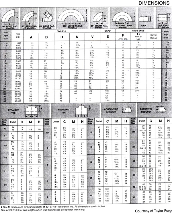


8.2 Flanges
Flanges are devices used in connecting pipes to equipment nozzles (Figures 8.3 and 8.4) and to devices such as valves. Flanged connections are an effective alternative to welded or threaded connections and provide an advantage of easy dismantling for maintenance and inspection.

Flange connecting pipe to a vessel nozzle

Reducing flange connecting pipe to vessel nozzle
Flange Ratings: Flanges are often identified by their ratings as in “150 pound flange” also represented as 150 # or 150 lb. Flange ratings are also known as “pressure ratings” and represent the maximum pressure allowed by the codes at a given temperature. Forged Steel (FS) flanges are available in the following ratings: 150 #, 300 #, 400 #, 600 #, 900 #, 1500 #, and 2500 #. A flange rating of 150 # means that it can be used up to a maximum pressure of 150 psig at a system temperature of 500°F. If the temperature increases to 750°F, the next higher rated flange (300 #) should be used. At a system temperature of 750°F, the maximum pressure allowed is 100 psig and therefore a 150 # flange will not suffice. Both the flange diameter and thickness increase with pressure ratings.
Flange dimensions are given in Appendices 4, 5, 6 and 7 for different ratings and different types of flanges.
Flange Facings:
- Flat Face (FF): The mating surfaces are flat. (Figure 8.5)
- Raised Face (RF): The mating surfaces have a raised face of 1/16” for 150 # and 300 # flanges and 1/4” for higher ratings. In the flange dimensions charts, the 1/4” raised face is nor included and must be added. However, the 1/16” dimension is included. (Figure 8.6)
- Ring Type Joint (RTJ): The mating surfaces have a groove which houses a metallic ring that provides the sealing mechanism when tightened. No gaskets are used. (Figure 8.7)

Flat Face Weld Neck Flange

Raised Face Weld Neck Flange

Ring Type Joint Weld Neck Flange
Types of Flanges:
- Weld Neck (WN)
- Slip-on (SO)
- Threaded (THRD)
- Socket Weld (SW)
- Lap Joint (LJ)
- Reducing (RED)
- Blind (BLD)
Flange Accessories:
- Bolts
- Gaskets
Abbreviations:
RFWN – Raised Face Weld Neck Flange.
Flange dimensioning problems are given in Practical Exercise 8D.


8.3 Valves
A valve is a device that controls and regulates the flow of fluids. The different functions that can be performed by a valve are:
- Turning flow on or off (flow switch)
- Increase/decrease flow rate
- Regulate pressure, temperature
- Isolate a unit
- Reverse the flow direction
Typical parts of a valve:
- Body
- Regulator or valve element
- Valve Seat
- Hand wheel
- Stem
- Valve ends (threaded, flanged, socket welded)
Types of valves (Figures 8.8 and 8.9):
- Gate Valve: Consists of a gate as the regulator. Used primarily for on/off applications, that is fully open or fully closed.
- Globe Valve: Consists of a globe as the valve element. Used in throttling (gradually increasing or decreasing the flow) applications. Flow resistance and pressure drop are substantially higher than gate valves. Flow resistance coefficients are given in Table 8.2.
- Angle Valve: Used in throttling and in changing flow direction.
- Check Valve: Used in preventing back flow or flow in the reverse direction. Usually used in conjunction with gate or globe valves. The types are “Swing Check Valve” and “Lift Check Valve”.
- Ball Valves: Uses a hollow metal ball as the regulator. Provides tight closure and simple open/close operation.
- Plug Valve: Uses a hollow, tapered wedge as the valve element. Provides a tight closure but requires constant lubrication.
- Butterfly Valve: Has a very simple valve body (a ring), which houses a wafer as the valve element. Has lower turbulence and pressure drop and is useful for larger flow rates.
- Relief Valves: Pressure Safety Valve (PSV) is used in maintaining system pressure at safe levels. PSV opens when the system pressure exceeds safety limits and closes when the system returns to normal level.
- Control Valves: Usually automated globe valves used in monitoring and regulating process variables. Control Valve Manifolds are described in Chapter 5.
Valve Operators: Devices used in opening and closing valves. There are two types of operators – manual and automatic.
- Manual Operators: Hand wheels, Levers, Gears, Chains.
- Automatic Operators: They are also known as “actuators”. Actuators use external power to open and close valves. The power sources for actuators could be hydraulic, pneumatic, or electric motors.


Types of Valves (Source: “Flow of Fluids”, Crane Technical Paper no. 410)
Note: Valve dimensions for 300 # valves are given in Appendix 8.
Friction Loss Coefficients for Fittings and Valves Source: “Chemical Engineers’ Handbook”, Perry, 5th edition, McGraw-Hill.
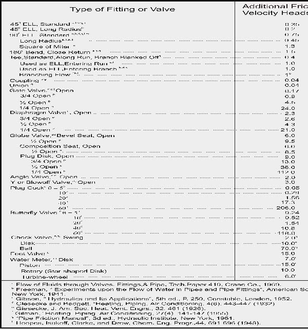

Practical exercises in Metric


8.4 Summary
The different components of a piping system viz., fittings, flanges and Valves have been described in this chapter. Different types of fittings and pipe measures have been mentioned. Flange types, ratings and facings are listed here.
This chapter includes drawings for different pipe routings.

Piping arrangement drawing- single line

“Section A-A” Elevation view

3-D model of Unit 01

Line 01-12-C30-4 (Plans, Sections and Isometric)

Model of a piping assembly mounted on a skid. (Model courtesy of Gene Eckert, ECAD, Inc.)

Skid Model, Plan View

Skid Model, Elevation view.

Piping drawing used in fabrication and construction.
This chapter provides an overview of materials commonly used in piping systems. It describes classification and specification of materials. It also describes factors used in selection of materials.
Learning objectives
- Introduction.
- Material classification systems and specifications.
- Common ASTM piping materials.
- Selection criteria for materials.
- Piping specifications (piping classes).
- Material testing and certificates.
10.1 Introduction
Selection of appropriate piping materials plays an important role in ensuring the safety and integrity of piping systems. The service conditions, namely, pressure, temperature and the nature of the fluid flowing in the pipe dictate the choice of materials. Cost is also an important factor. Evaluation of expected material behavior under given process conditions generally requires input from a material specialist. However, piping engineers and designers need to have a basic knowledge of material classifications, material specifications and material properties. Knowledge of material properties and designations is essential for performing pipe stress analysis.
10.2 Material classification system and specifications
Materials can be identified by the following methods:
- Generic descriptions
- Trade names
- Standardized alphanumeric designations
Generic descriptions: Generic descriptions group materials into broad categories based on composition and properties. Generic descriptions can range from broad descriptions to specific, detailed descriptions. Examples of generic descriptions are:
- Metals and non-metals
- Ferrous metals and non-ferrous metals
- Carbon steel (or low carbon steel)
- Low alloy steel (or Cr-Mo steel, or 2 1/4 Cr – 1 Mo Steel)
- Stainless steel (or Austenitic SS or 300 series Austenitic SS)
Trade Names: Manufactures use trade names to provide unique identification to their products. Examples of trade names are:
- Inconel 625
- Incoloy 825
- Hastelloy C-276
- Carlson Alloy 2205 Duplex SS
- Allegheny Ludlum AL 2205 Duplex SS
- UR52+ Duplex SS
Alphanumeric Description: Alphanumeric descriptions for materials originate from professional and standards organizations such as American Society for Testing of Materials (ASTM) and American Iron and Steel Institute (AISI). The overwhelming number of such descriptions has created a need for a common, widely accepted and used numbering system. The result has been the emergence of Unified Numbering System (UNS). However, the reality is that the use of prevailing designations from ASTM, AISI will continue despite the presence of UNS descriptors.
The alphanumeric designations of AISI and UNS are briefly described here.
AISI Numbering System: The AISI designation for carbon steels and low alloy steels consists of a four-digit number. The first and the second digits indicate the primary and secondary alloy classes to which the steel belongs. The third and fourth digits, xx, indicate the carbon content in 0.xx %. Examples of AISI material designations are:
- 1030: Plain carbon steel with 0.30% carbon
- 1320: Manganese Steels with 1.60-1.90% Mn and 0.20%C
- 25xx: 5% Nickel steels with 0.xx % C
- 33xx: Ni (3.25 – 3.75%), Cr (1.40 – 1.75%) Steels
- 41xx: Cr (about 1%), Mo (about 0.2%) Steels
- 51xx: Cr (about 1%) Steels
- 61xx: Cr (~1%), Vandium (~0.15%) Steels
Unified Numbering System (UNS): The Unified Numbering System avoids the confusion of multiple designations (from different organizations) for the same material by providing a unique and consistent identification number. UNS is not a specification; it does not specify requirements of quality, composition and mechanical properties. It provides the uniformity required for efficient indexing, record keeping and cross-referencing. The use of UNS is rapidly increasing and many codes such as B31.3 are beginning to use UNS designations.
The UNS designation has six alphanumeric characters – a letter prefix followed by five digits. Usually, the letter prefix indicates the family of metals (A for aluminum, S for Stainless Steels). Group examples of UNS designations are described here.
- G00001 – G99999: AISI and SAE (Society of Automotive Engineers) carbon and alloy steels
- S00001 – S99999: Heat and corrosion resistant stainless steels.
- A 00001 – A99999: Aluminum and aluminum alloys
- C00001 – C99999: Copper and copper alloys.
Specific examples of UNS designations are:
- UNS No. N04400 (Nickel alloy, equivalent ASTM designation: B165)
- UNS No. C71500 (copper alloy, equivalent ASTM designation: B467)
- UNS No. G10200 (AISI 1020 Carbon steel with 0.20% carbon)
Designations and Descriptions of Common Piping Materials: Most components of piping systems are constructed from carbon steels and alloy steels such as stainless steels. Common ASTM designations and descriptions of pipe materials are given here.
- ASTM A106 Gr.B: Carbon steel seamless pipe (most commonly used material for pipe)
- ASTM A53 Gr.B: Carbon steel seamless or Electric Resistance Welded (ERW) pipe.
- ASTM A333 Gr.6: Low and Intermediate Alloy Steel pipe
- ASTM A312 TP304: Seamless Stainless Steel pipe.
- ASTM B42: Copper alloy pipe
- ASTM B161: Nickel alloy pipe
- ASTM B210, Tempers O and H112: Aluminum alloy pipe (“O” indicates annealed material “H112” indicates strain-hardened material)
Common API (American Petroleum Institute) pipe materials are:
- API 5L, Seamless: Carbon Steel Seamless pipe
- API 5LX 46 Seamless: Carbon steel seamless pipe with specified Minimum Yield Strength of 46,000 psi (316.5 MPa)
In addition to pipe, piping systems consist of fittings (elbows, tees etc.), flanges and valves. Material designations of piping system components (other than pipe) are presented here.
Common ASTM Designations of Flanges, Pipe Fittings and valves:
- ASTM A 105: Carbon steel flanges and forged fittings
- ASTM A 182: Alloy Steel (for example, stainless steel) flanges, fittings and valves for high temperature service
- ASTM A 126: Gray Cast Iron Castings for Valves, Flanges and Pipe Fittings
- ASTM A 351: Austenitic Steel Casting for High Temperature Service
- ASTM A 350 Gr. LF 2: Carbon Steel/Low Alloy Steel forgings for piping components.
- ASTM A 182 Gr.F304: 18cr-8Ni stainless forgings for high temperature service
10.3 Piping specifications
Piping Specifications (also known as “Piping Materials Specifications” or “Piping Class”) provides detailed information on materials to be used for components of a piping system under certain conditions of temperature, pressure and fluid being serviced. An example of Piping Specification is shown in Figure 6.2. Piping specifications also contains information on required wall thickness, corrosion allowance, and Post Weld Heat Treatment (PWHT) and Radiographic Examinations. Piping Specifications are designated by alphanumeric representation such as A1, A2. These designations form part of the “Piping Line Number” on Piping and Instrumentation Diagrams (P&IDs), Piping Isometrics and other documents. A typical piping line number is 10” – PG – 0008 – A1. 10” is the Nominal Pipe Size (NPS), PG is the service designation, which, in this case, is Process Gas, 0008 is the line sequence number and A1 is the piping specification.
10.4 Material selection
The selection of appropriate material for a given application involves the consideration of the following aspects:
Process Requirements: Process requirements include pressure, temperature and the corrosion characteristics of the fluid being handled. Corrosion characteristics of the fluid being serviced play a major role. Carbon Steel piping should be adequate for non-corrosive substances as long as the temperature is not very high (less than 300°C or 572°F). For corrosive substances at normal temperature a lined pipe can provide satisfactory service. Stainless steel pipe is the preferred choice for corrosive substances and also for high temperature service. For pipes handling corrosive fluids, adequate corrosion allowance must be indicated in the piping specifications. It is very important to note that codes usually do no provide guidelines on how to select materials for specific service conditions. For example, the following statements are found in ASME B31.3 concerning material selection: “Compatibility of materials with the service and hazards from instability of contained fluids are not within the scope of this code”. “Selection of materials to resist deterioration in service in not within the scope of this code”.
Mechanical Design: Mechanical design involves ensuring the mechanical integrity and safety of piping systems and pressure vessels. Mechanical design considers the following parameters:
- Allowable Stress (of the selected material at design temperature)
- Design Pressure
- Corrosion Allowance
- Requirements for Weld Procedure Qualification
- Forming and Bending Practices
- Post-Weld Procedures and Examinations
The codes usually have guidelines and formulas related to mechanical design since codes are primarily concerned with mechanical integrity and safety aspects. Some of the important aspects of mechanical design are the calculation of minimum required wall thickness for pressure piping and specifying appropriate class of flanges. The “Piping Specifications” or “Piping Class” discussed earlier is an outcome of mechanical design.
Economics and Availability: Cost is a very important factor in material selection. Different material options must be evaluated on the basis of “life-cycle” costs. For example, it may be cheaper to replace corroded tubes in a heat exchanger as compared to specifying a very expensive tube material. Procurement of expensive, high alloy steels may be difficult and can cause delays in the project. Sometimes, materials may not be available exactly in the form required which can force the specification to be revised.
10.5 Quality control and material certification
The materials being procured for a project have to meet the engineering and design requirements. Material vendors usually provide this confirmation through documents such as:
- Test Certificates
- Material Test Reports (MTRs)
- Certificates of Compliance
The materials procurement department should have quality checks in place to assure the quality of incoming material. Quality Assurance (QA) activities can range from visual inspection, verifying data stamped on commodities to random testing in detail.
Pipe Data and Fitting Dimensions
LINEAR CONVERSION
Inches to Millimeters
(1 inch = 25.4 millimeters)


Source: “Piping Guide: Second Edition”, Sherwood, David R Whistance, Dennis J, Syentek Book Co. 1991.


Source: “Pipe Drafting and Design”. Parisher, Roy A and Rhea, Robert H, gulf Publishing, 2002.


Professional Certificate of Competency in Advanced TCP/IP-Based Industrial Networking
Designed for engineers and technicians who need practical knowledge in…Read more
Professional Certificate of Competency in Allen Bradley Controllogix / Logix5000 PLC Platforms
Designed for engineers and technicians who need practical knowledge in…Read more
Professional Certificate of Competency in Arc Flash Protection
Designed for engineers and technicians who work in the electrical…Read more
Professional Certificate of Competency in Chemical Engineering and Plant Design
Designed for engineers and technicians who need practical knowledge in…Read more
Professional Certificate of Competency in Circuit Breakers, Switchgear and Power Transformers
Designed for engineers and technicians who need practical knowledge regarding…Read more
Professional Certificate of Competency in Control Valve Sizing, Selection and Maintenance
Designed for engineers and technicians who need a solid understanding…Read more
Professional Certificate of Competency in Electrical Power System Fundamentals for Non Electrical Engineers
Designed for engineers and technicians who need to understand the…Read more
Professional Certificate of Competency in Electrical Power System Protection
Designed for engineers and technicians who need practical skills and…Read more")
Professional Certificate of Competency in Electrical Wiring Standards: AS/NZS 3000:2018 (Australia and New Zealand Only)
This professional development course is designed for engineers and technicians…Read more
Professional Certificate of Competency in Fundamental E & I Engineering for Oil and Gas Facilities
Designed for engineers and technicians who need to update their…Read more
Professional Certificate of Competency in Gas Turbine Engineering
Designed for engineers and technicians who need practical skills in…Read more
Professional Certificate of Competency in Hazardous Areas and Intrinsic Safety For Engineers and Technicians
Designed for engineers and technicians who need to understand the…Read more")
Professional Certificate of Competency in Heating, Ventilation and Air-Conditioning (HVAC)
Designed for engineers and technicians from a wide range of…Read more
Professional Certificate of Competency in IEC 61850 Based Substation Automation
Designed for engineers and technicians who need to understand the…Read more
Professional Certificate of Competency in Industrial Data Communications
Designed for engineers and technicians who need to understand how…Read more
Professional Certificate of Competency in Instrumentation, Automation and Process Control
Designed for engineers and technicians who need to gain practical…Read more
Professional Certificate of Competency in Machine Learning and Artificial Intelligence
This professional development course is designed for engineers and technicians…Read more
Professional Certificate of Competency in Mechanical Engineering
This professional development course is designed for engineers and technicians…Read more
Professional Certificate of Competency in Onshore and Offshore Pipeline Systems
Designed for engineers and technicians who need to gain an…Read more
Professional Certificate of Competency in Power Distribution
designed for engineers and technicians who need to gain a…Read more
Professional Certificate of Competency in Practical Machine Learning Using Python for Engineers and Technicians
Designed to use Python Programming to work with machine learning…Read more
Professional Certificate of Competency in Practical Python for Engineers and Technicians
Designed for engineers and technicians who need to understand the…Read more & SCADA Systems")
Professional Certificate of Competency in Programmable Logic Controllers (PLCs) & SCADA Systems
Designed for engineers and technicians who need to get practical…Read more
Professional Certificate of Competency in Project Management for Engineers & Technicians
This professional development course is designed for engineers and technicians…Read more
Professional Certificate of Competency in Safety Instrumentation Systems for Process Industries
Professional development course designed for engineers and technicians who want…Read more
Professional Certificate of Competency in Sewage and Effluent Treatment Technologies
Designed for engineers and technicians who need practical skills and…Read more
Professional Certificate of Competency in Structural Design for Non Structural Engineers
Professional development course designed for engineers and technicians who need…Read more")
Professional Certificate of Competency in Substation Design (Main Equipment)
Professional development course is designed for engineers and technicians who…Read more")
Professional Certificate of Competency in Substation Design (Control, Protection and Facility Planning)
Designed for engineers and technicians who need to gain practical…Read more
Professional Certificate of Competency in the Fundamentals of Process Plant Layout & Piping Design
Professional development course is designed for engineers and technicians who…Read more
Professional Certificate of Competency in Practical Mechanical Sealing
This professional development course is designed for engineers and technicians…Read more
Professional Certificate of Competency in Road Construction
This professional development course is designed for engineers and technicians…Read more
Professional Certificate of Competency in Specification and Technical Writing
Master the art of writing clear, accurate, and professional technical…Read more
Professional Certificate of Competency in Hydraulics and Pneumatics
Overview of all aspects related to the construction, design, operation,…Read more
Professional Certificate of Competency in Big Data and Analytics in Electricity Grids
This course explores the use of big data & data…Read more
Professional Certificate of Competency in Renewable Energy Systems
This course covers various renewable energy systems that are popular…Read more
Professional Certificate of Competency in Smart Grids
A smart grid is an electricity network that uses digital…Read more
Professional Certificate of Competency in Hydrogen Energy – Production, Delivery, Storage and Use
Hydrogen energy short course designed for engineers and professionals interested…Read more")
Professional Certificate of Competency in Building Information Modelling (BIM)
This professional development course is covering practical aspects of using…Read more
Professional Certificate of Competency in Industrial Internet of Things
Internet of Things (IoT) is the most sort after technology…Read more