")
52896WA Advanced Diploma of Civil and Structural Engineering (Materials Testing)
Investigation of the properties of construction materials, the principles which…Read more")
Graduate Diploma of Engineering (Safety, Risk and Reliability)
The Graduate Diploma of Engineering (Safety, Risk and Reliability) program…Read more
Professional Certificate of Competency in Fundamentals of Electric Vehicles
Learn the fundamentals of building an electric vehicle, the components…Read more
Professional Certificate of Competency in 5G Technology and Services Overview
Learn 5G network applications and uses, network overview and new…Read more
Professional Certificate of Competency in Clean Fuel Technology - Ultra Low Sulphur Fuels
Learn the fundamentals of Clean Fuel Technology - Ultra Low…Read more
Professional Certificate of Competency in Battery Energy Storage and Applications
Through a scientific and practical approach, the Battery Energy Storage…Read more
52910WA Graduate Certificate in Hydrogen Engineering and Management
Hydrogen has become a significant player in energy production and…Read more
Professional Certificate of Competency in Hydrogen Powered Vehicles
This course is designed for engineers and professionals who are…Read more
If you are a non-chemical engineer this manual will provide you with the fundamentals in this area and enable you to confidently talk to and work effectively with chemical engineers and process equipment.
Revision 8
Vivek Mehra, BSc, MBA
Website: www.idc-online.com
E-mail: idc@idc-online.com
IDC Technologies Pty Ltd
PO Box 1093, West Perth, Western Australia 6872
Offices in Australia, New Zealand, Singapore, United Kingdom, Ireland, Malaysia, Poland, United States of America, Canada, South Africa and India
Copyright © IDC Technologies 2011. All rights reserved.
First published 2005
All rights to this publication, associated software and workshop are reserved. No part of this publication may be reproduced, stored in a retrieval system or transmitted in any form or by any means electronic, mechanical, photocopying, recording or otherwise without the prior written permission of the publisher. All enquiries should be made to the publisher at the address above.
Disclaimer
Whilst all reasonable care has been taken to ensure that the descriptions, opinions, programs, listings, software and diagrams are accurate and workable, IDC Technologies do not accept any legal responsibility or liability to any person, organization or other entity for any direct loss, consequential loss or damage, however caused, that may be suffered as a result of the use of this publication or the associated workshop and software.
In case of any uncertainty, we recommend that you contact IDC Technologies for clarification or assistance.
Trademarks
All logos and trademarks belong to, and are copyrighted to, their companies respectively.
Acknowledgements
IDC Technologies expresses its sincere thanks to all those engineers and technicians on our training workshops who freely made available their expertise in preparing this manual.
Table of Contents
1 Chemical engineering- an overview 1
1.1 Basics of chemical engineering 1
1.2 Unit operations 2
1.3 Thermodynamics 8
1.4 Chemical Kinetics 9
1.5 Chemical engineer – scope & responsibilities 9
1.6 “Ten greatest achievements” of chemical engineering 15
1.7 Chemical engineering “Today & Tomorrow” 17
2 Stoichiometry 19
2.1 Introduction 19
2.2 Understanding chemical formulas and equations 19
2.3 Balancing chemical equations 25
2.4 Chemical periodicity 27
2.5 Molecular weight 28
2.6 The mole and molar mass 29
2.7 Percent composition 29
2.8 Introduction to solutions 32
2.9 Units and dimensions 33
2.10 Process variables 36
3 Chemical kinetics 41
3.1 Chemical reactions – Basic concepts 41
3.2 Classification of chemical reactions 42
3.3 Chemical reaction profile 43
3.4 Classification of reactors 44
3.5 Catalysts 49
3.6 Promoters 53
3.7 Efficiency criteria of a chemical process 55
4 Fluid mechanics 57
4.1 Introduction 57
4.2 Volumetric properties of liquids 57
4.3 Liquid-column manometers 58
4.4 Mechanical pressure gauges 61
4.5 Measurement of fluid flow 65
4.6 Valves 82
4.7 Fluid moving machinery 90
4.8 Centrifugal pumps 91
4.9 Positive-displacement pumps 92
4.10 Agitation equipments 96
5 Heat transfer and its applications 101
5.1 Heat transfer mechanism 101
5.2 Heat exchangers 101
5.3 Boilers 111
5.4 Evaporators 115
6 Mass transfer and its applications 125
6.1 Mass transfer phenomena 125
6.2 Distillation 125
6.3 Types of distillation columns 127
6.4 Column internals 128
6.5 The types of distillation 137
6.6 Sublimation 143
6.7 Leaching 143
6.8 Centrifugal extractors 148
6.9 Gas absorption 149
6.10 Cooling towers 152
6.11 Desiccant dehumidifiers 157
6.12 Adsorptions systems 159
6.13 Drying 163
6.14 Drying equipment 164
7 Thermodynamics 183
7.1 Applications of thermodynamics principles 183
7.2 Compressor 187
7.3 Ejector-system 194
7.4 Heat conversion & power cycles 195
7.5 Refrigeration and liquefaction 211
8 Process design 217
8.1 Introduction 217
8.2 Process design considerations 218
8.3 Equipment design factors 218
8.4 A look at common industrial chemicals 219
8.5 Materials of construction 221
8.6 Types of corrosion 222
8.7 Linings for chemical plants and equipment 223
8.8 Rules of thumb 224
9 Process control 231
9.1 Overview 231
9.2 Control system 231
9.3 Practical control examples 234
9.4 Control actions 240
9.5 Examples of control 241
9.6 Control loop diagrams 248
9.7 Modes of automatic control 249
10 Chemical process safety 259
10.1 Safety responsibilities 259
10.2 Standard safety rules and regulations 261
10.3 Chemical hazards and chemical safety data sheets 262
10.4 General safety practices 266
10.5 Good housekeeping plan 276
10.6 Personal protective equipments 276
11 Classification of process diagrams/data sheets and their application 277
11.1 Introduction 277
11.2 Types of process drawings 277
11.3 Block Flow Diagram (BFD) 277
11.4 Process Flow Diagram (PFD) 278
11.5 Piping and Instrument Diagram (P&ID) 279
11.6 Utility Flow Diagram (UFD) 280
11.7 Data sheets 280
12 Unit operations of particulate solids 283
12.1 Storage of solids 282
12.2 Feeders 286
12.3 Crushers and mills 288
12.4 Cutting machines 295
12.5 Crystallization 296
12.6 Mixers 298
12.7 Mechanical separation 301
12.8 Powder compacting equipments 306
12.9 Filtration 310
12.10 Cryogenic grinding 314
12.11 Blending 315
13 Process economics 317
13.1 Capital investment 317
13.2 Total product costs 319
13.3 Economic analysis 320
13.4 Life cycle analysis 321
13.5 Real-Time Optimization (RTO) of chemical processes 322
Appendix A Periodic Table 325
Appendix B Fundamental physical constants 327
Appendix C Process equipment symbols 331
Appendix D Typical instrumentation representation 349
Appendix E Typical P&ID 375
Appendix F Typical process data sheet 377
Appendix G Some websites for safety information 379
Appendix H Practical exercises 383
1.1 Basics of chemical engineering
Chemical engineering is associated with:
- Efficient and economic control of chemical processes
- Design of chemical reactors and process plants
- Development of sustainable products
- Pollution control and treatment of industrial wastes

Man has utilized chemicals for a long time but chemical engineering was recognized as a separate field only a century ago. Egyptians developed certain types of papers as early as 2000 BC and glass is presumed to have been invented close to 5000 BC. Perhaps the single most important pursuit in chemistry was the ‘manufacture’ of gold. As soon as man discovered this metal he became obsessed with it. No civilization could resist the shine of this precious metal. In the middle ages a set of ‘mad-hatters’ decided to live their dream of converting base metals to gold. The conversion became the ‘Holy Grail’ of those pursuing it. Some of the greatest discoveries in physical chemistry were made by these people even though the ‘Grail’ still remains elusive. Today their work is recognized as a pioneering effort and the first standardization of manufacturing techniques which ultimately gave us the field of Chemical Engineering. These scientists are collectively referred to as the Alchemists.
But like all other engineering disciplines, chemical engineering ultimately got recognized as a major field of engineering in the 19th century. During this period of industrial revolution the requirement for engineers who could design chemical reactors and plants was greatly enhanced because of the increase in the use of chemicals in every day life. This was a time when the chemical industry grew rapidly and it needed experts to handle chemical plants and their design. Up till 1910, the chemical industry had to rely mainly on mechanical engineers and chemists.

Typical chemical process plant
However, due to emerging methods and techniques, chemical processing was becoming too complex, and it called for the training of engineers in the field of chemical processing. The design of chemical reactors and other equipment involved in a chemical process plant was beyond the scope for chemists and mechanical engineers. Keeping all these factors in view, the start of a new engineering discipline for chemicals was seriously considered.
As a result, chemical engineering emerged as a separate discipline in 1910 when professors at Massachusetts Institute of Technology (MIT) realized that neither mechanical engineering nor chemistry offered sound approaches to a chemical plant’s design. So a new branch of engineering was started to prepare engineers specializing in the design, operation, and construction of chemical processing plants. Subsequently, this field got universal recognition and many institutions throughout the globe started teaching this subject. Today, thousands of chemical engineers are working around the globe and scores of young men and women are being trained.
1.2 Unit operations
Processing and manufacturing of chemicals in industries is based on many operations such as heat transfer, mass transfer, fluid flow, distillation, evaporation, absorption, drying, leaching, mixing, crystallization, adsorption, and humidification.
The idea of treating these processes of the chemical industry as unit operations was also put forward by the professors of the MIT. They characterized the physical operations necessary for manufacturing chemicals as unit operations. Although originally largely descriptive, these unit operations have been the object of vigorous study and now can be used with sound mathematical procedures for plant design predictions.
During 1930, P. H. Groggins proposed a similar approach to classifying chemical operations as unit processes. Such processes include nitration, oxidation, hydrogenation, sulphonation, chlorination, and esterification. Development of a lab-scale process, designed by a chemist, into a large-scale industrial process is a difficult task and requires the knowledge of the chemicals as well as the mechanical aspects of the equipment required.
The physical operations necessary for manufacturing chemicals are called unit operations. It is a method of organizing much of the subject matter of chemical engineering. Unit operations can be, no doubt, called the heart of chemical engineering. The unit operations concept is based on the fact that by systematically studying the operations (such as heat transfer, mass transfer, fluid flow, drying, distillation, evaporation, absorption, extraction, and mixing) involved in the chemical industry, the treatment of all processes is unified and simplified. The unit operations are largely used to conduct the primary physical steps of preparing the reactants, separating and purifying the products, recycling unconverted reactants, and controlling the energy transfer into or out of the chemical reactors. The design of the equipment involved for these operations is also studied in unit operations. Because of the complexity and variety of the modern chemical manufacturing processes the need for arranging the different processes systematically has become undeniable. The chemical steps themselves are conducted by controlling the flow of material and energy to and from the reaction zone.
1.2.1 Fluid mechanics
The branch of engineering that investigates the behavior of fluids is called fluid mechanics. It is a part of a larger branch of engineering called continuum mechanics, which deals with the behavior of fluids as well as stressed solids. A fluid is a substance that does not permanently resist distortion. An attempt to alter the shape of a mass of fluid results in layers of fluids sliding over one another until a new shape is attained. During the change in shape, shear stresses exist depending upon the viscosity of the fluid and the rate of sliding, but when the final shape is achieved all the shear stresses disappear. A fluid in equilibrium is free from shear stresses.
Fluids may be compressible or incompressible. If the density of a fluid changes slightly with the changes in temperature and pressure then such a fluid is called incompressible and if the density changes significantly then such a fluid is said to be compressible. Gases are generally considered to be compressible while liquids are considered incompressible.
The behavior of fluids is very important in chemical engineering. It is a major part of unit operations principle. Understanding of fluids is essential not only for accurately treating problems in the movement of fluids through pipes, compressors, pumps, and all kinds of process equipment but also for the study of heat flow and many separation principles that depend on diffusion and mass transfer. Design and study of measuring devices (such as flow meters, area meters, pressure gauges), transportation equipment (such as compressors and pumps), and mixing and agitation equipment (such as mixers and agitators) are considered in fluid mechanics.
Fluid mechanics can be divided into two branches:
- Fluid statics
- Fluid dynamics
Fluid statics deals with the fluids at rest or in equilibrium state with no shear stress. It is concerned with the properties and behavior of fluids. In the case of liquids this subject is called hydrostatics and in the case of gases it is called pneumatics.
Fluid dynamics, also called fluid flow, deals with the flowing fluids or with fluids when section of the fluid is in motion relative to the other parts. The flow of a fluid is of two types:
- Laminar flow: The flow in which the layers of the fluid are flowing parallel to the axis of the pipe or conduit
- Turbulent flow: The flow in which the layers of the moving fluids are not parallel to the axis of the pipe and the fluid is disturbed from point to point
Chemical engineers are continuously involved with the flow of fluids. In industrial applications, they have to transport fluids from one point to another through pipes or open ducts which require the determination of pressure drops in the system, selection of a proper type of pump or compressor, power required for pumping or compression, and measurement of flow rates. All these aspects are studied in fluid flow. A major portion of fluid flow deals with the transportation, metering, and mixing & agitation of fluids.
1.2.2 Heat transfer
Heat transfer is the branch of engineering that deals with the rates of heat exchange between hot and cold bodies. The driving force for heat transfer is the temperature difference per unit area or temperature gradient. In a majority of chemical processes heat is either given out or absorbed. Most of the times the fluids must be heated or cooled in a variety of equipment such as boilers, heaters, condensers, furnaces, dryers, evaporators, and reactors. In all of these cases the fundamental problem encountered is the transferring of heat at the desired rate. Some times it is necessary to prevent the loss of heat from vessels or pipes.
The control of flow of heat at the desired rate is one of the most important areas of chemical engineering. The principles and laws governing the rates of heat flow are studied under the heading of heat transfer. Even though the transfer of heat is involved in every unit operation, in evaporation, drying, and combustion the primary concern is the transfer of heat rather than the transfer of mass and these operations are governed by the rate of heat transfer. Laws and equations of heat transfer are used for the designing of the equipment required for these processes.
Evaporation is the process used to concentrate a solution consisting of a non-volatile solute and volatile solvent. In a majority of evaporations the solvent is water.
Drying is the removal of relatively small amounts of water or other liquid from the solid material to reduce the content of residual liquid to a low value.
Heat transfer can take place through the following three modes of (heat) transfer:
- Conduction
- Convection
- Radiation
However, most of the processes are a combination of two or more modes of heat transfer.
Conduction
Conduction is the transfer of heat through fixed material such as stationary walls. In a solid, the flow of heat is the result of the transfer of vibrational energy from one molecule to another, and in fluids it occurs in addition as a result of the transfer of kinetic energy. Heat transfer through conduction may also arise from the movement of free electrons.
Convection
Convection is the heat transfer occurring due to the mixing of relatively hot and cold portions of a fluid. If this mixing takes place due to density differences, then such a process is called natural or free convection, e.g. a pool of liquid heated from below. However, if the mixing takes place due to eddies produced by mechanical agitation then such a process is called forced convection. It is important to note that convection requires mixing of fluid elements and is not governed by just the temperature difference as in conduction and radiation.
Radiation
Radiation is the transfer of radiant energy from one body to another. All materials radiate thermal energy in the form of electromagnetic waves. When radiation falls on a second body it may be partially reflected, transmitted, or absorbed. It is only the fraction that is absorbed that appears as heat in the body. While heat transfer deals with the transfer of heat between hot and cold bodies independently, Process heat transfer deals with the rates of heat exchange as they occur in the heat-transfer equipment of the engineering and chemical processes.
1.2.3 Mass transfer
Mass transfer is involved with the transfer of a component in a mixture from a region in which it has a high concentration to a region in which its concentration is lower. This process can occur in a gas, liquid, or vapor. It can result from the random velocities of the molecules (molecular diffusion) or from the circulating or eddy currents present in a turbulent fluid (eddy diffusion). Like temperature gradient is the driving force for heat transfer, the driving force for mass transfer is the concentration gradient. Many unit operations such as distillation, absorption, extraction, leaching, membrane separation, dehumidification, crystallization, ion exchange, and adsorption are considered as mass transfer operations. Even though transfer of heat is also involved in these operations but the rate of mass transfer governs the rate phenomena in these processes. Unlike purely mechanical separation processes, which utilize density difference and particle size, these methods make use of differences in vapor pressure, solubility, or diffusivity.
Distillation
The function is to separate, by vaporization, a liquid mixture of miscible and volatile substances into individual components or, in some cases into groups of components.
Absorption
In absorption a soluble vapor is absorbed by means of a liquid in which the solute gas is more or less soluble, from its mixture with an inert gas. The solute is subsequently recovered from the liquid by distillation, and the absorbing liquid can either be discarded or reused.
Desorption
When a solute is transferred from the solvent liquid to the gas phase, the operation is known as stripping or desorption.
Dehumidification
A pure liquid is partially removed from an inert or carrier gas by condensation. Usually the carrier gas is virtually insoluble in the liquid.
Membrane separations
In membrane separations, including gas separations, reverse osmosis, and ultra filtration, one component of a liquid or gaseous mixture passes through a selective membrane more readily than the other components.
Adsorption
In adsorption a solute is removed from either a liquid or a gas through contact with a solid adsorbent, the surface of which has a special affinity for the solute.
Liquid extraction
Also called solvent extraction, a mixture of two components is treated by a solvent that preferentially dissolves one or more of the components in the mixture. The mixture so treated is called the raffinate and the solvent-rich phase is called extract. In extraction of solids, or leaching, soluble material is dissolved from its mixture from an inert solid by means of a liquid solvent.
Crystallization
This process is used to obtain materials in attractive and uniform crystals of good purity, separating a solute from a melt or a solution and leaving impurities behind.
1.2.4 Solid particulate operations
Also termed as particle technology, this branch of unit operations deals with solid handling and is mainly concerned with the mixing, size reduction, and mechanical separation of solids. Solids in general are more difficult to handle than fluids. In processing solids appear in a variety of forms such as angular pieces, continuous sheets, finely divided powders. They may be hard and abrasive, tough and rubbery, soft or fragile, dusty, cohesive, free flowing, or sticky. Whatever their form, means must be found to handle these solids.
Mixing of solids resembles to some extent with the mixing of low-viscosity liquids, however, mixing of solids requires much more power. In mixing two or more separate components are intermingled to obtain a uniform product. Some of the mixers and blenders used for liquids are also used for solids. Solid mixers mainly used are kneaders, dispersers, masticators, mixer-extruders, mixing rolls, pug mills, ribbon blenders, screw mixers, tumbling mixers, and impact wheel.
Size reduction
Size reduction, referred to as communition, is a term applied to the methods and ways used to cut or breakdown solid particles in smaller pieces.
Reduction of particle size is usually carried in four ways:
- Compression
- Impact
- Attrition or rubbing
- Cutting
Separations
Separations can be classified into two classes:
- Diffusional operationsInvolves the transfer of material between phases e.g. absorption, distillation, adsorption etc
- Mechanical separationsIt is used for heterogeneous mixtures. This class of separation processes consists of techniques based on physical differences between the particles such as size, shape, or density. They are applicable to separating solids from gases, liquid drops from gases, solids from solids, and solids from liquids
Two general methods are:
- The use of a sieve, or membrane such as a screen or a filter, which retains one component and allows the other to pass
- The utilization of differences in the rate of sedimentation of particles or drops as they move through a liquid or a gas. The operations included in mechanical separations are screening, filtration, and gravity and centrifugal settling
Screening
Screening is a method of separating particles according to size alone. In industrial screening the solids are dropped or thrown against a screening surface. The undersize (also called fines) pass through the screen openings leaving behind oversize (also called tails) particles. Industrial screens are made from woven wire, silk, plastic cloth, metal, and perforated or slotted metal plates. Stationary screens, grizzlies, gyrating screens, vibrating screens, and centrifugal sifters are used for this purpose.
Filtration
Filtration is the separation of solid particles from a fluid by passing the fluid through a filtering medium through which the solids are deposited. Industrial filtrations range from simple straining to highly complex separations. The fluid may be a liquid or a gas; the valuable stream from the filter may be fluid, solid, or both.
Filters are divided into three main groups:
- Cake filters separate relatively large amounts of solids as a cake of crystals or sludge. Filter press, shell and leaf filter, belt filter, rotary drum filter, batch centrifuge filters are used for this purpose
- Clarifying filters remove small amounts of solids to produce a clean gas or a sparkling clear liquid by trapping the solid particles inside the filter medium. Gravity bed filters, cartridge filters, edge filters, tank filters, pad filters, bag filters, and granular bed filters are used for this purpose
- Cross-flow filters are used for very fine particles or for micro-filtration. In a cross-flow filter the feed suspension flows under pressure at a fairly high velocity across the filter medium. Some of the liquid passes through the medium as a clear filtrate, leaving behind a more concentrated suspension. For these filters different types of membranes are used
Settling processes
Settling processes are used for mechanical separations, utilizing the movement of solid particles or liquid drops through a fluid.
Gravity settling processes are based on the fact that particles heavier than the suspended fluid can be removed from a gas or liquid in a large settling tank in which the fluid velocity is low and the particles are allowed a sufficient time to settle out.
Gravity settling process is of two types:
- Clarifier: A settler that removes virtually all the particles from a liquid
- Classifier: A device that separates the solid into two fractions
Centrifugal settling processes are efficient than gravity settling processes. A given particle in a given fluid settles under gravitational force at a fixed maximum rate. To increase the settling rate the force of gravity acting on the particle may be replaced by a much stronger centrifugal force. Centrifugal separators, to certain extent, have replaced the gravity separators because of their greater effectiveness with fine drops and particles and their much smaller size for a given capacity. The most widely used type of centrifugal separators is the cyclone separator. Other types mostly used are centrifugal decanters, tubular centrifuges, disk centrifuge, nozzle discharge centrifuge, and centrifugal classifiers.
1.3 Thermodynamics
The transformation of heat energy into some other form of energy or the transformation of some other form of energy into heat energy is called thermodynamics. Thermodynamics is a very useful branch of engineering science and is very helpful in the treatment of such processes as refrigeration, flashing, and the development of boilers and steam and gas turbines. Thermodynamics is governed by two rules called the first and second law of thermodynamics.
First law of thermodynamics
First law of thermodynamics states that Energy can neither be created nor destroyed, however it can be transferred from one form to another. This law is also known as law of conservation of energy. In thermodynamic sense, heat and work refer to energy in transit across the boundary between the system and surroundings. These forms of energy can never be stored. Energy is stored in its potential, kinetic, and internal forms. These forms reside with material objects and exist because of position, configuration, and motion of matter.
Second law of thermodynamics
The second law of thermodynamics states that it is impossible to transfer heat from a cold body to a hot body unless external work is done on the system. Or, no heat engine operating continuously in a cycle can extract heat from a hot reservoir and convert it into useful work without having a sink. The universal applicability of this science is shown by the fact that physicists, chemists, and engineers employ it. In each case the basic principles are the same but the applications differ.
Thermodynamics enables a chemical engineer to cope with a wide variety of problems. Among the most important of these are the determinations of heat and work requirements for many physical and chemical processes, and the determination of equilibrium conditions for chemical reactions and for the transfer of chemical species between phases.
1.4 Chemical kinetics
This branch is a very important activity in chemical engineering. It is primarily concerned with the exploitation of chemical reactions on a commercial scale. Its goal is the successful design and operation of chemical reactors. This activity, probably more than any other, sets chemical engineering apart as a distinct branch of engineering profession.
Design of equipment for the physical treatment steps is studied in the unit operations. The chemical treatment step of a process is studied in chemical reaction engineering. The treatment stages are the heart of a process and the core factor that makes or breaks the process economically. Reactor design uses information, knowledge, and experience from a variety of areas such as thermodynamics, chemical kinetics, fluid mechanics, heat transfer, mass transfer, and economics.
1.5 Chemical engineer – scope & responsibilities
Chemical engineers are employed in many process industries representing a diverse range of products, employers, and services. The chemical engineering profession includes a wide variety of activities in a number of institutions including industry, research, government, and academia. Chemical engineering mainly deals with industrial processes in which raw materials are changed into useful products. The chemical engineers develop, design, and engineer both complete processes and the equipment used; choose the proper raw material; operate the plants efficiently, safely, and economically; and see to it that the products meet the requirements set by the customers.
Chemical engineering is both an art and a science. Chemical engineers work in numerous areas besides petroleum refining and the petrochemical industries because their background and experience are easily portable and found useful. Products of concern to chemical engineers range from commodity chemicals like sulphuric acid and chlorine to high-tech items like lithographic support for electronic industry (Silicon chips, microprocessors) and genetically modified biochemical agents. The number of chemical engineers working throughout the world is enormous. These engineers are employed by both private and public enterprises. They work in a variety of fields besides process and designing. The wide spectrum of application of chemical engineers shows that chemical engineers must be trained to function in any phase of chemical manufacturing. A chemical engineer during his career performs various activities. From plant design to successful plant operation he has to face many tasks and challenges. To have a better understanding of the work of a chemical engineer let us consider the important activities undertaken by him
1.5.1 Process selection
The selection of a process is one of the most important and time-consuming activities undertaken by a chemical engineer. One process may be energy efficient than the other but the other may be less polluting or may have its raw materials readily available. Selecting a process out from the available options is no easy job because each process has certain advantages and disadvantages. To select a process many constraints have to be faced such as time, available data, investment, and economics. As all industries are mainly concerned with profits, out of all the constraints economics always remains the chief factor in selecting a process.
Selecting a process to be in batches or to be continuous is another critical task. Early chemical processing was normally done in batches and much continues to be done in that way. Batches can be measured correctly and are much suitable for small-scale production. However, the temperature and pressure control can be troublesome.
Furthermore time and resources lost in attaining the required conditions such as temperature and pressure, limits the use of batch processes. On the other hand, continuous processes require far smaller and less expensive equipment, have much less material in process, have less chance to ruin large quantities, have more uniform operating conditions, and give more uniform products than batch processes.
Continuous processes are very suitable for large-scale productions. However, these require concise control of flow-rates and conditions, which is impossible without high quality instrumentation. The reduction in plant cost per unit of production is often the major force in selecting a process to continuous or in batches.
1.5.2 Operation
Operation of a process plant is another important activity carried out by a chemical engineer. Chemical processing of a raw material into the desired product can only be achieved by operating the chemical plant. The quality and quantity of the product is directly dependent on the efficient operation of a plant. The smooth operation of a plant is a very difficult task and requires close attention of the engineer at all times. Many problems like temperature and pressure control, maintenance, and safety continue to arise during the plant operation. Experience and application of engineering principles is always needed to shoot out these problems. Negligence of a small problem can often lead to bigger, more complex problems and can cause unnecessary halts in production.
In order to be able to handle plant operation smoothly, a chemical engineer should start early to become familiar with the industrial equipment such as pumps, compressors, distillation columns, filter presses, and heat exchangers, etc. Almost every industry wants its engineers to be intimately familiar with every pipe & gauge of that industry. That is why every industry makes its new engineers spend their earlier time in tracing pipelines, an activity known as line tracing. The reason behind this practice is to intimately familiarize the engineers with all the pipelines, gauges, valves, and equipment of that industry so that whenever there is any fault in any section he should be able to identify the location and to work out its solution immediately.
In fact, troubleshooting is the core of plant operation. Successful plant operation of a chemical plant does not only depend upon the original strength of the materials of construction but also upon the affects of corrosion. Constant check-ups and inspection must be maintained to avoid corrosion. Mechanical failures are seldom experienced unless there has been previous corrosion or weakening by chemical attack.
Chemical manufacturing process can be divided into the following steps:
- Raw material
- Physical treatment steps
- Chemical treatment steps
- Recycle
- Product
1.5.3 Instrumentation and control
In commercial scale continuous operations the function of the workers and the supervising chemical engineer is to maintain the plant in proper running conditions. Maintaining required temperature, pressure, flow-rates, and other conditions is a very difficult task. Quality instrumentation is a must for maintaining these conditions. Instruments are the essential tools for modern processing. A chemical engineer must have the proper knowledge of the instruments involved for controlling and measuring process variables. Adequate ability to design control systems for processes and workout problems faced in controlling process operations is also essential.
Batch operation requires few instruments and hence more supervision on the part of the workers and the chemical engineer because the conditions and procedures differ from the start to the finish. Programmed instruments can solve even these problems if the expense can be justified. Instrument costs, once a trivial part of the total plant investment, have risen up to 25% of the total investment.
The use of computers has reduced this cost to some extent. Earlier plants used mechanical control instruments. These were replaced by pneumatic control systems, which were replaced by electronic control systems. Currently, plant-control is being done by DCS (Distributed Control System) using computers. DCS incorporates the use of electronic control devices but it utilizes computers to monitor and control process conditions. Even though many industries continue to use pneumatic and electronic control systems, however, the global trend is towards DCS because of its ability to handle plant operation more smoothly. Instrumentation has been forced into this position of eminence by the increase in continuous processes, increase in labour and supervision costs, the relative unreliability of human actions, and by the availability of many types of instruments at decreasing price and increasing reliability.
Instrument types include indicating instruments, recording instruments, and controlling instruments. Two types of instruments are generally used: analog and digital. Analog instruments such as pressure spring thermometer and Bourdon pressure gauges show results by mechanical movement of some type of device (e.g. spring or Bourdon tube), which is proportional to the quantity being measured. Digital devices generally utilize a transducer, a device that converts the measured signal into some other type of signal usually electronic or pneumatic. These devices also use electronic circuits, which convert the signal to readable numerical figures (digits), which are then displayed and may be recorded.
1.5.4 Chemical process economics
Economics is a vital part of an engineers work. Engineers are distinguished from scientists by their consciousness of costs and profits. Economics plays a vital role in the operation, design, and maintenance of every chemical plant. A good chemical engineer always gives economics top priority in his every effort. Every engineering decision involves cost considerations. Engineers must continue to keep up with the economic changes that may affect their products.
The primary objective of an engineer’s efforts must be to deliver safely the best product or the most efficient services at the lowest cost to the employer and the consumer. Since change is an outstanding characteristic of the chemical procedures, hence potential alteration of a process is of importance not only when the plant is being designed but continuously.
Decisions based on comparative facts must be exerted in most of the important discussions of a chemical engineer. Careful calculations using local parameters generally lead to clear and just decisions. Yield and conversions of the chemical process form the basis for the material and energy balances, which in turn are the foundation for the cost determination. Primary stress must be laid on these balances to keep the plant operation economical and profitable. Economic conditions and limitations are one of the most important factors of any plant design activity. The engineer must consider costs and profits constantly throughout his work. Cost per unit product always turns out to be the key issue for any business enterprise and an engineer should always work to keep it as economical as possible. It’s almost always better to sell many units of product at a low profit per unit than a few units at a high cost. An engineer must take into account the volume for production when determining costs and total profits for various types of designs, keeping in view customer needs and demands.
1.5.5 Marketing
Whenever a new product is under assessment, market evaluation for that product becomes essential. The job of a chemical engineer then leads to the market estimation of that product. The factors generally considered in the market evaluation are the present and future supply and demand, present and future uses, new uses, present buying habits, price range for products and by-products, character, location, and number of possible customers.
The marketing of a product does not only depend upon its advertisement but also on the quality of the product, its physical conditions, and it’s packing. Good firms rarely compromise on quality. Proper instrumentation, uniform plant conditions, good operators, and careful supervision lead to quality production. The physical conditions of the products have a very strong impact on the marketability. The physical conditions involve crystal structure, particle size and shape, colours, and moisture content.
Packaging of the product also plays an important role in the marketing of a product, especially the consumer products. However, packaging is often expensive. The most economical containers are refillable bulk ones such as tanks, tank-ships, and tank-cars. But these cannot be used for the consumer products since the container appearance is very important to the customers. For consumer products quality packing with attractive colours, designs, and materials has to be used.
Price of a product is the real concern for a customer. Prices should be maintained within the affordable range of a large number of people, since bigger markets lead to larger profits. To enhance the marketing of a product, an engineer should listen to the suggestions and the information brought to him by the salesperson, since he is the link between the company and the customer.
1.5.6 Safety
Chemical engineer also has role to perform in plant safety. Nothing is more dangerous to a plant than fire. Precautions to prevent and extinguish fire must be taken. Employees must be protected against toxic chemicals. Safety measures not only keep the employees out of danger but also save money and time by reducing accidents and any unnecessary halts in the production. Even though every human being is bound to err sometime, but at times he gets careless too. Sometimes too much familiarity with chemicals breeds’ carelessness, hence well-run plants have safety devices and continuing programmes for alerting those working with a given process to its hazards. Adequate safety and fire protection measures require expert guidance. There is considerable difference of opinion in rating certain chemicals as hazardous and their degree of toxicity. There are different standards for many toxic and harmful substances, however nowadays the governments decide these standards and are very severe on their implementation.
1.5.7 Construction of a plant
The construction (erection) of a plant is another activity carried out by a chemical engineer. The presence of the chemical engineer is essential during the erection of the plant in order to implement the design standards and interpret technical and design data whenever needed. The chemical engineer should always work closely with the construction team during the final stages of construction and purchasing designs. Construction of the plant may be started before the final design is completed.
During plant erection, the chemical engineer should visit the plant site to assist in the interpretation of plans and learn methods for improving future designs. The engineer should also be available during the initial start-up of the plant and early phases of operation. During the erection of a plant the engineer becomes intimately connected with the plant and hence learns the internal structure of the plant. The chemical engineer becomes involved with the installation of every pipe and gauge of the plant and this helps greatly while running the plant and eliminating problems faced during operation.
1.5.8 Research and development
Adequate and skilled research with patent protection is required for future profits. The chemical process industry has certain salient characteristics such as rapidly changing procedures, new processes, new raw materials and new markets. Research creates or utilizes these changes. Without forward-looking investigation or research a company would lag behind in the competitive progress of its industry. Development is the adaptation of research ideas to the realities of production and industry. The progress of industry opens up new markets for even the most fundamental, established products.
1.5.9 Management
Due to the dramatic rise in productivity and the recent technological advances in the chemical process industries, this sector has become very complex. The complexity of this industry has made it very difficult for business graduates, who do not have any knowledge of chemicals and equipments, to handle it. Now the chemical companies like to have chemical engineers as their mangers.
Management is a very important aspect of plant operation. Handling the personnel, most importantly the workers is one of the most difficult jobs but a chemical engineer is always in contact with his workers and most of the time has to rely on them. Dealing the personnel is often called Human engineering. The job of a chemical engineer is to control and run machines effectively and efficiently, and there is no machine better or more complex than the human being. Controlling this machine is perhaps the most difficult task a man has to perform. But as an engineer is in constant interaction with his workers and personnel so he has to perform it effectively. Hence, a good engineer must be a good manager as well and has to listen to their opinions and understand their attitude. Keeping the personnel in high spirits and motivate them is very important.
1.5.10 Process system engineering
Many engineers are realizing that they can no longer think of a process plant as a collection of individually designed operations and processes. It is becoming increasingly evident that each separate unit of a plant influences all others in subtle ways. It is also true that the plant is a part of an ecological system extending well beyond its boundaries. The general availability of the computers has made it possible to study the dynamic behaviour of plants as well as their static or steady state behaviour. Such intense studies have shown new possibilities for plant operation not previously conceived. The next generation of engineers will be studying, analyzing, and optimizing such interacting and complex systems. This is a major improvement over envisioning design as involving simple, non-interacting, static systems that use only operations and unit processes.
1.5.11 Environment
The role of a chemical engineer in controlling pollution and waste generation can hardly be over emphasized. Chemical engineers are concentrating in the area of environmental engineering to develop new methods and techniques to treat wastes generated by the process industries, minimize waste generation and develop renewable sources of material and energy.
These engineers are working towards developing sustainable and renewable technologies. Their role in the earlier design phases of process industries has now led to new practically fume-less chemical plants.
1.5.12 Design
Design of a chemical process plant is the one activity unique to chemical engineering and is the strongest reason justifying the existence of chemical engineering as a distinct branch of engineering. Design is a creative activity and is perhaps the most satisfying and rewarding activities undertaken by a chemical engineer. It is the synthesis, the putting together of ideas to achieve a desired purpose. It is perhaps the most important task undertaken by a chemical engineer. The design does not exist at the commencement of a project. The designer starts with a specific objective in mind, a need, and by developing and evaluating possible designs, arrives at what he considers best way of achieving that objective.
A principle responsibility of the chemical engineer is the design, construction, and operation of chemical plants. In this modern world age of industrial competition, a successful chemical engineer needs more than a knowledge and understanding of the fundamentals sciences and related engineering subjects such as thermodynamics, reaction kinetics, and computer technology. The engineer must also have the ability to apply this knowledge to practical situations for the purpose of accomplishing something that will be beneficial to society. However, in making these applications, the chemical engineer must recognize the economic implications, which are involved and proceed accordingly.
Plant design includes all engineering aspects involved in the development of either a new, modified, or expanded industrial plant. In this development the chemical engineer makes economic evaluations of new processes, designs individual pieces of equipment for the proposed new venture, or develops a plant layout for coordination of the overall operation. Because of these design duties, the chemical engineer is many times referred to as design engineer. On the other hand, a chemical engineer specializing in the economic aspects of the design is often referred to as cost engineer. Chemical engineering design of new chemical plants and the expansion or revision of the existing ones require the use of engineering principles and theories combined with a practical realization of the limits imposed by individual conditions.
1.6 “Ten greatest achievements” of chemical engineering

1.6.1 The atom
Biology, medicine, metallurgy, and power generation have all been transformed by the capability to split the atom and isolate isotopes. Chemical engineers played a significant role in achieving both of these results. Early on chemical facilities were used in warfare, which ultimately resulted in the production of the atomic bomb. Today, these technologies have found uses in more peaceful applications. Medical doctors now use isotopes to monitor bodily functions; quickly identifying clogged arteries and veins. Similarly, biologists gain invaluable insight into the basic mechanisms of life and archaeologists can accurately date their historical findings.
1.6.2 The plastic age
The start of 19th Century witnessed tremendous achievements in polymer chemistry. However, it required the vision of chemical engineers during the 20th century to make bulk produced polymers a viable economic reality. When a plastic called Bakelite was introduced in 1908 it heralded the dawn of the “Plastic Age” and quickly found uses in electric insulation, plugs & sockets, clock bases, iron cooking handles and fashionable jewelry. Now, plastic has become so ubiquitous that we hardly notice it exists. Yet, nearly all aspects of modern life are positively and deeply impacted by plastic.
1.6.3 The human reactor
Chemical engineers have been engaged in detailed study of complex chemical processes by breaking them up into smaller called-“unit operations.” Such operations might comprise of heat exchangers, filters, chemical reactors and the like. Subsequently, this concept has also been applied to the human body. The implications of such analysis have aided to improve clinical care, suggest improvements in diagnostic and therapeutic devices and led to mechanical wonders such as artificial organs. Medical doctors and chemical engineers continue to work in tandem to help us live longer fuller lives.
1.6.4 Wonder drugs for the masses
Chemical engineers have been adept to take small quantities of antibiotics developed by distinguished researchers such as Sir Arthur Fleming (who discovered penicillin in 1929) and increase their yields several thousand times through mutation and special brewing techniques. Today’s low price, high volume, drugs owe their existence to the work of chemical engineers. This ability to bring once scarce materials to all members of society through industrial creativity is a defining characteristic of chemical engineering.
1.6.5 Synthetic fibers
Right from blankets and clothes to beds and pillows, synthetic fibers keep us warm, cozy and provide a good night’s rest. Synthetic fibers also help reduce the strain on natural sources of cotton and wool, and can be tailored to specific applications.
1.6.6 Liquefied air
When ambient air is cooled to very low temperatures (about 320 deg F below zero) it condenses into a liquid. Chemical engineers are then capable to separate out the different components of air. The purified nitrogen can be used to recover petroleum, freeze food, produce semiconductors, or prevent unwanted reactions while oxygen is used to make steel, smelt copper, weld metals together and support the lives of patients in hospitals.
1.6.7 The environment
Chemical engineers furnish economical solutions to clean up yesterday’s waste and prevent tomorrow’s pollution. Catalytic converters, reformulated gasoline and smoke stack scrubbers all help keep the world clean. Additionally, chemical engineers help reduce the strain on natural materials through synthetic replacements, more efficient processing and new recycling technologies.
1.6.8 Food
Plants require large quantities of nitrogen, potassium and phosphorus to grow in abundance. Chemical fertilizers can help provide these nutrients to crops, which in turn provide us with a bountiful and balanced diet. Fertilizers are especially important in certain regions of our earth where food can sometimes be scarce. Advances in biotechnology also offer the potential to further increase worldwide food production. Finally, chemical engineers are at the forefront of food processing where they help create better tasting and most nutritious foods.
1.6.9 Petrochemicals
Chemical engineers have assisted to develop processes like catalytic cracking to break down the complex organic molecules found in crude oil into much simpler components. These building blocks are then separated and recombined to form many useful products including: gasoline, lubricating oils, plastics, synthetic rubber and synthetic fibers. Petroleum processing is therefore recognized as an enabling technology, without which, much of modern life would cease to function.
1.6.10 Synthetic rubber
Chemical engineers play a prominent role in developing today’s synthetic rubber industry. During World War II, synthetic rubber capacity suddenly became of great importance. This was because modern society runs on rubber. Tires, gaskets, hoses, and conveyor belts (not to mention running shoes) are all made of rubber. Whether you drive, bike, roller-blade, or run; odds are all are running on rubber.
1.7 Chemical engineering “today & tomorrow”
The ‘Big Four’ engineering fields comprises of civil, mechanical, electrical, and chemical engineers. Of these, chemical engineers are numerically the smallest group. However, this relatively small group holds a very important position in many industries and chemical engineers are, on average, the highest paid of the ‘Big Four’. Also, numerous chemical engineers have found their way into upper management.

Chemical Engineering offers a career, which enables professionals to contribute in a meaningful way to society. Many young engineers are assigned projects, which involve environmental, health, and safety issues associated with chemical processing. The chemical processing industry is committed to producing high value products which are a benefit to society, and which have minimal environmental, health and safety consequences.
2.1 Introduction
Stoichiometry is the calculation of quantities in chemical equations. In a given chemical reaction, stoichiometry tells us what quantity of each reactant we need in order to get enough of our desired product. Because of its real-life applications in chemical engineering as well as research, stoichiometry is one of the most important and fundamental topics in chemistry.
The most simple stoichiometric problem will present you with a certain amount of a reactant and then ask how much of a product can be formed. Here is a generic chemical equation:
2 X + 2Y —> 3Z
Here is a typically-worded problem: Given 20.0 grams of X and sufficient Y, how many grams of Z can be produced?
It is required to get familiar with the use molar ratios, molar masses, balancing and interpreting equations along with conversions between grams and moles.
The meaning of a chemical equation
Chemical equations give information in three major areas:
- They tell us what substances are reacting (those being used up) and what substances are products (those being made)
- The coefficients of a balanced equation tell us in what ratio the substances react or are produced
- The relative amounts of all substances involved in the reaction
2.2 Understanding chemical formulas and equations
One of the most ‘mysterious’ parts of chemical engineering is the knowledge of writing chemical formulas and equations. It is almost magical that a chemical engineer hears the name of a substance or chemical reaction and can instantly translate this into a chemical formula or equation. The depth of knowledge possessed by a chemical engineer is beyond the scope of this course and manual. But we shall definitely make a beginning at unraveling the mystery of this section of chemical engineering.
A chemical reaction takes place between two or more chemicals. But it is not so in every case. For example if zinc and iron are placed together nothing happens. Even when heated to high temperatures the two metals merely fuse and don’t react chemically. It is therefore important to understand how and why chemical reactions take place.
In their quest to make gold out of lead yester-year alchemists discovered that a certain type of compound (or element) reacted with only another specific type of compound (or element). Gold was considered pure because it has virtually no reaction with any compound under standard conditions. On the other hand even if a tiny bit of sodium comes into contact with water there is a vigorous and often explosive reaction. One conclusion that was arrived at was that the reaction took place even when extremely minute quantities of two reactive substances came into contact with each other. In other words the reaction was independent of the quantity of reactants. The term used today to describe the smallest part of an element (pure substance) is the ‘Atom’.
The first reference to this particle is found in the Vedic Period in India (around 1500 BC) where the learned sage Maharshi Kanad propounded the idea of ‘Anu’ or the smallest particle of matter that can exist independently.
The term atom was first used by the Greek philosopher Democritus and in Greek it means ‘indivisible’. Later the works of John Dalton (1808), William Crookes (1878), JJ Thomson (1879) further defined the structure of the atom.
But it was the work of Rutherford and Neils Bohr that gave rise to the structure of the atom that is in use even today. Although science has since discovered ‘sub-atomic’ particles the principles of the Rutherford-Bohr model have remained unchanged.
In chemistry it is believed that a chemical reaction takes place at the atomic level. To understand a chemical reaction and to classify elements based on their reactivity a basic understanding of the structure of the atom is necessary.
2.2.1 The structure of the atom
Rutherford conducted exhaustive experiments to determine the structure of the atom and was the first person to actually propose a model of an atom. He based his research on William Crookes’ discovery of charged particles that were called electrons and on JJ Thomson’s model of an atom. Since he found that both theories proposed by his predecessors were flawed he proposed his own model of an atom based on the experiments he conducted. The salient feature of his model was the theory that an atom consisted of a nucleus of positively charged protons with negatively charged electrons revolving around it. Hence an atom was thought of having charged particles but remained electrically neutral.
In 1913 Neils Bohr, a Danish physicist discovered that the laws of mechanics and electrodynamics could not be used to substantiate Rutherford’s theory and hence was flawed. He then suggested that electrons revolving around the nucleus were doing so in fixed orbits (also known as shells or energy levels). It is this basic information that revolutionized the way a chemical reaction was viewed.
The model of an atom proposed by Bohr details many aspects which are beyond the scope of our study and the relevant ones are used to describe a chemical reaction.
The basic structure of an atom was thought to be that of a central nucleus consisting of positively charged particles called protons surrounded by negatively charged particles that revolved at very high speed around the nucleus and were known as electrons. It was calculated that the mass of an electron was negligible when compared to the mass of an atom. It was further believed that to sustain stability and remain stationery a proton had to have higher mass. Since an atom was always electrically neutral the number of protons always equaled the number of electrons in an atom. But this theory was soon dismissed because when the system of a.m.u. (atomic mass unit) was used to calculate the mass of an atom the results didn’t add up. It was experimentally determined that the mass of the protons was far less than the total weight of the atom. The difference in mass was explained by proposing that within the nucleus there had to be present particles that had the same mass as that of protons but had no electric charge. These particles were called Neutrons.
To begin understanding a chemical reaction we need to know the three most important parts of the atom that have just been referred to along with their properties, symbols and electric charge. The table below illustrates all of these.
| Sub-atomic particle | Definition | Symbol |
| Electron | A particle that revolves around a central nucleus; has negligible mass; has a negative charge of 1. | e |
| Proton | A particle making up a nucleus; has a mass of one hydrogen atom; has a positive charge of 1. | p |
| Neutron | A particle making up a nucleus; has a mass almost equal to one hydrogen atom; has no charge | n |
The arrangement of these three sub-atomic particles gives rise to unique elements. It can therefore be said that all elements consist of these particles but acquire their uniqueness from the arrangements of these particles in their respective atoms.
The number of protons in the nucleus of an atom is called the Atomic Number and is denoted by the letter ‘Z’. Based on the fact that an atom is electrically neutral it follows that the number of protons is equal to the number of electrons present in the atom.
The number of protons and neutrons present in the nucleus of an atom are called the Mass Number and is denoted by the letter ‘A’.
Based on the above information it follows that
- Z = p = e
- A = n + p
The arrangement of electrons revolving around a nucleus is of prime importance and is based on the theory put forward by Bohr and Bury. The salient features of this theory are detailed below.
- The maximum number of electrons that can be present in any shell of an atom is given by the formula 2n2 where n = the number of the shell (counted from its proximity to the nucleus. E.g. the shell closest to the nucleus is numbered 1, the next one is 2 and so on).
- The outermost shell of an atom cannot have more than 8 electrons and the last but one shell cannot have more than 18 electrons
- Each shell or orbit of an electron need not wait to complete the maximum number of electrons permissible by the formula 2n2 before another shell is formed. It is observed that a new shell is formed as soon as the outermost shell attains 8 electrons.
- An atom stops reacting chemically once the outermost shell acquires 8 electrons or it has only one shell containing 2 electrons (as in the case of Helium).

Structure of an atom
Based on the information we can now tabulate the number of electrons in each shell or orbit for a given element. The table below lists some of the elements commonly used.
| Element | No. of neutrons n = A – Z | No. of protons Z = p | No. of electrons Z = e | Electronic configuration |
| Hydrogen 1H1 | 1 – 1 = 0 | 1 | 1 | 1, |
| Helium 2He4 | 4 – 2 =2 | 2 | 2 | 2, |
| Carbon 6C12 | 12 – 6 = 6 | 6 | 6 | 2,4 |
| Nitrogen 7N14 | 14 – 7 = 7 | 7 | 7 | 2,5 |
| Oxygen 8O16 | 16 – 8 = 8 | 8 | 8 | 2,6 |
| Neon 10Ne20 | 20 – 10 = 10 | 10 | 10 | 2,8 |
| Sodium 11Na23 | 23 – 11 = 12 | 11 | 11 | 2,8,1 |
| Aluminum 13Al27 | 27 – 13 = 14 | 13 | 13 | 2,8,3 |
| Sulphur 16S32 | 32 – 16 = 16 | 16 | 16 | 2,8,6 |
| Chlorine 17Cl35 | 35 – 17 = 18 | 17 | 17 | 2,8,7 |
| Calcium 20Ca40 | 40 – 20 = 20 | 20 | 20 | 2,8,8,2 |
From the above information an important term in Chemistry is coined: Valency. This is a number denoting the number of electrons present in the last shell of a neutral atom. It is believed that when two atoms of different elements undergo any chemical change, the valency electrons are transferred from one to another.
A chemical bond is described as the force that actually holds the atoms together within a molecule of substances that have undergone a chemical reaction. So why do elements combine or undergo a chemical reaction?
It has long been known that ‘noble’ gases like Neon do not react chemically. A common feature among all noble gases is that they have either 2 or 8 electrons in their last shell or orbit. Similarly all other elements have between 1 and 7 electrons in their last shell. In 1918 Kossel and Lewis used these assumptions and independently came to the conclusion that a duplet (two electrons in the last shell) or an octet (eight electrons in the last shell), were the most stable configuration for atoms. They further stated in this configuration an atom will be in a minimum state of energy.
Based on this assumption it follows that each atom tries to attain a configuration of duplet or octet in its last shell. Those with one electron in the last shell find it easier to get rid of that electron and those with seven in their last shell find it easier to acquire a single electron. This giving and taking of electrons is what determines whether two elements combine chemically or not. It can further be concluded that all atoms aspire to be ‘noble’ or attain chemical stability by trying to acquire an electronic configuration similar to that of a noble gas. To understand this further the Figure 2.2 shows the electronic configuration of the first 20 elements appearing in the Periodic Table.
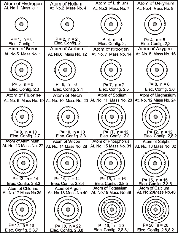
Electronic configuration of atoms
When an atom gives up an electron it acquires a positive charge (+) and when it acquires an electron it becomes negatively charged (–). This can be illustrated with a simple example.
Na – 1e– = Na+
Cl + 1e– = Cl–
In both the examples a stable configuration of 8 electrons (in the last orbit) is obtained. This is the reason why Sodium (Na) and Chlorine (Cl) react vigorously to produce Sodium Chloride (NaCl). The transfer of electrons from one atom to another gives rise to another important term often used in chemistry: Chemical Bond.
In the periodic table the elements are listed in a prescribed format. Besides the obvious grouping of atomic weights the other major criterion used is the number of electrons in the last shell. This is why Lithium, Sodium, and Potassium, appear in the same column (each has one electron in its last orbit).
It is now evident why elements react and why Sodium and Potassium will not react chemically as both of them want to get rid of an electron to obtain stability. It can therefore be concluded that a chemical reaction will most likely take place between an element that wants to get rid of an electron and one that wants to receive an electron. In the example stated above Sodium wants to give up an electron and Chlorine wants to receive an electron. This is the reason that when these two elements come into contact with each other they react vigorously.
2.3 Balancing chemical equations
The first step to balancing equations is to write the chemical components in the form that they exist in nature symbolically. A balanced chemical equation follows the Law of Conservation of Mass and hence to deem an equation balanced the amount of each element reacting must give rise to an equal amount of the same element in the new formed compound. This must be done before the equation can be used in a chemically meaningful way.
A balanced equation has equal numbers of each type of atom on each side of the equation. The Law of Conservation of Mass is the rationale for balancing a chemical equation. Here is the example equation for this lesson:
H2 + O2 —> H2O
It is an unbalanced equation (sometimes also called a skeleton equation). This means that there are unequal numbers on at least one atom on each side of the arrow.
In the example equation, there are two atoms of hydrogen on each side, but there are two atoms of oxygen on the left side and only one on the right side.
A balanced equation must have equal numbers of each type of atom on both sides of the arrow.
An equation is balanced by changing coefficients in a somewhat trial-and-error fashion. It is important to note that only the coefficients can be changed, never, a subscript. The coefficient times the subscript gives the total number of atoms.
Sample problem
As a sample exercise, consider the equation given below. To determine whether this reaction is balanced you must first determine how many atoms of each type are on the reactant side (left-hand side) of the equation and how many atoms of each type are on the product side (right-hand side).

In this example, you have two nitrogen atoms and two hydrogen atoms on the reactant side but only one nitrogen atom and three hydrogen atoms on the product side. For balancing the equation, we are not concerned what molecules these atoms are in, just the number of atoms of each type.
To balance this reaction, it is best to choose one kind of atom to balance initially. Let’s choose nitrogen in this case. To obtain the same number of nitrogen atoms on the product side as on the reactant side requires multiplying the number of product NH3 molecules by two to give:

As you can see above, once we know what the molecules are (N2, H2, and NH3 in this case) we cannot change them (only how many of them there are). The nitrogen atoms are now balanced, but there are six atoms of hydrogen on the product side and only two of them on the reactant side. The next step requires multiplying the number of hydrogen molecules by three to give:

As a final step, make sure to go back and check whether you indeed have the same number of each type of atom on the reactant side as on the product side. In this example, we have two nitrogen atoms and six hydrogen atoms on both sides of the equation. We now have a balanced chemical equation for this reaction
2.4 Chemical periodicity
Lothar Meyer and Dimitri Mendeleev both discovered meaningful patterns of properties among the approximately 63 elements known in 1865.Both listed the elements in order of increasing atomic weight and saw that the properties repeat, a phenomenon called periodicity.
Mendeleev offered some bold, but correct, proposals about places in the scheme that seemed inconsistent and so is generally given credit for the development of the periodic table. Mendeleev’s periodic table left holes where a known element would not properly fit. The classic example is germanium, which was unknown. There was no element in the group that fits the properties of the element below silicon and to the left of arsenic. Mendeleev left that position empty and proposed that the element that belonged there, which he called eka-silicon, was simply yet to be discovered. Within a few years, it was found and its properties matched Mendeleev’s predictions almost perfectly.
At the time of Mendeleev, scientists did not know about the structure of the atom and about subatomic particles and so they did know about atomic numbers. It is a universal fact that the atomic number is the number of protons in the nucleus and therefore it is the charge of the nucleus. The periodic table is actually arranged in order of increasing atomic number, not increasing atomic weight.
A periodic table is included in Appendix -A for reference.
2.4.1 Ionization energy
The ionization energy, IE, is the energy required to remove the outermost electron from a gaseous atom or ion. The first ionization energy, IE1, is the energy for the removal of an electron from a neutral, gaseous atom: M (g) M(g)+ + e. Metallic atoms tend to lose enough electrons to gain the electron configuration of the proceeding noble gas.
There are periodic trends in the ionization energies, also tied to the effective nuclear charge. As the effective nuclear charge increases, it requires more energy to remove the outermost electron from an atom. Consequently, ionization energy is also related to the atomic radius, with ionization energy increasing as atomic radius decreases. Therefore, the first ionization energy increases from left to right in a period and from bottom to top in a group.
2.4.2 Electron affinities
Electron affinity, E, is the energy change of the reaction of adding an electron to a gaseous atom or ion.: M(g) + e M(g)–. These reactions tend to be exothermic and so the values of E are generally negative.
In general, electron affinity tends to decrease (become more negative) from left to right in a period. Going down a group, there is little change in the electron affinities. Negative electron affinity means that the atom gains electrons easily.
2.4.3 Sizes of ions
Recall that atoms increase in size going from right-to left on a period and top-to-bottom in a group.
Cations are smaller than their parent atom because the effective nuclear charge on the outermost electrons is greater in the cation. The number of protons remains the same but the number of screening electrons decreases.
Anions are larger than their parent atoms because the effective nuclear charge on the outermost electrons in smaller in the anion. The number of protons remains the same but the number of screening electrons increases.
Isoelectronic series are groups of atoms and ions which have the same electronic configuration. Within isoelectronic series, the more positive the charge, the smaller the species and the more negative the charge, the larger the species.
Having understood the fundamental way in which atoms react we will now look at how a chemical engineer uses this information to determine reactions, quantities and product values in the field.
2.5 Molecular weight
The molecular weight of a substance is the weight in atomic mass units of all the atoms in a given formula.
An atomic mass unit is defined as 1/12 the weight of the carbon-12 isotope. The old symbol was amu, while the most correct symbol is u (a lower case letter u).
Carbon-12 is defined as weighing exactly 12 amu. This is the starting point for how much an atom weighs.
The molecular weight of a substance is needed tell us how many grams are in one mole of that substance.
The mole is the standard method in chemistry for communicating how much of a substance is present.
The four steps used to calculate a substance’s molecular weight are mentioned below:
Step One: Determine how many atoms of each different element are in the formula.
Step Two: Look up the atomic weight of each element in a periodic table.
Step Three: Multiply step one times step two for each element.
Step Four: Add the results of step three together and round off as necessary.
2.6 The mole and molar mass
The mole is the standard method in chemistry for communicating how much of a substance is present.
Here is how the International Union of Pure and Applied Chemistry (IUPAC) defines “mole:”
The mole is the amount of substance of a system which contains as many elementary entities as there are atoms in 0.012 kilogram of carbon-12. When the mole is used, the elementary entities must be specified and may be atoms, molecules, ions, electrons, other particles, or specified groups of such particles.
One mole contains as many entities as there are in 12 grams of carbon-12 (or 0.012 kilogram). There are 6.022 x 10²³ atoms in 12 grams of carbon-12. This number has been very carefully measured in a number of ways over many decades.
Avogadro’s number
6.022 x 10²³ is so important that it has a name. It is called Avogadro’s number and has the symbol N. It is so named in honor of Amedeo Avogadro, an Italian chemist, who, in 1811, made a critical contribution (recognized only in 1860 after his death) which helped greatly with the measurement of atomic weights.
2.7 Percent composition
Percent composition is the percent by mass of each element present in a compound.

Consider Water (H2O) for an example.
One mole of water is 18.0152 grams.
In that compound, there are two moles of H atoms and 2 x 1.008 = 2.016 grams. That’s how many grams of hydrogen are present in one mole of water.
There is also one mole of oxygen atoms weighing 16.00 grams in the mole of water.
To get the percentage of hydrogen, divide the 2.016 by 18.015 and multiply by 100, giving 11.19%.
For oxygen it is 16.00 ÷ 18.015 = 88.81%.
2.7.1 Molar ratios
The molar ratio will assume a place of central importance in solving stoichiometric problems. The sources for these ratios are the coefficients of a balanced equation.
Consider a sample equation:
2 H2 + O2 —> 2 H2O
What is the molar ratio between H2 and O2?
Answer: two to one. So this ratio in fractional form is: 2 / 1
What is the molar ratio between O2 and H2O?
Answer: one to two. As a fraction, it is: 1/ 2
2.7.2 Mole-mole problems
The procedure used below involves making two ratios and setting them equal to each other. This is called a proportion. One ratio will come from the coefficients of the balanced equation and the other will be constructed from the problem. The ratio set up from data in the problem will almost always be the one with an unknown in it.
It is then possible to cross-multiply and divide to get the answer.
Consider the equation:
N2 + 3 H2 —> 2 NH3
Problem: If we have 2.00 mol of N2 reacting with sufficient H2, how many moles of NH3 will be produced?
Solution
The ratio from the problem will have N2 and NH3 in it.
How is it possible to know which number goes on top or bottom in the ratios? Answer: it does not matter, except that you observe the next point all the time.
When making the two ratios, be 100% certain that numbers are in the same relative positions. For example, if the value associated with NH3 is in the numerator, then MAKE SURE it is in both numerators.
Use the coefficients of the two substances to make the ratio from the equation.
Why isn’t H2 involved in the problem? Answer: The word “sufficient” removes it from consideration.
Let’s use this ratio to set up the proportion: NH3/ N2
That means the ratio from the equation is: 2 / 1
The ratio from the data in the problem will be: x / 2
The proportion (setting the two ratios equal) is: x / 2 = 2 / 1
Solving by cross-multiplying gives x = 4.00 mol of NH3 produced.
2.7.3 Mole-mass problems
The solution procedure used below involves making two ratios and setting them equal to each other. This is called a proportion. One ratio will come from the coefficients of the balanced equation and the other will be constructed from the problem. The ratio set up from data in the problem will almost always be the one with an unknown in it.
It is now possible to cross-multiply and divide to get the answer.
However, there is one addition to the above technique. One of the values will need to be expressed in moles. This could be either a reactant or a product. In either case, moles will have to convert to grams or the reverse.
Suppose a specific mass is indicated in a problem. It is required to convert this to moles.
Example – If 80.0 grams of O2 was produced, how many moles of KClO3 decomposed?
The ratio from the above statement is: 3/ 2
The ratio from the data in the problem will be: 2.5 / x
The 2.50 mole came from 80.0 g ÷ 32.0 g/mol. The 32.0 g/mol is the molar mass of O2.
Be careful to keep in mind that oxygen is O2, not just O.
Solving by cross-multiplying and dividing gives x = 1.67 mol of KClO3 decomposed.
2.7.4 Mass-mass problems
This is the most common type of stoichiometric problem. There are four steps involved in solving these problems:
- Make sure calculations are based on a properly balanced equation.
- Convert grams of the substance given in the problem to moles.
- Construct two ratios – one from the problem and one from the equation and set them equal. Solve for “x,” which is usually found in the ratio from the problem.
- Convert moles of the substance just solved for into grams.
Remarks
- Double check the equation. Lots of students go right ahead and solve using the unbalanced equation supplied in the problem (or test question for that matter).
- DON’T use the same molar mass in steps two and four.
- Don’t multiply the molar mass of a substance by the coefficient in the problem BEFORE using it in one of the steps above. For example, if the formula says 2 H2O, DON’T use 36.0 g/mol, use 18.0 g/mol.
- Don’t round off until the very last answer.
A graphical representation is given below.

Mass-Mass Conversion Chart
2.8 Introduction to solutions
A solution is a particular type of mixture. Mixtures in chemistry are combinations of different substances where each substance retains its chemical properties. Generally, mixtures can be separated by non-chemical means such as filtration, heating, or centrifugation.
A solution is a homogeneous mixture where all particles exist as individual molecules or ions. There are homogeneous mixtures where the particle size is much larger than individual molecules. However, the particle size is so small that the mixture never settles out. Terms such as colloid, sol, and gel are used to identify these mixtures.
A solution has two components: the solute and the solvent.
The solvent is the substance in greater amount.
It is usually a liquid, although it does not have to be. It is usually water, but it does not have to be. We will focus on water only and will leave non-aqueous solvents alone.
The solute is the substance in lesser amount.
Molarity
The molarity of a solution is calculated by taking the moles of solute and dividing by the liters of solution.

Dilution: Definition and Calculations
To dilute a solution means to add more solvent without the addition of more solute. Of course, the resulting solution is thoroughly mixed so as to ensure that all parts of the solution are identical. The fact that the solvent amount stays constant allows us to develop calculation techniques.
Moles before dilution = moles after dilution
From the definition of molarity, the moles of solute equals the molarity times the volume.
Hence it is now possible to substitute MV (molarity times volume) into the above equation, like this:
M1V1 = M2V2
In the following sections we will review the other measurements that a chemical engineer uses in a process plant.
2.9 Units and dimensions
A measured or numbered quantity has a numerical value and a unit associated with it. It is useful and essential in most engineering calculations to specify both the parameters appearing in an equation. A dimension is a property that can be measured, such as length, time, mass or temperature. Alternatively, it is obtained by multiplying or dividing other dimensions; such as length/time (velocity), length3 (volume), or mass/length3 (density). Measurable units are specific values of dimensions that are outlined by conventions, custom or law, such as mass (grams), time (seconds), or feet (centimeters) etc. Units are similar to algebraic variables when quantities are added, subtracted, multiplied or divided. The numerical values of two quantities may be added or subtracted only if the units are the same. Numerical values and their corresponding units can be combined by multiplication or division.
2.9.1 Systems of units
A system of units comprises the following components:
Base units or units
These units indicate the dimensions of mass, length, temperature, time, electrical current and light intensity.
Multiple units
They are defined as multiples or fractions of base units such as minutes, hours and milliseconds, all of which are defined in terms of the base unit of a second. Multiple units are defined for convenience rather than necessity.
Derived units
They are obtained in one of two ways:
- By multiplying and dividing base or multiple units (cm2, ft/min, kg m/s2, etc). Derived units of this type are commonly referred to as compound units
- As defined equivalents of compound units (e.g. 1 erg = 1g cm/s2)
During the 1960’s, an international conference proposed a system of metric units that is widely accepted in the scientific and engineering field. It is known as the “Systeme Internationale d’Unites,” or the SI system for short. Unit prefixes are used in the SI system to indicate powers of ten. The CGS (Centimeter, Gram, Second) system is almost identical to the SI system; the main difference being that grams (g) and centimeters (cm) are used instead of kilograms and meters as the base units of mass and length. The base units of the American engineering system are the foot (ft) for length, the pound mass (lbm) for mass and the second (s) for time.
2.9.2 Conversion of units
A measured quantity can be defined in terms of any units having the suitable dimensions. The equivalence between two expressions of a given quantity may be expressed in terms of a ratio. For example, velocity can be expressed in terms of ft/sec, miles/hr, or any other ratio of a length unit to a time unit. The numerical value of the velocity then is based on the unit chosen.

Ratios as described above are known as conversion factors.
To convert a quantity expressed in terms of one unit to its equivalent in terms of another unit, multiply the given quantity by the conversion factor (new unit /old unit).


2.9.3 Force and weight
Newton’s second law of motion states that force is proportional to the product of mass and acceleration (length/time2). Natural unit of force is therefore, kg m/s2 (SI), g cm/s2 (CGS) and lbm. ft/s2 (American engineering).

The equation which connects force in defined units to mass and acceleration is
F = ma / gc
The weight of an object is the force exerted on the object by the gravitational attraction of the earth. Consider an object of mass m, is subjected to a gravitational force W (W is by definition the weight of the object). If this object were falling freely its acceleration would be g. The weight, mass and free fall acceleration of the object are related by the following equation:
W = mg / gc
The value of g at sea level and 450 latitude and corresponding value of g/gc are given below in each system of units:
g = 9.8066 m/s2 => g/gc = 9.8066 N/kg
g = 980.66 cm/s2 => g/gc = 980.66 dyne/g
g = 32.174 ft / s2 => g/gc = 1 lbf / lbm
2.9.4 Dimensional homogeneity and dimensionless quantities
Every valid equation must be dimensionally homogeneous which means, all additive terms on both sides of the equation must have the same units.
A dimensionless quantity can be a pure number (e.g. 2, 3.5) or a multiplicative combination of variables with no net units:
M (g) / M0 (g)
Quantity like (M/M0) is called a dimensionless group.
Certain important dimensionless numbers are mentioned below.
- Archimedes Number
- Arrhenius Number
- Bingham Number
- Capillary Number
- Cavitation Number
- Darcy friction factor
- Drag Coefficient
- Elasticity Number
- Fourier Number
- Heat Transfer Factor
- Mass Transfer Factor
- Reynolds Number
2.9.5 Arithmetic calculations
- A rule of thumb is that when two or more quantities are combined by multiplication and/or division, the number of significant figures in the result should equal the lowest number of significant figures of any of the multiplicants or divisors
- The rule is that when two or more numbers are added or subtracted, the positions of the last significant figures of each number should be compared. Of these positions, the one farthest to the left is the position of the last permissible significant figure of the sum
- The logic behind rounding off numbers in which the digit to be dropped is a 5, is always to make the last digit of the rounded-off number even
e.g. 2.68 => 2.7, 5.34 =>5.3
2.10 Process variables
A process is any operation or series of operations that results in a physical or chemical change in a material or a mixture of materials. The material that enters a process is referred to as the input or feed to the process and that which leaves is called the output or product. A process unit is a device in which one of the operations that constitutes a process is carried out. Each process unit has associated with it a set of input and output process streams, which consists of the materials that enter and leave the unit.
The process variable is a set of quantities that defines the operating conditions of a reactor or a system of reactors.
2.10.1 Mass and volume
The density of a substance is the mass per unit volume of the substance. The specific volume of a substance is the volume per unit mass of the substance and is therefore the inverse of the density. Densities of pure solids and liquids are relatively independent of temperature and pressure and may be found in standard references (such as the Chemical Engineers’ Handbook).
The specific gravity (SG) of a substance is the ratio of the density ρ of the substance to the density ρref of a reference substance at a specific condition.
SG = ρ / ρref
2.10.2 Flow rate
Mass and volumetric flow rate
Continuous processes involve the movement of material from various process units. The rate, at which material is transported through a process line, is the flow rate of that material.
The flow rate of a process stream may be expressed as a mass flow rate (mass/time) or as a volumetric flow rate (volume/time). Consider a fluid (gas or liquid) which flows in a cylindrical pipe as shown in Figure 2.5, where the shaded area represents a section perpendicular to the direction of flow.
If the mass flow rate of the fluid is m (kg/sec), then every second m kilograms of the fluid pass through the cross section. If the volumetric flow rate of the fluid at the given cross-section is V (m3/sec), then every second V cubic meters of the fluid pass through the cross section. However, the mass m and the volume V of a fluid (in this case, the fluid that passes through the cross section each second) are not independent quantities but are related through the fluid density ρ:
ρ = m / V

Mass and Volumetric Flow rate
2.10.3 Pressure
Fluid pressure and hydrostatic head
A pressure is the ratio of a force to the area on which it acts. Accordingly, pressure units are force units divided by area units (e.g. N/m2, dynes/cm2….). The SI pressure unit (N/m2) is called a Pascal (Pa).
Consider a fluid (gas or liquid) contained in a closed vessel or flowing through a pipe and suppose that a hole of area A is made in the wall of the containing vessel, as in Figure 2.6. The fluid pressure may be defined as the ratio (F/A), where F is the minimum force that would have to be exerted on a plug in the hole to keep the fluid from emerging.

Fluid Pressure in Tank and a pipe
Consider a vertical column of fluid is h meters high and has a uniform cross sectional area A(m2) Fig 3.3. Further, assume that the fluid has a density of ρ(kg / m3) and that a pressure po (N/m2 ) is exerted on the upper surface of the column. The pressure P of the fluid at the base of the column is called the hydrostatic pressure of the fluid (F/A). F thus equals the force on the top surface plus the weight of the fluid in the column.
P = P0 + ρ(g/gc) h

Pressure at the Base of a Fluid Column
2.10.4 Temperature
The temperature of a substance in a particular state (solid, liquid or gas) is a measure of the average kinetic energy held by the molecules.
The two most common temperature scales are defined using the freezing point (Tf ) and boiling point (Tb) of water at a pressure of 1 atmosphere.
Celsius (or centigrade) scale: Tf is assigned a value of 0°C and Tb is assigned a value of 1000C. Absolute zero (theoretically the lowest temperature that can be reached in nature) on this scale falls at -273.15°C.
Fahrenheit scale: Tf is assigned a value of 32°F and Tb is assigned a value of 212°F. Absolute zero falls at –459.67°F.
The Kelvin and Rankine scales are defined such that absolute zero has a value of 0 and the size of a degree is the same as a Celsius degree (Kelvin scale) or a Fahrenheit degree (Rankine scale).
The following relationships may be used to convert a temperature expressed in one defined scale unit to its equivalent in another.
T(K) = T(°C) + 273.15
T(°R) = T(°F) + 459.67
T(°R) = 1.8T(K)
T(°F) = 1.8T(°C) + 32
A degree is to denote both a temperature and its interval.
Consider the temperature interval from 0°C to 5°C. There are nine Fahrenheit and Rankine degrees in this interval and only five Celsius and Kelvin degrees. An interval of 1 Celsius or Kelvin degree therefore contains 1.8 Fahrenheit or Rankine degrees, leading to these conversion factors:
1.8°F / 1°C
1.8°R / 1K
1°F / 1°R
1°C/ 1K
3.1 Chemical reactions – Basic concepts
A chemical reaction is a process in which material changes from a beginning mass to a resulting substance. The significance of a chemical reaction is that new material or materials are produces along with the disappearance of the mass that changed to make the new. This does not mean that new elements have been made. In order to make new elements, the nuclear contents must change. There are magnitudes of difference in the amounts of energy in ordinary chemical reactions compared to nuclear reactions; the rearrangement of the nuclei of atoms to change to new elements is enormous compared to the smaller energies of chemical changes. A chemical equation is a best method to describe what goes on in a chemical reaction.
3.1.1 Examples of chemical changes
Chemical reactions, also called chemical changes, are not limited to happening in a chemistry lab. Here are some examples of chemical reactions with the corresponding chemical equations:
An iron bar rusts
The iron reacts with oxygen in the air to make rust.

Methane burns
Methane combines with oxygen in the air to make carbon dioxide and water vapor.

As a general rule, biochemical process makes poor examples of basic chemical reactions because the actual reaction is carried on within living things and under enzyme control.
3.1.2 Examples of physical changes
Here are some examples of changes that are not chemical reactions. In each case, physical processes may reclaim the original material or materials.
- Water boils out of a kettle or condenses on a cold glass
- An aluminum pot is put on a burner and gets hot
- Dry ice goes from a solid to a gaseous form of carbon dioxide (sublimation)
- Gold melts or solidifies
- Sand is mixed in with salt
- A piece of chalk is ground to dust
- Glass breaks
- An iron rod gets magnetized
- A lump of sugar dissolves in water
3.2 Classification of chemical reactions
Chemists have identified millions of different compounds and an equal number of chemical reactions to form them. When scientists are confronted with an overwhelming number of things, they tend to classify them into groups, in order to make them easier to study and understand. One popular classification scheme for chemical reactions breaks them up into five major categories or types.
3.2.1 Synthesis (Also called direct combination)
A synthesis reaction involves two or more substances combining to make a more complex substance. The reactants may be elements or compounds, and the product will always be a compound. The general formula for this type of reaction can be shown as:
A + B —> AB
or
Element or compound + element or compound –> compound
Some examples of synthesis reactions are shown below;
2H2(g) + O2(g) —-> 2H2O(g)
C(s) + O2(g) —-> CO2(g)
CaO(s) + H2O(l) —-> Ca(OH)2(s)
3.2.2 Decomposition
In a decomposition reaction, one substance is broken down into two or more, simpler substances. This type of reaction is the opposite of a synthesis reaction, as shown by the general formula below;
AB —-> A + B
or
Compound —> element or compound + element or compound
Some examples of decomposition reactions are shown below;
C12H22O11(s) —-> 12C(s) + 11H2O(g)
Pb(OH)2(cr) —-> PbO(cr) + H2O(g)
2Ag2O(cr) —-> 4Ag(cr) + O2(g)
3.2.3 Single displacement (Also called single replacement)
In this type of reaction, a neutral element becomes an ion as it replaces another ion in a compound. The general form of this equation can be written as;
In the case of a positive ion being replaced:
A + BC —-> B + AC
or
In the case of a negative ion being replaced:
A + BC —-> C + BA
In either case we have;
element + compound —-> element + compound
Some examples of single displacement reactions are shown below:
Zn(s) + H2SO4(aq) —-> ZnSO4(aq) + H2(g)
2Al(s) + 3CuCl2(aq) —> 2AlCl3(aq) + 3Cu(s)
Cl2(g) + KBr(aq) —-> KCl(aq) + Br2(l)
3.2.4 Double displacement (Also called double replacement)
Like dancing couples, the compounds in this type of reaction exchange partners. The basic form for this type of reaction is shown below;
AB + CD —-> CB + AD
or
Compound + Compound —-> Compound + Compound
Some examples of double displacement reactions are shown below;
AgNO3(aq) + NaCl(aq) —-> AgCl(s) + NaNO3(aq)
ZnBr2(aq) + 2AgNO3(aq) —-> Zn(NO3)2(aq) + 2AgBr(cr)
H2SO4(aq) + 2NaOH(aq) —-> Na2SO4(aq) + 2H2O(l)
3.2.5 Combustion
When organic compounds like propane are burned, they react with the oxygen in the air to form carbon dioxide and water. The reason why these combustion reactions will stop when all available oxygen is used up is because oxygen is one of the reactants. The basic form of the combustion reaction is shown below:
hydrocarbon + oxygen —-> carbon dioxide and water
Some examples of combustion reactions are:
CH4(g) + 2O2(g) —-> 2H2O(g) + CO2(g)
2C2H6(g) + 7O2(g) —-> 6H20(g) + 4CO2(g)
C3H8(g) + 5O2(g) —-> 4H2O(g) + 3CO2(g)
3.3 Chemical reaction profile
When the reaction proceeds the reactants decrease in concentration while the products increase in concentration. Consider the following two reactions:
A + B –> C
A + C –> D
Where C is the desired product. Let’s assume that this reaction takes place over a solid catalyst.

Schematic representation of a reaction process
The reaction concentration profile may resemble:

A typical reaction profile
3.4 Classification of reactors
In general, chemical reactors have been broadly classified in two ways:
- According to the type of operation
- According to design features
The former classification is mainly for homogeneous reactions and divides the reactors into batch, continuous, or semi-continuous types. Brief descriptions of these types are as follows.
3.4.1 Batch reactor
This type takes in all the reactants at the beginning and processes them according to predetermined course of reaction during which no material is fed into or removed from the reactor. Usually it is in a form of tank with or without agitation and is used primarily in a small-scale production. Most of the basic kinetic data for reactor design are obtained from the type.

Batch reactor
The Sequencing Batch Reactor (SBR) is a batch process for treating wastewater. This process is capable of achieving biological P removal, nitrification, de-nitrification and BOD5 removal in one reactor.
Sequencing batch reactors are suitable for plants that need flexibility and control or that have limited space available. One bioreactor serves as a multipurpose reactor. Cycles that occur in the SBR process are anaerobic, anoxic, react, settling, decant and idle cycles.
The reactor is also used for settling the mixed liquor and decanting the treated wastewater, thus eliminating the need for a secondary clarifier. The liquid level in the reactor and the cycle time can be varied, allowing for the flexibility required to achieve the various processes. A typical operation consists of three or four cycles per day.

Sequencing Batch Reactor (SBR)
3.4.2 Continuous stirred tank reactor
This reactor consists of a well -stirred tank containing the enzyme, which is normally immobilised. The substrate stream is continuously pumped into the reactor at the same time as the product stream is removed. If the reactor is behaving in an ideal manner, there is total back mixing and the product stream is identical with the liquid phase within the reactor and invariant with respect to time. Some molecules of substrate may be removed rapidly from the reactor, whereas others may remain for substantial periods. The distribution of residence times for molecules in the substrate stream is shown in figure 3.5.
The CSTR is an easily constructed, versatile and cheap reactor, which allows simple catalyst charging and replacement. Its well -mixed nature permits straightforward control over the temperature and pH of the reaction and the supply or removal of gases. CSTRs tend to be rather large as the: need to be efficiently mixed. Their volumes are usually about five to ten time the volume of the contained immobilised enzyme. This, however, has the advantage that there is very little resistance to the flow of the substrate stream, which may contain colloidal or insoluble substrates, so long as the insoluble particles are not able to sweep the immobilised enzyme from the reactor. The mechanical nature of the stirring limits the supports for the immobilised enzymes to materials, which do not easily disintegrate to give ‘fines’ which may enter the product stream. However, fairly small particle (down to about 10 μm diameter) may be used, if they are sufficiently dense to stay within the reactor. This minimises problems due to diffusion resistance.
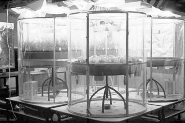
CSTR
Continuous Stirred Tank Reactors (CSTR) for gases (e.g. ozone, carbon dioxide) under defined climate conditions.
Advantages
A continuous process operates at a steady state in which all the variables go to stable value. How fast this steady state is reached depends on the residence time distribution behaviour of the process and this varies from a single mean residence time for a process with ideal plug flow and multiple mean residence times for a fully back mixed reactor like for instance a CSTR. After the steady state is reached, the heat production becomes constant making accurate temperature control much better.
Because of the time independent conversion-space relationship it is possible to fine-tune the exact location and flow rates of additional feeds. In a traditional semi-batch process these additions are generally made on a time based profile because there are not sufficient robust on-line sensors to allow feedback control. For the continuous process, the slower off-line measurements can be used to adjust for instance temperature or feed flow rates. This way, the product properties can be kept constant. This contrasts sharply with a semi-batch process where minor disturbances in the early stages of the reaction (caused by for instance poor temperature control) result in a different conversion-time history and in different product properties because the additions are made at the “wrong” time.
Disadvantages
Emulsion polymerisation can be very sensitive to residence time distribution, especially if particle nucleation is involved. It has been shown that a reactor system with too much back mixing (the ultimate case being a single CSTR) can result in non-steady behaviour. In that case the particle number and the conversion can start to oscillate resulting in a variation in product properties. Even if these oscillations do not occur, the resulting number of particles (and because of this also the volumetric production rate) will be considerably lower.
Another negative effect of residence time distribution is that if a grade change is required also some “twilight” product will be produced which has some intermediate properties and, depending on what change is imposed, has to be considered as waste or low quality product. This limits the flexibility of reactor systems with considerable back-mixing to applications where large amounts of a single grade are required and where the different grades differ only slightly. In all other cases, only a continuous reactor system with near plug flow behaviour will be suitable.
3.4.3 Plug flow reactors (PFR)
The most important characteristic of a PBR is that material flows through the reactor as a plug; they are also called plug flow reactors (PFR). Ideally, the entire substrate stream flows at the same velocity, parallel to the reactor axis with no back -mixing. All material present at any given reactor cross -section has had an identical residence time. The longitudinal position within the PBR is, therefore, proportional to the time spent within the reactor; all products emerging with the same residence time and all substrate molecules having an equal opportunity for reaction

Plug Flow Reactors (PFR)

Cross-section of plug flow reactor
3.4.4 Fluidised bed reactors (FBR)
These reactors generally behave in a manner intermediate between CSTRs and PBRs. They consist of a bed of immobilised enzyme which is fluidised by the rapid upwards flow of the substrate stream alone or in combination with a gas or secondary liquid stream, either of which may be inert or contain material relevant to the reaction. A gas stream is usually preferred, as it does not dilute the product stream. There is a minimum fluidisation velocity needed to achieve bed expansion, which depends upon the size, shape, porosity and density of the particles and the density and viscosity of the liquid. This minimum fluidisation velocity is generally fairly low (about 0.2 – 1.0 cm s-1) as most immobilised-enzyme particles have densities close to that of the bulk liquid. In this case the relative bed expansion is proportional to the superficial gas velocity and inversely proportional to the square root of the reactor diameter.
Fluidising the bed requires a large power input but, once fluidised, there is little further energetic input needed to increase the flow rate of the substrate stream through the reactor figure 3.8. At high flow rates and low reactor diameters almost ideal plug-flow characteristics may be achieved. However, the kinetic performance of the FBR normally lies between that of the PBR and the CSTR, as the small fluid linear velocities allowed by most biocatalyst particles causes a degree of back mixing that is often substantial, although never total.

Fluidized bed reactor
FBRs are chosen where a high conversion is needed but the substrate stream is colloidal or the reaction produces a substantial pH change or heat output. They are particularly useful if the reaction involves the utilisation or release of gaseous material.
Here are some other applications of FBR technology:
- Fertilizers from coal
- Oil Decontamination of sand
- Industrial and municipal waste treatment
- Radioactive waste solidification
3.5 Catalysts
A catalyst is a substance, which changes the rate of a chemical reaction (usually speeding it up), but when the reaction is finished, the catalyst is chemically the same as it was at the beginning. This means that none of it is used up in the reaction
Catalysts are quite substrate-specific, which means that they are only good at changing the rate of one type of chemical reaction and not much good with any others. Catalysts are very important in industry, where it would be uneconomic (or even impossible) to carry out certain chemical reactions.
Examples of industrial processes, which use catalysts that contain transition metals, are:
- Making margarine from vegetable oils (Nickel catalyst)
- Making sulphuric acid (Vanadium catalyst)
- Making ammonia (Iron catalyst)
- Making nitric acid (Platinum catalyst)
- Making sulphur dioxide (Platinum catalyst)
- Making polymers (plastics) (Titanium catalyst)
3.5.1 Classification of catalyst
Homogeneous catalyst
A catalyst in the same phase (usually liquid or gas solution) as the reactants and products is called homogeneous catalyst.
These precious metal compounds and salts are typically used as homogeneous catalysts. The active metal component includes
Palladium
- Good Selectivity
- Suitable Micro porous Structure
- High Strength
- Long Life (over Two Years)

Palladium
Platinum
Platinum is used as a catalytic agent in processing of nitric acid, fertilizers, synthetic fibers, and a variety of other materials. In catalytic processes, the catalyst material is not consumed and can be recycled for future use. This makes chemical demand for platinum quite volatile. Platinum is essential in many of these processes and there are few satisfactory substitutes.

Platinum
Rhodium
Rhodium catalyst gives extremely high activity in hydrogenation of an aromatic compound. It hydrogenates many compounds at room temperature and atmospheric pressure. Normally, a palladium metal catalyst is used for hydrogenation of olefins, but rhodium catalyst gives even higher activity than palladium metal catalyst in this reaction.
Iridium
The iridium catalyst proved to be more stable under a wide range of conditions, and more soluble so that it has no tendency to precipitate out of solution. This means that the catalyst can be continuously recycled within the plant. New catalyst does not need to be added. As well as this iridium is considerably cheaper.
The rarest of the PGMs, iridium is second only to osmium as the densest element and is the most corrosive resistant known. It is white with a yellowish hue.
Although brittle, it is extremely hard (over 4 times that of platinum itself) and with its high melting point, temperature stability and corrosion resistance is used in high-temperature equipment such as the crucibles used to grow crystals for laser technology.
Its biological compatibility is what we owe most to iridium as this enables it to be used in a range of medical and surgical applications. Iridium can be found in health technology combating cancer, Parkinson’s disease, heart conditions and even deafness and blindness.
Its durability prolongs the life of electronic components and products, which exploit iridium’s conductivity and stability.
A shiny, oxidation-resistant metal, iridium also adds to the brilliance and durability of jewels. It also has industrial applications such as the production of chlorine and caustic soda.
Osmium
Osmium is the densest substance known and the hardest of all Platinum Group Metals (PGMs.). It is 10 times harder than platinum itself.
It is these extraordinary qualities that see osmium used in a range of applications in which frictional wear must be avoided, including fountain pen nibs, styluses, and instrument pivots. Especially when alloyed to other PGMs.
Its conductivity means it can be used as a more effective and durable alternative to gold as plating in electronic products.
Like the other PGMs it is an extremely efficient oxidation catalyst and contributes to the environment through use in fuel cells. This quality is also uniquely applied in forensic science for staining fingerprints and DNA (as osmium tetroxide).
Ruthenium
Ruthenium’s catalytic qualities make it a key element in catalysts for fuel cells. Due to its hardness and corrosion resistance, ruthenium is used to coat electrodes in the chloralkali process, which produces chlorine and caustic soda for a wide range of industrial and domestic applications.
In the future, the use of ruthenium in alloys for aircraft turbine blades will help reduce the CO2 impact of air travel on the environment. If current prototypes are successful, their high melting points and high temperature stability will allow for higher temperatures and, therefore, a more efficient burning of aircraft fuel.
Heterogeneous catalysts
Heterogeneous catalysts are sometimes called surface catalysts because they position the reactant molecules on their very surface. Many metals serve as heterogeneous catalysts in which the reactant molecules have an interface between themselves and the catalyst surface. In the reaction known as Hydrogenation, double bonds between carbons accept two hydrogen atoms and use the Pi electrons between the two carbons in order to attach these hydrogen atoms to the carbon atom. The di-atomic Hydrogen molecule attaches itself to the surface of a metal catalyst such as Platinum, Nickel, or Paladium. The double bonded organic molecule does the same. The single bond between the Hydrogen atoms is broken, and so is the Pi bond between the two carbons within the organic molecule broken. The Hydrogen atoms then form a single bond with its single electron and one of the two Pi electrons that previously constituted the Pi bond between the two carbon atoms. Once the Hydrogen has been attached the product molecule disengages from the surface only to have fresh reactant molecules take its place upon the surface of the metal. Heterogeneous catalysts are, as a rule, not as efficient as homogeneous catalysts.

Heterogeneous catalyst
Elemental maps showing the distribution of chromium (red), nickel (blue), and copper (green) in heterogeneous catalyst pellet.
Auto catalyst
An auto catalyst is a cylinder of circular or elliptical cross section made from ceramic or metal formed into a fine honeycomb and coated with a solution of chemicals and platinum group metals. It is mounted inside a stainless steel canister (the whole assembly is called a catalytic converter) and is installed in the exhaust line of the vehicle between the engine and the silencer (muffler).
Vehicle exhaust contains a number of harmful elements, which can be controlled by the platinum group metals in auto catalysts.
The major exhaust pollutants are:
- Carbon monoxide, which is a poisonous gas
- Oxides of nitrogen, which contribute to acid rain, low level ozone and smog formation and which exacerbate breathing problems
- Hydrocarbons, which are involved in the formation of smog and have an unpleasant smell
- Particulate, which contains known cancer-causing compounds
Auto catalysts convert over 90 per cent of hydrocarbons, carbon monoxide and oxides of nitrogen from gasoline engines into less harmful carbon dioxide, nitrogen and water vapour. Auto catalysts also reduce the pollutants in diesel exhaust by converting 90 per cent of hydrocarbons and carbon monoxide and 30 to 40 per cent of particulate into carbon dioxide and water vapor.
3.6 Promoters
Promoters are not catalysts by themselves but increase the effectiveness of a catalyst. For example, alumina Al2O3, is added to finely divided iron to increase the ability of the iron to catalyze the formation of ammonia from a mixture of nitrogen and hydrogen. A poison reduces the effectiveness of a catalyst. For example, lead compounds poison the ability of platinum as a catalyst. Thus, leaded gasoline shall not be used for automobiles equipped with catalytic converters.
3.6.1 Enzymes – the biological catalysts
When a catalyst is doing its job in a living thing, this kind of catalyst is called an Enzyme. Many of the reactions in catabolism are favorable. This means that these reactions will occur spontaneously even outside of a living organism. The problem is, they are way too slow to be of any use in a biological system. If cells did not have ways of speeding up catabolism, life would be nearly impossible. Enzymes accelerate almost all biological reactions.
Enzymes (biological catalysts) are used in the baking, brewing and dairy industries.
Beverages
Beer and lager are alcoholic drinks made in the following way:
- A source of sugar (barley) is added to water and allowed to grow (barley is a plant!). Enzymes in the mixture start to make sugars
- The mixture is then flavoured with hops
- After a bit of a technical process, this mixture has yeast (a living fungus and there are lots of them) added to it
- The yeast ‘eats’ the sugar and gives out alcohol as a waste product
Baking
Bread is a food made in the following way:
Flour, water, salt, yeast and other ingredients (to give flavour) are mixed together to give ‘dough’. The dough is left to ‘rise’. Both of the reactions described above start to happen. The carbon dioxide gas bubbles get trapped in the dough and it starts to get a bit bigger (a bit like a balloon). Alcohol is also made in the dough. Then the dough is ‘kneaded’ to get rid of any big gaps. It may be allowed to rise again, followed by kneading again. The dough is shaped and ‘baked’ at over 100°C. During the baking, the yeast is killed (remember, it starts as a living fungus), the alcohol evaporates away (no getting drunk on bread then!) and sugars remain, giving extra flavour to the bread once it has cooled. Fermentation takes place from when the flour and yeast meet, right up to the temperature at which the yeast dies (about 46°C).
When milk ‘goes off’, this means certain bacteria from around the milk start to multiply, using the milk as a food. The waste materials given out by the bacteria are often nasty and, what’s more, if we drink the milk, the bacteria may multiply in us! Even some harmless bacteria will ‘sour’ milk.
Yoghurt
Milk contains sugar. The bacterium Lactobacillus bulgaricus is added to the milk and its enzymes ferment the sugar (at about 43°C for 4 to 5 hours) into lactic acid. It is this acid the gives yoghurt its pleasant acidic taste. It is also this acid, which stops harmful bacteria from multiplying. The yoghurt is now more like a watery paste.
Fruit and their juices can be added to give a range of flavoured yoghurts.
Most yoghurt has been pasteurized (heated to the kill the bacteria), but this is not done to ‘live’ yoghurts, which still have the bacteria doing their job.
Another microbe called Streptococcus thermophilus is also present in live yoghurt giving it its creamy flavour. Some yeast may also be present.
Cheese
Traditionally, an enzyme called rennin was taken form the stomach juices of calves. When this enzyme is added to milk, it starts to ‘clot’ (form a paste). If the watery part of the mixture (the ‘whey’) is removed, the part, which is left behind, is the ‘curd’, the raw material of cheese. Salt is then added.
Some specially designed Lactobacillus bacteria are also used instead to make the curd.
There are many cheeses. The curd can be allowed to age slightly to give cream cheeses or it can be squeezed and left much longer to slightly decompose giving Cheddar and Cheshire cheeses. If the curd is left long enough, decomposition goes so far that the cheese starts to turn back into a liquid.
3.6.2 Transition metals as catalysts
The first period of transition metals are represented by these metals:
Sc Ti V Cr Mn Fe Co Ni Cu and Zn
Typical common features among them are the presences of d electrons, and in many of them, and their unfilled d orbital. As a result, transition metals form compounds of variable oxidation states. Thus, these metals are electron banks that lend out electrons at appropriate time, and store them for chemical species at other times.
3.7 Efficiency criteria of a chemical process
In addition to the general economic criteria, there are factors to reflect the efficiency of a chemical process.
Fractional Conversion
It is the fraction of a reactant that has undergone a chemical change at a particular stage of the reaction process.
Yield
The yield of a product is the ratio of the quantity of the product actually obtained to its maximum obtainable quantity.
Selectivity
Total or integral selectivity, is the ratio between the amount of reactant used up in a desired reaction and the total amount of the same reactant used up during the overall reaction.
Throughput and Production Rates
Throughput is the quantity of the product obtained per unit time. The maximum throughput of a chemical plant is normally referred to as its design capacity.
Production rate is defined as the throughput per unit of some quantity characterizing the standard geometry of the equipment, such as its volume, cross-sectional area, etc.
4.1 Introduction
Fluid Mechanics is that section of applied mechanics, concerned with the static and dynamics of liquids and gases.
Knowledge of fluid mechanics is essential for the chemical engineer, because the majority of chemical processing operations are conducted either partially or totally in the fluid phase. The handling of liquids is much simpler, much cheaper, and much less troublesome than the handling of solids. Even in many operations, a solid is handled in a finely divided state so that it stays in suspension in a fluid.
Fluid statics: treats fluids in the equilibrium state of no shear stress
Fluid mechanics: deals with portions of fluid in motion relative to other parts.
4.2 Volumetric properties of fluids
4.2.1 Ideal gas law
The ideal gas law is based on the kinetic theory of gases by assuming that gas molecules have a negligible volume, exert no forces on one another and collide elastically with the walls of their container.
PV= nRT
P = absolute pressure of a gas
V = volume or volumetric flow rate of the gas
n = number of moles or molar flow rate of the gas
R = the gas constant, whose value depends on the units of P, V, n, and T
T = absolute temperature of the gas
The equation may also be written as PV=nRT
Where = (V/n) is the molar volume of the gas.
A gas, whose P-V-T behavior is well represented by the above equation, is said to behave as an ideal gas or perfect gas.
4.2.2 Standard conditions
To perform P-V-T calculations utilizing the ideal gas law requires values of R with different units and it can be made easy by the following method:
PV = nRT
and for a set of arbitrarily chosen reference conditions
PsVs = nsRTs
and then to divide the first equation by the second:
PV / PsVs = nT / nsTs
4.2.3 Ideal gas mixtures
Suppose nA moles of substance A, nB moles of B, nc moles of C, etc are contained in a volume V at a temperature T and total pressure P. The partial pressure pA and partial volume vA of A in the mixture are defined as follows:
pA = The pressure that would be exerted by nA moles of A alone in the same total Volume V at the same temperature T.
vA = The volume that would be occupied by nA moles of A alone at the total pressure P and temperature T of the mixture.
Consider each of the individual mixture components and that the mixture as a whole behaves in an ideal manner (this is the definition of an ideal gas mixture). If there are n moles of all species in the volume V at a pressure P and temperature T, then
PV = nRT
In addition, from the definition of partial pressure,
pAV = nART
Dividing the second equation by the first yields

4.3 Liquid-column manometers
A Manometer is a pressure measuring device .The height, or head, to which a fluid rises in an open vertical tube fixed to an apparatus containing a liquid, is a direct measure of the pressure at the point of attachment.
This principle is applied to liquid column manometers:
- For high vacuums or for high pressures and large pressure differences, the gauge liquid is a high-density liquid, e.g. mercury
- For low pressures and small pressure differences, a low-density liquid is used, e.g. Alcohol, water, or carbon tetrachloride
4.3.1 Types of liquid-column manometers
Open manometer
In the “open” type, air exerts pressure on the liquid in one arm of the U-tube. The difference in liquid level in the two arms is a measure of the gas pressure relative to air pressure.

Open U tube manometer
Closed U tube manometer
The “closed” type of manometer has a vacuum above the liquid in one arm. The pressure measured with an instrument of this type does not depend on the pressure of the air and is called the absolute pressure. This manometer can be used to measure the pressure of the air itself. Such a manometer (one used to measure atmospheric pressure) is called a barometer.
Differential U tube
In some cases, however, the difference between pressures at ends of the manometer tube is desired rather than the actual pressure at the either end. A manometer to determine this differential pressure is known as differential pressure manometer.
Mercury manometer
The mercury manometer employs two mercury reservoirs. The mercury in one reservoir is displaced by gas pressure changes resulting from water-level fluctuations over the orifice. This displacement activates a motor that moves the other reservoir to balance the pressure change. This movement is converted to a shaft rotation for recording.

Mercury manometer
Well type manometer
Well manometers are direct reading device used for process monitoring, general-purpose production testing or laboratory measurement. These instruments may also be used for tank level, flow measurement and leak detection. Well manometers are constructed of aluminum channel, stainless steel end blocks and stainless steel manometer well. The glass tubing is a yoke packed with viton gaskets at each end block and is supported at spaced intervals to prevent distortion. In most cases, the uncertainty of a manometer reading is + 1/2 of the smallest scale graduation. This is due to the human eye’s ability to interpolate between graduations

Well type manometer
Inclined type manometer
Inclined manometers offer greater readability by stretching a vertical differential along an inclined indicating column, giving more graduations per unit of vertical height. This effectively increases the instrument’s sensitivity and accuracy. Scales are typically graduated to the hundredth of an inch.

Inclined type manometer
Mercury barometer
Most barometers are manufactured with a scale calibrated to read the height of a column of mercury in millimeters. The average pressure of the air will support a column of mercury 760 mm high.
4.3.3 Limitations of manometer
- While it can be adapted to measure very small pressure differences, it cannot be used conveniently for large pressure differences – although it is possible to connect a number of manometers in series and to use mercury as the manometric fluid to improve the range
- Some liquids are unsuitable for use because they do not form well-defined menisci. Surface tension can also cause errors due to capillary rise; this can be avoided if the diameters of the tubes are sufficiently large – preferably not less than 15 mm diameter
- A major disadvantage of the manometer is its slow response, which makes it unsuitable for measuring fluctuating pressures
- It is essential that the pipes connecting the manometer to the pipe or vessel containing the liquid under pressure should be filled with this liquid and there should be no air bubbles in the liquid
4.4 Mechanical pressure gauges
Gauges with an elastic measuring element are used extensively to measure pressures in technical applications because they are both robust and easy to handle. These gauges incorporate measuring elements, which deform elastically under the influence of pressure. Mechanical pressure gauges are manufactured with bourdon tube, diaphragm, and bellow and spring elements and are accordingly different. The measuring elements are made of copper alloys, alloyed steels or produced with special materials for specific measuring applications.
Pressures are only measurable in conjunction with a reference pressure. The atmospheric pressure alone serves as reference pressure and the pressure gauge shows how much higher or lower the measured pressure is in relation to the given atmospheric pressure (i.e. an overpressure measuring instrument). The pressure is shown in standard measuring ranges on over 270 degrees on the dial. Liquid filled pressure gauges offer optimal protection against destruction by high dynamic pressure loads or vibrations as a result of their cushioning. Switching operations can be carried out when combined with alarm contacts. Electrical output signals (for example, 4…20mA) can be used for industrial process automation in combination with transmitters.
4.4.1 Types of mechanical pressure gauges
Bourdon and Diaphragm Gauges that show both pressure and vacuum indications on the same dial are called compound gauges.
Bourdon-tube gauge
Bourdon tubes are circular-shaped tubes with an oval cross-sectional appearance. The pressure of the media acts on the inside of this tube, which results in the oval cross section becoming almost round. Because of the curvature of the tube ring, the bourdon tube bends when tension occurs. The end of the tube, which is free, moves, thus being a measurement for the pressure. A pointer indicates this movement. Bourdon tubes bent at an angle of approx. 250° are used for measuring pressures up to approximately 60 bar.
For higher pressure, Bourdon tubes are utilized which has a number of superimposed coils of the same diameter (i.e. helical coils) or helical-shaped coils (i.e. helical springs) at one level. Bourdon tubes can only be protected against overload to a limited extent. For specific measuring operations, the pressure gauge can be provided with a chemical seal as a separation or protection system.
The pressure ranges are between 0…0.6 and 0…4000 bar with a reading accuracy (or accuracy class) from 0.1 to 4.0%.

Bourdon gauge
Diaphragm gauge
Diaphragm elements are circular-shaped, convoluted membranes. They are either clamped around the rim between two flanges or welded and exposed t to the pressure of the media acting on one side. The deflection caused in this way is used as a measurement for the pressure and is indicated by a pointer. When compared with bourdon tubes, these diaphragm elements have a relatively high activating force and because of the circular clamping of the element, they are insensitive to vibration. The diaphragm element can be subjected to higher overload through load take-up points (by bringing the diaphragm element against the upper flange).

Diaphragm gauge
The measuring instrument can also be protected against extremely corrosive media by coating with special material or covering with foil. Pressure ranges are between 0…16 mbar and 0…40 bar in accuracy class 0.6 to 2.5.
4.4.2 Pressure gauges with capsule element
The capsule element comprises of two circular-shaped, convoluted membranes sealed tight around their circumference. The pressure acts on the inside of this capsule. A pointer indicates the stroke movement as a measurement of pressure. Pressure gauges with capsule elements are more suitable for gaseous media and relatively low pressures. Overload protection is possible within certain limits. The activating force is increased if a number of capsule elements are connected mechanically in series (a so-called capsule element “package”). Pressure ranges are between 0…2.5 mbar and 0…0.6 bar in the accuracy class 0.1 to 2.5.

Gauge with capsule element
Absolute pressure gauges
These instruments are employed where pressures are to be measured independently of the natural fluctuations in atmospheric pressure. As a rule, all the known types of element and measuring principles can be applied.

Absolute gauge
The pressure of the media to be measured is compared against a reference pressure, which at the same time is absolute zero. For this purpose, an absolute vacuum is given as reference pressure in a reference chamber on the side of the measuring element not subject to pressure. Sealing off the appropriate measuring chamber or surrounding case accomplishes this function. Measuring element movement transmission and pressure indication follow in the same way as with the already described overpressure gauges.
Differential pressure gauges
The difference between two pressures is evaluated directly and shown on the differential pressure gauge. Two sealed medium chambers are separated by the measuring element or measurement elements, respectively. If both operating pressures are the same, the measuring element cannot make any movement and no pressure will be indicated. A differential pressure reading is only given when one of the pressures is either higher or lower. Low differential pressures can be measured directly in the case of high static pressures.

Gauge differential pressure gauge
Very high overload capability is reached with diaphragm elements. The permissible static pressure and the overload capability on the + und – side must be observed. Transmission of the measuring element movement and pressure indication is the same as with the already described overpressure gauges in the majority of cases. Pressure ranges are between 0…16 mbar and 0…25 bar in the accuracy class 0.6 to 2.5.
The typical areas of application are:
- Filter technology (monitoring filter pollution)
- Filling level measurement (in enclosed containers)
- Flow measurement (pressure drop)
4.5 Measurement of fluid flow
Measuring fluid flow is one of the most important factors of process control. In fact, it may well be the most frequently measured process variable.
Different types of meters are used industrially, including:
- Meters based on direct weighing or measurement of volume
- Variable-head meters
- Area meters
- Current meters
- Positive-displacement meters
- Magnetic meters
- Ultrasonic meters
Most widely used for flow measurement are the several types of variable-head meter and area meters.
4.5.1 Variable head meters
Head meters are the most common types of meter utilized to measure fluid flow rates. They measure fluid flow indirectly by creating and measuring a differential pressure by means of an obstruction to the fluid flow. Using well-established conversion coefficients, which depend on the type of head meter used and diameter of the pipe, a measurement of the differential pressure may be translated into a volume rate.
Head meters are simple, reliable, and offer more flexibility than other flow measurement methods. The head-type flow meter usually consists of two components:
- Primary device
The primary devices are placed in the pipe to restrict the flow and develop a differential pressure. The primary device can be selected for compatibility with the specific fluid or application - Secondary devices
The secondary device measures the differential pressure and provides readout or signal for transmission to a control-measuring device is not required in the field. The secondary device can be selected for the type or readout of signal transmission desired
Venturi meter
In this meter, the fluid is accelerated by its passage through a converging cone of angle 15-20°. The pressure difference between the upstream end if the cone and the throat are measured which provide the signal for the rate of flow. The fluid is then retarded in a cone of smaller angle (5-7°) in which large proportion of kinetic energy is converted back to pressure energy. Because of the gradual reduction in the area, there is no vena contracta and the flow area is a minimum at the throat so that the coefficient of contraction is unity.
The attraction of this meter lies in its high-energy recovery so that it may be used where only a small pressure head is available, though its construction is expensive.
To make the pressure recovery large, the angle of downstream cone is small, so boundary layer separation is prevented and friction minimized. Since separation does not occur in a contracting cross section, the upstream cone can be made shorter than the downstream cone with but little friction, and space and material are thereby conserved.
Although venturi meters can be applied to the measurement of gas, they are most commonly used for liquids. Venturi tube applications are generally restricted to those requiring a low-pressure drop and a high accuracy reading. They are widely used in large diameter pipes such as those found in waste treatment plants because their gradually sloping shape will allow solids to flow through it.
Orifice meter
The orifice meter consists of a flat orifice plate with a circular hole drilled in it. There is a pressure tap upstream from the orifice plate and another just downstream. There are three recognized methods of placing the taps. And the coefficient of the meter will depend upon the position of taps.

Orifice meter
The principle of the orifice meter is identical with that of the venturi meter. The reduction of the cross section of the flowing stream in passing through the orifice increases the velocity head at the expense of the pressure head, and the reduction in pressure between the taps is measured by a manometer. Bernoulli’s equation provides a basis for correlating the increase in velocity head with the decrease in pressure head.
A practical advantage of this device is that cost does not increase significantly with pipe size.
Flow nozzle
Flow nozzles may be assumed a variation on the venturi tube. The nozzle opening is an elliptical restriction in the flow but with no outlet area for pressure recovery. Pressure taps are located approximately 1/2 pipe diameter downstream and 1 pipe diameter upstream.

Flow nozzle assembly
The flow nozzle is a high velocity flow meter used where turbulence is quite high (Reynolds numbers above 50,000) such as in steam flow at high temperatures. The pressure drop of a flow nozzle falls between that of the venturi tube and the orifice plate (30 to 95 percent).
Pitot tube
The pitot tube is a device to measure the local velocity along a streamline. The pitot tube has two tubes: one is static tube (b), and another is impact tube (a). The opening of the impact tube is perpendicular to the flow direction. The opening of the static tube is parallel to the direction of flow. The two legs are connected to the legs of a manometer or equivalent device for measuring small pressure differences. The static tube measures the static pressure, since there is no velocity component perpendicular to its opening. The impact tube measures both the static pressure and impact pressure (due to kinetic energy). In terms of heads, the impact tube measures the static pressure head plus the velocity head.

Pitot tube
The pitot tube measures the velocity of only a filament of liquid, and hence it can be used for exploring the velocity distribution across the pipe cross-section. If, however, it is desired to measure the total flow of fluid through the pipe, the velocity must be measured at various distances from the walls and the results integrated. The total flow rate can be calculated from a single reading only of the velocity distribution across the cross-section is already known.
4.5.2 Area meters
These meters consist of devices in which the pressure drop is nearly constant. The area through which the fluid flows varies with the flow rate. The area is related through proper calibration to the flow rate.
Rotameters
Rotameters (also known as variable-area flowmeters) are typically made from a tapered glass tube that is positioned vertically in the fluid flow. A float that is the same size as the base of the glass tube rides upward in relation to the amount of flow. Because the tube is larger in diameter at the top of the glass than at the bottom, the float resides at the point where the differential pressure between the upper and lower surfaces balance the weigh if the float. In most rotameter applications, the flow rate is read directly from a scale inscribed on the glass; in certain cases, an automatic sensing device is used to sense the level of the float and transmit a flow signal. These “transmitting rotameters” are often made from stainless steel or other materials for various fluid applications and higher pressures.

Rotameter principle
It comprises of a gradually tapered glass tube mounted vertically in a frame with the large end up. The fluid flows upward through the tapered tube and freely suspends a float. The float is the indicating element. The entire fluid stream must flow through the annular space between the float and the tube wall. The tube is marked in divisions and the reading of the meter is obtained from the scale reading of the float. A calibration curve must be available to convert the observed scale reading to flow rate. Rotameters can be used for either liquid or gas flow measurements.
Rotameters may range in size from 1/4 inch to greater then 6 inches. They measure a wider band of flow (10 to 1) than an orifice plate with an accuracy of ±2 percent, and a maximum operating pressure of 300 psig when constructed of glass. Rotameters are commonly used for purge flows and levels.
Target meters
In a target meter a sharp-edged disk is fixed at right angles to the direction of flow and the drag force exerted by the fluid is measured. The flow rate is proportional to the square root of this force and to the fluid density. Target meters are rugged and inexpensive and can be used with a variety of fluids, even viscous liquids and slurries. The bar mechanism, however, tends to clog if the solids content of the slurry is high.

Target flow mechanism
Target flowmeters may be used where rough accuracy is required or where the fluid is extremely dirty. A disk or body is immersed into the fluid stream perpendicular to the flow. The differential pressure forces acting on the target are sensed by a strain either gage or force balance method. The magnitude of the strain gage signal or energy required to maintain balance is proportional to the fluid flow. Target flow meters may be used in applications where the flowing fluid has sufficient momentum to cause the required pressure differential.

Target flow meter
The target flowmeter is located where turbulence, pulsation, or vibrations are minimized. If mass flow rate outputs are required, then the target flowmeter requires other readings to infer mass flow. Manual or computer calculations incorporating physical process measurements such as absolute pressure, differential pressure, temperature and viscosity readings must be applied to the output signal to obtain the actual flow rate. These meters typically have a turn down ratio of 10:1.
Vortex-shedding meters
As the fluid flows over a bluff body, vortices are alternately formed downstream on either side of the bluff body. The frequency of the vortices is proportional to the fluid velocity.

Vortex shedding mechanism
Various sensing methods can be applied to measure the frequency of the vortices. If mass flow rate outputs are required, then the vortex shedder flowmeter requires other readings to infer mass flow. Manual or computer calculations incorporating physical process measurements such as absolute pressure, differential pressure, temperature and viscosity readings must be applied to the output signal to obtain the actual flow rate.

Vortex shedding assembly
In a vortex-shedding meter, the “target” is a bluff body, often trapezoidal in cross section. The body is designed to create, when flow is turbulent, a “vortex street” in its wake. Sensors close to the bluff body measure the pressure fluctuations and hence the frequency of the vortex shedding from which the volumetric flow rates may be inferred.
These meters are suitable for many types of fluids, including high-temperature gas and steam. The minimum Reynolds number required for a linear response is fairly high, so the flow rate of high viscous liquids cannot be measured by this type of instrument.

Vortex flow meter
Turbine meters
Turbine flowmeters consist of inlet flow conditioners, rotor, rotor supports, rotor bearings, housing, and signal pick-off coil. A turbine rotor has multiple blades, and the velocity of rotation sensed by the pick-off coil is proportional to flow.

Turbine meter
Turbine flowmeters are sensitive to density and viscosity fluctuations. If mass flow rate outputs are required, then the turbine flowmeter requires other readings to infer mass flow. Manual or computer calculations incorporating physical process measurements such as absolute pressure, differential pressure, temperature and viscosity readings must be applied to the output signal to obtain the actual flow rate. Clean fluids are required to prevent contamination of the bearings unless sealed bearings are used. Turbine meters typically have a turn down ratio of 10:1, but with special care, it is possible to achieve 20:1. Other rotational meters are the propeller, paddle wheel, impeller, rotor and rotating cup flowmeters. They are exceptionally accurate when used under proper conditions but tend to be fragile and their maintenance costs may be high.
4.5.3 Positive displacement meters
Positive Displacement (PD) flow meters measure the volumetric flow rate of a liquid or gas by separating the flow stream into known volumes and counting them over time. Vanes, gears, pistons, or diaphragms are used to separate the fluid. PD flow meters provide good to excellent accuracy and are one of only a few technologies that can be used to measure viscous liquids. Positive displacement flow meters may incorporate oval gears, helical gear, pistons, lobed impeller, sliding vanes, or nutating disks. This type of flow meter entraps a known quantity of fluid per pulse and by totaling up the pulses over time the fluid flow rate is known. If mass flow rate outputs are required, then the positive displacement flow meter requires other readings to infer mass flow. Manual or computer calculations incorporating physical process measurements such as absolute pressure, differential pressure, temperature and viscosity readings must be applied to the output signal to obtain the actual flow rate.
They are very accurate and suitable for clean gases and liquids, even viscous ones. They perform well under high viscosities and can handle dirty liquids or slurries. They are relatively expensive and may be costly to operate.
Reciprocating piston meters
Reciprocating piston meters are of the single and multiple-piston types. The specific choice depends on the range of flow rates required in the particular application. Piston meters can be used to handle a wide variety of liquids. Liquid never encounters with gears or other parts that might clog or corrode.

Reciprocating piston meter
Oval-gear meters
Oval-gear meters have two rotating, oval-shaped gears with synchronized, close fitting teeth. A fixed quantity of liquid passes through the meter for each revolution. Shaft rotation can be monitored to obtain specific flow rates.

Oval gear meter
Rotary-vane meters
Rotary-vane meters are available in several designs, but they all operate on the same principle. The basic unit comprises of an equally divided, rotating impeller (containing two or more compartments) mounted inside the meter’s housing. The impeller is in continuous contact with the casing. A fixed volume of liquid is swept to the meter’s outlet from each compartment as the impeller rotates. The revolutions of the impeller are counted and registered in volumetric units
The Rotary positive displacement gas meters are designed to measure gas volumes with a high degree of accuracy. The measuring chamber is machined out of solid metal so the displaced volume is fixed by the dimensions of the impellers and measuring body. Since the displaced volume is fixed, the accuracy of the meter remains constant over time. The flow of the gas causes the rotation of the impellers.
Nutating-disk meters
Nutating-disk meters have a moveable disk mounted on a concentric sphere located in a spherical side-walled chamber. The pressure of the liquid passing through the measuring chamber causes the disk to rock in a circulating path without rotating about its own axis. It is the only moving part in the measuring chamber.
A pin extending perpendicularly from the disk is connected to a mechanical counter that monitors the disk’s rocking motions. Each cycle is proportional to a specific quantity of flow. As is true with all positive-displacement meters, viscosity variations below a given threshold will affect measuring accuracies. Many sizes and capacities are available. The units can be made from a wide selection of construction materials.
The most common type of displacement flow meter is the nutating disk, or wobble plate meter.
This type of flow meter is normally used for water service, such as raw water supply and evaporator feed. The movable element is a circular disk, which is attached to a central ball. A shaft is fastened to the ball and held in an inclined position by a cam or roller. The disk is mounted in a chamber, which has spherical sidewalls and conical top and bottom surfaces. The fluid enters an opening in the spherical wall on one side of the partition and leaves through the other side. As the fluid flows through the chamber, the disk wobbles, or executes a nutating motion. Since the volume of fluid required making the disc complete one revolution is known, the total flow through a nutating disc can be calculated by multiplying the number of disc rotations by the known volume of fluid.
To measure this flow, the motion of the shaft generates a cone with the point, or apex, down. The top of the shaft operates a revolution counter, through a crank and set of gears, which is calibrated to indicate total system flow. A variety of accessories, such as automatic count resetting devices, can be added to the fundamental mechanism, which performs functions in addition to measuring the flow.

Nutating disc meter
4.5.4 Magnetic meters
Magnetic flow meters follow Faraday’s law of Electromagnetic induction. In a magnetic flowmeter, an electromotive force (flux) is generated perpendicular to the conductive fluid as it passes through a magnetic field in a nonmagnetic conduit. An electromagnet is excited by a pulsed DC either current or sinusoidal AC current. Through ion exchange an electro-motive-force (emf) is produced across an electrode pair, thereby providing the magnetic flowmeter with an emf output signal proportional to the fluid velocity. Magnetic flowmeters are used in conductive liquid applications exclusively. Normally, when installed they provide an unobstructed flow. Typically the minimum conductivity of the fluid is in the order of 0.1 microsiemns/cm so magnetic flowmeters won’t work for most gases and petroleum products. These meters typically have a turn down ratio of 10:1.
Electromagnetic meters
Electromagnetic meters can handle most liquids and slurries, providing that the material being metered is electrically conductive. The flow tube mounts directly in the pipe. Pressure drop across the meter is the same as it is through an equivalent length of pipe because there are no moving parts or obstructions to the flow. The voltmeter can be attached directly to the flow tube or can be mounted remotely and connected to it by a shielded cable

Electro magnetic meter
Electromagnetic meters are used widely in urban and wastewater systems and in industrial applications where a high degree of accuracy is required. They could be used in similar configurations to ultrasonic meters.
Electromagnetic flowmeters have major advantages:
- High degree of accuracy (<0.5%±) and consistent over full flow range when calibrated correctly
- No obstructions to flow
- Robust with only minimal routine maintenance
- They can measure difficult and corrosive liquids and slurries
- They can measure forward as well as reverse flow with equal accuracy
Disadvantages:
- Relatively high cost
- Power supply required
- Electronic components liable to lightning damage
- Repairs require skilled technician and specialized equipment
These meters are non-intrusive. They create no pressure drop in the fluid. The rate of flow is measured from outside the tube. Commercial magnetic meters can measure the velocity of almost all liquids except hydrocarbons, whose electrical conductivity is too small.
4.5.5 Ultrasonic meters
The ultrasonic meter can measure water, wastewater, hydrocarbon liquids, organic or inorganic chemicals, milk, beer, lube oils and the list goes on. The basic requirement is that the fluid is ultrasonically conductive and has a reasonably well formed flow. Clamp-on ultrasonic flowmeters measure flow through the pipe without any contact with the process media, ensuring that corrosion and other effects from the fluid will not affect the workings of the sensors or electronics.
Doppler and transit-time flowmeters are two types of ultrasonic flow meters that have been extensively used in liquid applications. Both transit time and Doppler ultrasonic flowmeters may use clamp-on sensors with their associated assemblies and detect flow rate from the outside of the pipe without stopping the process or cutting through the pipe.
The ultrasonic transducers can be mounted in one of two modes. The upstream and downstream ultrasonic transducers can be installed on opposite sides of the pipe (diagonal mode) or on the same side (reflect mode)

Transducer mounting
The electronics unit will measure internally, the time it takes signals to transmit from one transducer to another. At zero flow, we see no difference in time, but when flow is introduced, time for the transmission of signal from the downstream transducer to the upstream transducer will take longer than the upstream to downstream. Hence, we will see a time differential, which has a relationship with the velocity of the fluid being measured. Knowing the internal diameter of the pipe, we can now calculate a volumetric flow for the liquid.
Obviously there are factors such as solid and liquid refractive angles, error transmissions and poor sonic conductivity at times, but the inbuilt software will normally deal with these by telling us how we should space the transducers and by rejecting erroneous data it receives.
It is important when installing an ultrasonic transit time flow meter to select a location where we would find the most fully formed flow profile, this means that we should avoid bends and try to install our meters on straight runs of pipe. A rule of thumb in the industry is to give at least 10 diameter lengths upstream and 5 lengths downstream. If we are measuring liquids such as water with known properties and sonic velocities, we can further check our measurements by several diagnostic methods. Using the keypad we can see what the actual sonic velocity of water is being measured on our installation. This is one of the simplest and quickest methods.
4.5.6 Coriolis meters
Coriolis meters measure the mass rate of flow directly as opposed to volumetric flow. Because mass does not change, the meter is linear without having to be adjusted for variations in liquid properties. It also eliminates the need to compensate for changing temperature and pressure conditions. The meter is especially useful for measuring liquids whose viscosity varies with velocity at given temperatures and pressures.
Coriolis meters are also available in various designs. A popular unit consists of a U-shaped flow tube enclosed in a sensor housing connected to an electronics unit. The sensing unit can be installed directly into any process. The electronics unit can be located up to 500 feet from the sensor.

Coriolis meters
Inside the sensor housing, the U-shaped flow tube is vibrated at its natural frequency by a magnetic device located at the bend of the tube. The vibration is similar to that of a tuning fork, covering less than 0.1 in. and completing a full cycle about 80 times/sec. As the liquid flows through the tube, it is forced to take on the vertical movement of the tube. When the tube is moving upward during half of its cycle, the liquid flowing into the meter resist being forced up by pushing down on the tube.

U shaped flow tube
Having been forced upward, the liquid flowing out of the meter resists having its vertical motion decreased by pushing up on the tube. This action causes the tube to twist. When the tube is moving downward during the second half of its vibration cycle, it twists in the opposite direction. The amount of twist is directly proportional to the mass flow rate of the liquid flowing through the tube. Magnetic sensors located on each side of the flow tube measure the tube velocities, which change as the tube twists. The sensors feed this information to the electronics unit, where it is processed and converted to a voltage proportional to mass flow rate. The meter has a wide range of applications from adhesives and coatings to liquid nitrogen.
4.5.7 Calorimetric meter
Calorimetric or energy balance thermal mass flowmeters require one heating element and two temperature sensors. Although many design variations exist, they all have a similar operating method. Typically, the heater is attached to the middle of a flow tube with a constant heat input. Two matched RTDs or thermocouples are attached equidistant upstream and downstream of the heater.
The temperature differential at flowing conditions is sensed, producing an output signal. Because both temperature sensors see the same temperature and pressure effects, the design is inherently unaffected by density changes and the result will be a true mass flow output. Limitations of this flowmeter design would commonly be a maximum flow rate of 200 liters per minute, non-industrial packaging, and a tendency to clog in dirty fluids. These meters typically have a turn down ratio of 10:1.

Calorimetric meter
Constant power thermal mass flow meters
Constant power thermal mass flowmeters are thermal (heat loss) mass flowmeters and require three active elements. A constant current heating element is coupled to an RTD. This heated RTD acts a heat loss flow sensor while a second RTD operates as an environmental temperature sensor. When the fluid is at rest the heat loss is at a minimum. Heat loss increases with increasing fluid velocity. In this method of operation the mass of the sensor must change, it’s temperature, making it slow to respond to fluid velocity changes. In addition, this method of operation has a limited useful temperature range due to the constant current applied.

Constant power thermal mass flowmeter
The dynamic temperature range may be widened by applying more power (current) to the heater, but this can result in excessive heat applied to the heater when the fluid is at rest. The effects of variations in density are virtually eliminated by molecular heat transfer and sensor temperature corrections. These meters typically have a turn down ratio of 100:1.
Constant temperature thermal mass flow meters
Constant temperature thermal mass flowmeters are thermal mass flowmeters (heat loss). There are three basic operating methods, which are commonly used to excite the sensor. Constant temperature thermal mass flowmeters require two active sensors (typically platinum RTDs) that are operated in a balanced state. One acts as a temperature sensor reference; the other is the active heated sensor. Heat loss produced by the flowing fluid tends to unbalance the heated flow sensor and it is forced back into balance by the electronics. With this method of operating the constant temperature sensor, only the skin temperature is affected by the fluid flow heat loss. This allows the sensor core temperature to be maintained and produces a very fast response to fluid velocity and temperature changes. Additionally, because the power is applied as needed, the system has a wide operating range of flow and temperature.

Constant temperature thermal mass flowmeter
The heated sensor maintains an index of overheat above the environmental temperature sensed by the unheated element. The effects of variations in density are virtually eliminated by molecular heat transfer and sensor temperature corrections. These meters typically have a turn down ratio of 1000:1 when properly sized.
4.5.8 Open channel meters
The common method of measuring flow through an open channel is to measure the height or HEAD of the liquid as it passes over an obstruction (a flume or weir) in the channel. Using ultrasonic level technology, open channel flow meters include a non-contacting sensor mounted above the flume or weir. By measuring the transit time or time of flight from transmission of an ultrasonic pulse to receipt of an echo, the water level or “Head” is accurately measured.
Flumes and weirs are specially designed channel shapes that characterize the flow of water. The choice of flume or weir type depends on the application: flow rate, channel shape and solids content of the water.
The traditional method to measure flow in man made channels is to introduce a restriction into the section. The liquid flowing in that channel must rise as the flowing volume is constant upstream and downstream of that section. By measuring that rise, the flow rate can be deduced. Such devises are known as flumes and weirs.
Weirs
Weirs operate on the principle that an obstruction in a channel will cause water to back up, creating a high level (head) behind the barrier. The head is a function of flow velocity, and, therefore, the flow rate through the device. Weirs consist of vertical plates with sharp crests. The top of the plate can be straight or notched. Weirs are classified in accordance with the shape of the notch. The basic types are V-notch, rectangular, and trapezoidal
A notch is an opening in the side of a measuring tank or reservoir extending above the free surface. A weir is a notch on a large scale, used, for example, to measure the flow of a river, and may be sharp edged or has a substantial breadth in the direction of flow.

Weirs
Flumes
Flumes are generally used when head loss must be kept to a minimum, or if the flowing liquid contains large amounts of suspended solids. Flumes are to open channels what venturi tubes are to closed pipes. Popular flumes are the Parshall and Palmer-Bowlus designs.

Classification of flumes
The Parshall flume consists of a converging upstream section, a throat, and a diverging downstream section. Flume walls are vertical and the floor of the throat is inclined downward. Head loss through Parshall flumes is lower than for other types of open-channel flow measuring devices. High flows velocities help make the flume self-cleaning. Flow can be measured accurately under a wide range of conditions.
Palmer-Bowlus flumes have a trapezoidal throat of uniform cross section and a length about equal to the diameter of the pipe in which it is installed. It is comparable to a Parshall flume in accuracy and in ability to pass debris without cleaning. A principal advantage is the comparative ease with which it can be installed in existing circular conduits, because a rectangular approach section is not required.
Rectangular and trapezoidal flumes function by having a constriction at the throat and/or a raised invert (bottom) at the throat. Either feature can cause critical flow at the throat in a properly operating flume. These flumes are simpler to construct, can be more easily fit into an existing channel, and can trap less sediment than a Parshall flume. However, the methodology relating discharge to measured head is more complex.
U-flumes, similar to Palmer-Bowles flumes but with a semi-circular throat, are ideal for use in culverts or pipes. Critical flow is achieved by narrowing the throat or by raising the bottom of the flume at the throat. Analysis of U flumes is similar to that of the trapezoidal flume.
Discharge through weirs and flumes is a function of level, so level measurement techniques must be used with the equipment to determine flow rates. Staff gages and float-operated units are the simplest devices used for this purpose. Various electronic sensing, totalizing, and recording systems are also available.
4.5.9 Insertion meters
A few insertion meters measure the average flow velocity but the majority measures the local velocity at one point only.

Insertion meter
4.6 Valves
It is all but impossible to design a practical fluid power system without some means of controlling the volume and pressure of the fluid and directing the flow of fluid to the operating units. This is accomplished by the incorporation of different types of valves. A valve is defined as any device by which the flow of fluid may be started, stopped, or regulated by a movable part that opens or obstructs passage. As applied in fluid power systems, valves are used for controlling the flow, the pressure, and the direction of the fluid flow.
Valves must be accurate in the control of fluid flow and pressure and the sequence of operation. Leakage between the valve element and the valve seat is reduced to a negligible quantity by precision-machined surfaces, resulting in carefully controlled clearances. This is one of the very important reasons for minimizing contamination in fluid power systems. Contamination causes valves to stick, plugs small orifices, and causes abrasions of the valve seating surfaces, which results in leakage between the valve element and valve seat when the valve is in the closed position. Any of these can result in inefficient operation or complete stoppage of the equipment. Valves may be controlled manually, electrically, pneumatically, mechanically, hydraulically, or by combinations of two or more of these methods. Factors that determine the method of control include the purpose of the valve, the design and purpose of the system, the location of the valve within the system, and the availability of the source of power.
Classification of valves
There are three principal types of control valves used in pneumatic/hydraulic systems:
- Flow control
- Pressure control
- Directional control
Some valves have multiple functions that fall into more than one classification.
4.6.1 Flow control valves
Flow control valves are used to regulate the flow of fluids in fluid-power systems. Control of flow in fluid-power systems is important because the rate of movement of fluid-powered machines depends on the rate of flow of the pressurized fluid. These valves may be operated manually, hydraulically, electrically, or pneumatically.
Ball valves
Ball valves, as the name implies, are stop valves that use a ball to stop or start a flow of fluid. As the valve handle is turned to open the valve, the ball rotates to a point where part or all of the hole through the ball is in line with the valve body inlet and outlet, allowing fluid to flow through the valve. When the ball is rotated, the hole is perpendicular to the flow openings of the valve body, the flow of fluid stops.
Most ball valves are the quick-acting type. They require only a 90-degree turn to either completely open or close the valve. However, many are operated by planetary gears. This type of gearing allows the use of a relatively small hand wheel and operating force to operate a large valve. The gearing does, however, increase the operating time for the valve.
Some ball valves also contain a swing check located within the ball to give the valve a check valve feature. There are also three-way ball valves that are used to supply fluid from a single source to one component or the other in a two-component system.
Gate valves
Gate valves are used when a straight-line flow of fluid and minimum flow restriction are needed. Gate valves are so-named because the part that either stops or allows flow through the valve acts somewhat like a gate. The gate is usually wedge-shaped. When the valve is wide open, the gate is fully drawn up into the valve bonnet. This leaves an opening for flow through the valve the same size as the pipe in which the valve is installed. Therefore, there is little pressure drop or flow restriction through the valve.
Gate valves are not suitable for throttling purposes. The control of flow is difficult because of the valve’s design, and the flow of fluid slapping against a partially open gate can cause extensive damage to the valve. Except as specifically authorized, gate valves should not be used for throttling.

Operation of a gate valve
Gate valves are classified as either rising-stem or non rising-stem valves. The stem is threaded into the gate. As the hand wheel on the stem is rotated, the gate travels up or down the stem on the threads while the stem remains vertically stationary. This type of valve will usually have a pointer indicator threaded onto the upper end of the stem to indicate the position of the gate. Valves with rising stems are used when it is important to know by immediate inspection whether the valve is open or closed and when the threads (stem and gate) exposed to the fluid could become damaged by fluid contaminants. In this valve, the stem rises out of the valve when the valve is opened.
Globe valves
Globe valves are probably the most common valves in existence. The inlet and outlet openings for globe valves are arranged in a way to satisfy the flow requirements. Figure 4.34 shows straight-, angle-, and cross-flow valves.

Types of globe valve bodies
The moving parts of a globe valve consist of the disk, the valve stem, and the hand wheel. The stem connects the hand wheel and the disk. It is threaded and fits into the threads in the valve bonnet. The part of the globe valve that controls flow is the disk, which is attached to the valve stem. (Disks are available in various designs.) The valve is closed by turning the valve stem in until the disk is seated into the valve seat. This prevents fluid from flowing through the valve (Figure 4.35 view A).

Operation of a globe valve
The edge of the disk and the seat are very accurately machined so that they form a tight seal when the valve is closed. When the valve is open (Figure 4.35 view B), the fluid flows through the space between the edge of the disk and the seat. Since the fluid flows equally on all sides of the center of support when the valve is open, there is no unbalanced pressure on the disk to cause uneven wear. The rate at which fluid flows through the valve is regulated by the position of the disk in relation to the seat. The valve is commonly used as a fully open or fully closed valve, but it may be used as a throttle valve. However, since the seating surface is a relatively large area, it is not suitable as a throttle valve, where fine adjustments are required in controlling the rate of flow.
The globe valve should never be jammed in the open position. After a valve is fully opened, the hand wheel should be turned toward the closed position approximately one-half turn. Unless this is done, the valve is likely to seize in the open position, making it difficult, if not impossible, to close the valve. Many valves are damaged in this manner. Another reason for not leaving globe valves in the fully open position is that it is sometimes difficult to determine if the valve is open or closed. If the valve is jammed in the open position, the stem may be damaged or broken by someone who thinks the valve is closed, and attempts to open it.
It is important that globe valves be installed with the pressure against the face of the disk to keep the system pressure away from the stem packing when the valve is shut.
Needle valves
Needle valves are similar in design and operation to the globe valve. Instead of a disk, a needle valve has a long tapered point at the end of the valve stem. A cross-sectional view of a needle valve is illustrated in figure 4.36. The long taper of the valve element permits a much smaller seating surface area than that of the globe valve; therefore, the needle valve is more suitable as a throttle valve. Needle valves are used to control flow into delicate gauges, which might be damaged by sudden surges of fluid under pressure. Needle valves are also used to control the end of a work cycle, where it is desirable for motion to be brought slowly to a halt, and at other points where precise adjustments of flow are necessary and where a small rate of flow is desired.

Cross-sectional view of a needle valve
Hydraulic and pneumatic globe valves
The valve consists of a valve body and a stem cartridge assembly. The stem cartridge assembly includes the bonnet, gland nut, packing, packing retainer, handle, stem, and seat. On small valves (1/8 and 1/4 inch) the stem is made in one piece, but on larger sizes it is made of a stem, guide, and stem retainer. The valve disk is made of nylon and is swaged into the stem, either for 1/8- and 1/4-inch valves, or the guide, for larger valves. The bonnet screws into the valve body with left-hand threads and is sealed by an O-ring (including a back-up ring).
The valve is available with either a rising stem or a non-rising stem. The rising stem valve uses the same port body design, as does the non-rising stem valve. The stem is threaded into the gland nut and screws outward as the valve is opened. This valve does not incorporate provisions for tightening the stem packing nor replacing the packing while the valve is in service; therefore, complete valve disassembly is required for maintenance. Figure 4.37 illustrates a rising stem hydraulic and pneumatic globe valve.

Pneumatic globe valve
4.6.2 Pressure control valves
The safe and efficient operation of fluid power systems, system components, and related equipment requires a means of controlling pressure. There are many types of automatic pressure control valves. Some of them merely provide an escape for pressure that exceeds a set pressure; some only reduce the pressure to a lower pressure system or subsystem; and some keep the pressure in a system within a required range.
Relief valves
Some fluid power systems, even when operating normally, may temporarily develop excessive pressure; for example, when an unusually strong work resistance is encountered. Relief valves are used to control this excess pressure. Relief valves are automatic valves used on system lines and equipment to prevent over-pressurization.
Most relief valves simply lift (open) at a preset pressure and reset (shut) when the pressure drops slightly below the lifting pressure. They do not maintain flow or pressure at a given amount, but prevent pressure from rising above a specific level when the system is temporarily overloaded.
Main system relief valves are generally installed between the pump or pressure source and the first system isolation valve. The valve must be large enough to allow the full output of the hydraulic pump to be delivered back to the reservoir. In a pneumatic system, the relief valve controls excess pressure by discharging the excess gas to the atmosphere.
Smaller relief valves, similar in design and operation to the main system relief valve, are used in isolated parts of the system where a check valve or directional control valve prevents pressure from being relieved through the main system relief valve and where pressures must be relieved at a set point lower than that provided by the main system relief.
Figure 4.38 shows a typical relief valve. System pressure simply acts under the valve disk at the inlet to the valve. When the system pressure exceeds the force exerted by the valve spring, the valve disk lifts off its seat, allowing some of the system fluid to escape through the valve outlet until the system pressure is reduced to just below the relief set point of the valve.

Relief valve
All relief valves have an adjustment for increasing or decreasing the set relief pressure. Some relief valves are equipped with an adjusting screw for this purpose. This adjusting screw is usually covered with a cap, which must be removed before an adjustment can be made. Some type of locking device, such as a lock nut, is usually provided to prevent the adjustment from changing through vibration. Other types of relief valves are equipped with a hand wheel for adjusting the valve. Either the adjusting screw or the hand wheel is turned clockwise to increase the pressure at which the valve will open. In addition, most relief valves are also provided with an operating lever or some type of device to allow manual cycling or gagging the valve open for certain tasks
In some hydraulic systems, there is a pressure in the return line. This backpressure is caused by restrictions in the return line and will vary in relation to the amount of fluid flowing in the return line. This pressure creates a force on the back of the valve element and will increase the force necessary to open the valve and relieve system pressure.
4.6.3 Directional control valves
Directional control valves are designed to direct the flow of fluid, at a desired time, to the point in a fluid power system where it will do work. The driving of a ram back and forth in its cylinder is an example of a directional control valve application. Various other terms are used to identify directional control valves, such as selector valve, transfer valve, and control valve. They are ideal for machine tools, production and material handling equipment, marine auxiliary power controls, off-highway and heavy construction equipment, oilfield, and farm equipment.
Directional control valves for hydraulic and pneumatic applications are similar in design and application, with one major difference: the return port of a hydraulic valve is ported through the return line to the reservoir, while the return port of a pneumatic valve is exhausted to the atmosphere. There are a number of valve porting options available, depending upon the needs of a given application.
However, they vary considerably in physical characteristics and operation. The valves may be a:
- Poppet type, in which a piston or ball moves on and off a seat
- Rotary-spool type, in which a spool rotates about its axis
- Sliding-spool type, in which a spool slides axially in a bore
Directional-control valves may also be classified according to the method used to actuate the valve element:
- Hydraulically operated
- Manually (lever or plunger action) operated
- Mechanically (cam or trip action) operated
- Electrically (solenoid action) operated
Directional-control valves may also be classified according to the number of positions of the valve elements or the total number of flow paths provided in the extreme position. For example, a three-position, four-way valve has two extreme positions and a center or neutral position. In each of the two extreme positions, there are two flow paths, making a total of four flow paths.
Poppet valve
It consists primarily of a movable poppet that closes against a valve seat. Pressure from the inlet tends to hold the valve tightly closed. A slight force applied to the poppet stem opens the poppet. The action is similar to the valves of an automobile engine. The poppet stem usually has an O-ring seal to prevent leakage. In some valves, the poppets are held in the seated position by springs. The number of poppets in a valve depends on the purpose of the valve.

Poppet valve
Spool valve
The valve element slides back and forth to block and uncover ports in the housing. Sometimes called a piston type, the sliding-spool valve has a piston of which the inner areas are equal. Pressure from the inlet ports acts equally on both inner piston areas regardless of the position of the spool. Sealing is done by a machine fit between the spool and valve body and sleeve.

Sliding-spool valve
Check valves
Check valves are used to “check” (prevent) flow in one direction while allowing flow in the opposite direction. Check valves are available in a variety of different configurations. They may be installed independently in a line, or they may be incorporated as an integral part of a sequence, counterbalance, or pressure-reducing valve. The valve element may be a sleeve, cone, ball, poppet, piston, spool, or disc. Force of the moving fluid opens a check valve; backflow, a spring, or gravity closes the valve.

Standard check valve
4.7 Fluid moving machinery
Fluids are transported by means of pumps, compressors, fans etc. The methods used to move fluid can be based on two principles:
- Machinery applying direct pressure to the fluid
- Machinery utilizing torque to generate rotation
Many different methods are used to classify pumps:
- Non-positive displacement pumps that discharge liquid in a continuous flow
- Positive displacement pumps that discharge volumes separated by a period of no discharge
- Fixed displacement pump delivers the same amount of fluid on each cycle
- Fixed delivery
- Variable delivery
- Constant volume
- Variable displacement pump is constructed so that the displacement per cycle can be varied
Pumps may also be classified according to the specific design used to create the flow of fluid. Practically all-hydraulic pumps fall within three design classifications:
- Centrifugal
- Rotary
- Reciprocating
4.8 Centrifugal pumps
4.8.1 Working mechanism of a centrifugal pump
A centrifugal pump is one of the simplest pieces of equipment in any process plant. Its purpose is to convert energy of a prime mover (a electric motor or turbine) first into velocity or kinetic energy and then into pressure energy of a fluid that is being pumped. The energy changes occur by virtue of two main parts of the pump, the impeller and the volute or diffuser. The impeller is the rotating part that converts driver energy into the kinetic energy. The volute or diffuser is the stationary part that converts the kinetic energy into pressure energy.
Note: All of the forms of energy involved in a liquid flow system are expressed in terms of feet of liquid i.e. head.
4.8.2 Components of centrifugal pumps
A centrifugal pump has two main components:
- A rotating component comprised of an impeller and a shaft
- A stationary component comprised of a casing, casing cover, and bearings.

Centrifugal pump cross section
4.8.3 Generation of centrifugal force
The process liquid enters the suction nozzle and then into eye (center) of a revolving device known as an impeller. When the impeller rotates, it spins the liquid sitting in the cavities between the vanes outward and provides centrifugal acceleration. As liquid leaves the eye of the impeller a low-pressure area is created causing more liquid to flow toward the inlet. Because the impeller blades are curved, the fluid is pushed in a tangential and radial direction by the centrifugal force. This force acting inside the pump is the same one that keeps water inside a bucket that is rotating at the end of a string. Figure 4.42 depicts a side cross-section of a centrifugal pump indicating the movement of the liquid.
4.8.4 Conversion of kinetic energy to pressure energy
The key idea is that the energy created by the centrifugal force is kinetic energy. The amount of energy given to the liquid is proportional to the velocity at the edge or vane tip of the impeller. The faster the impeller revolves or the bigger the impeller is, then the higher will be the velocity of the liquid at the vane tip and the greater the energy imparted to the liquid.
This kinetic energy of a liquid coming out of an impeller is harnessed by creating a resistance to the flow. The first resistance is created by the pump volute (casing) that catches the liquid and slows it down. In the discharge nozzle, the liquid further decelerates and its velocity is converted to pressure according to Bernoulli’s principle.
Pump curves relate flow rate and pressure (head) developed by the pump at different impeller sizes and rotational speeds. The centrifugal pump operation should conform to the pump curves supplied by the manufacturer. In order to read and understand the pump curves, it is very important to develop a clear understanding of the terms used in the curves.
4.8.5 Cavitation
In designing any installation in which a centrifugal pump is used, careful attention must be paid to check the minimum pressure, which will arise at any point. If this pressure is less than the vapor pressure at the pumping temperature, vaporization will occur and the pump may not be capable of developing the required suction head. Moreover, if the liquid contains gases, these may come out of solution giving rise to packets of gas. This phenomenon is known as cavitation and may result in mechanical damage to the pump as the bubbles collapse. The onset of cavitation is accompanied by a marked increase in noise and vibration as the bubbles collapse, and a loss of head.
4.9 Positive-displacement pumps
Positive-displacement pumps are another category of pumps. Types of positive-displacement pumps are reciprocating, metering, and rotary pumps. Positive-displacement pumps operate by forcing a fixed volume of fluid from the inlet pressure section of the pump into the discharge zone of the pump. These pumps generally tend to be larger than equal-capacity dynamic pumps. Positive-displacement pumps frequently are used in hydraulic systems at pressures ranging up to 5000 psi. A principal advantage of hydraulic power is the high power density (power per unit weight) that can be achieved. They also provide a fixed displacement per revolution and, within mechanical limitations, infinite pressure to move fluids.
4.9.1 Rotary pumps
All rotary pumps have rotating parts, which trap the fluid at the inlet (suction) port and force it through the discharge port into the system. Gears, screws, lobes, and vanes are commonly used to move the fluid. Rotary pumps are positive displacement of the fixed displacement type. Rotary pumps are designed with very small clearances between rotating parts and stationary parts to minimize slippage from the discharge side back to the suction side. They are designed to operate at relatively moderate speeds. Operating at high speeds causes erosion and excessive wear, which results in, increased clearances.
There are numerous types of rotary pumps and various methods of classification. They may be classified by the shaft position—either vertically or horizontally mounted; the type of drive—electric motor, gasoline engine, and so forth; their manufacturer’s name; or their service application. However, classification of rotary pumps is generally made according to the type of rotating element. A few of the most common types of rotary pumps are discussed in the following paragraphs.
Gear pumps
Gear pumps are classified as either external or internal gear pumps. In external gear, pumps the teeth of both gears project outward from their centers. External pumps may use spur gears, herringbone gears, or helical gears to move the fluid. In an internal gear pump, the teeth of one gear project outward, but the teeth of the other gear project inward toward the center of the pump. Internal gear pumps may be either centered or off-centered.

Gear pump
External-gear pumps are used for flow rates up to about 400 m3/hr working against pressures as high as 170 atm. The volumetric efficiency of gear pumps is in the order of 96 percent at pressures of about 40 atm but decreases as the pressure rises.

Internal gear pump
In the internal-gear pump a spur gear, or pinion, meshes with a ring gear with internal teeth. Both gears are inside the casing. The ring gear is coaxial with the inside of the casing, but the pinion, which is externally driven, is mounted eccentrically with respect to the center of the casing. A stationary metal crescent fills the space between the two gears. Liquid is carried from inlet to discharge by both gears, in the spaces between the gear teeth and the crescent.
Lobe pumps
In principle the lobe pump is similar to the external gear pump; liquid flows into the region created as the counter-rotating lobes unmesh. Displacement volumes are formed between the surfaces of each lobe and the casing, and the liquid is displaced by meshing of the lobes. Relatively large displacement volumes enable large solids (nonabrasive) to be handled. They also tend to keep liquid velocities and shear low, making the pump type suitable for high viscosity, shear-sensitive liquids.
The choice of two or three lobe rotors depends upon solids size, liquid viscosity, and tolerance of flow pulsation. Two lobes handle larger solids and high viscosity but pulsates more. Larger lobe pumps cost 4-5 times a centrifugal pump of equal flow and head.

Lobe pump
Screw pumps
A most important class of pump for dealing with highly viscous material is the screw pump. Designs employing one, two and three screws are in use.
Multiple screw pumps operate as follows:
- The displacement volume is opened at the suction as the counter-rotating screws unmesh
- Subsequent meshing of the screws produces a displacement volume bounded by the thread roots, the thread flanks, and the pump casing
- Continued rotation of the screws translate the displacement volume to the pump discharge
- At the pump discharge the volume is displaced by the meshing of the screw ends
In single screw pumps, the fluid is sheared in the channel between the screw and the wall. Flow is produced because of viscous forces. Pressures achieved with low viscosity materials are negligible.

Screw pump
4.9.2 Reciprocating pumps
Reciprocating pumps operate by displacing a fixed volume through the reciprocating motion of either a piston, a diaphragm, or a bellows. In the simplest example, a piston is drawn back in a closed chamber, creating a vacuum which draws in a fixed volume of fluid. The piston then moves forward and expels the fluid. In this way, by either controlling the stroke length of the piston or the piston stroking speed, accurate flow control can be achieved. The reciprocating motion can be supplied by a motor driven eccentric or a liner magnetic drive (solenoid).
Piston pumps typically require seals or close clearances around the piston to operate accurately. This introduces the problems of seal and piston wear, contamination of the pumped fluid by wear particles, and limitations on the material selections for optimum chemical resistance.
The simplest form of the piston pump is the syringe pump, which is designed to accurately meter up to the volume of one full stroke of the syringe. By accurately stepping the piston on a syringe pump, very accurate flow rates in microliters can be obtained. The major disadvantage of this type of pump is that once the syringe is empty, the refill period allows no flow from the pump. Thus, a syringe pump is not suitable in continuous metering applications.
Diaphragm metering pumps eliminate some of the disadvantages of piston style pumps by replacing the piston with a flexible diaphragm. Because the diaphragm is sealed by clamping around the edge, the pump uses no dynamic seals, which can wear, eliminating leakage or contamination of the pumped fluid.
They may be single-cylinder or multi-cylinder design and of the following three types:
- Piston pumps
- Plunger pumps
- Diaphragm pumps

Operation of a liquid diaphragm pump
Diaphragm pump
The diaphragm pump has been developed for handling corrosive liquids and those containing suspensions of abrasive solids. It is in two sections separated by a diaphragm of rubber, leather, or plastics material. In one section, a piston or plunger operates in a cylinder in which a non-corrosive fluid is displaced. The movement of the fluid is transmitted by means of flexible diaphragm to the liquid to be pumped. The only moving parts of the pump that are in contact with the liquid are the valves, and these can be specially designed to handle the material. In some cases, the movement of the diaphragm is produced by direct mechanical action, or the diaphragm may be air actuated.

Diaphragm pump
4.10 Agitation equipment
Liquids are agitated for a number of purposes, depending on the objectives of the process. These include:
- Suspending solid particles
- Blending miscible liquids
- Dispersing a gas through the liquid in the form of small bubbles
- Dispersing a second liquid, immiscible with the first, to form an emulsion or suspension of fine drops
- Promoting heat transfer between the liquid and a coil or jacket
4.10.1 Static or inline mixers
Static mixers consist of a series of mixing elements arranged axially in a pipe or duct and are widely used in the process industry for a large variety of mixing applications. The energy for mixing is derived from the kinetic energy of the fluid stream. Hence, there is an increase in the pressure drop relative to that of empty pipes.
There are several advantages to static mixers:
- No moving parts
- Simple construction
- Lower capital and operating costs
- Lower energy requirements
- Narrow residence time distributions
The main disadvantages of static mixers are increased pressure drop and fouling problems. Though there are numerous static mixer designs, only two of the more common designs are shown below.
Helical mixers
Helical mixers are comprised of a series of mixing elements with the leading edge of one element being perpendicular to the trailing edge of the previous. Each mixing element is a metal or polymeric ribbon with a 180 degree helical twist that measures approximately one and a half pipe diameters in length. These mixers can be used for laminar, transitional, and turbulent flow applications and are suitable for most blending and dispersion processes involving liquids and gases. The mixing elements can be permanently mounted inside a tube or removable to allow for frequent cleaning and inspection.

Helical mixer
High Efficiency Vortex (HEV) mixers
High Efficiency Vortex (HEV) mixers consist of a series of baffles or tabs inclined relative to one another and at an angle relative to the pipe axis. The mixer elements are rotated by 90 degrees and arranged successively in the pipe. This design can be used in all turbulent-flow mixing applications regardless of line shape or size, and has pressure losses 75% less than conventional static mixers. Mixing is achieved by controlled vortex structures generated by the baffle geometry that requires a mixer length less than 2 pipe diameters. Typical applications include low-viscosity liquid-liquid blending processes, as well as gas-gas mixing.

HEV mixer
4.10.2 Dynamic mixers
A dynamic mixer consists of an impeller, mixer shaft, support structure, gear or bearing housing, and a motor. Though side-entry and bottom-entry mixers are occasionally used, most mixers are top-mounted (shown to the left) with the motor and support housing located above the fluid level. The motor power required for proper mixing can range from less than 1 hp for small vessels containing low viscosity fluids to more than 5000 hp when mixing viscous fluids in large vessels. The extent to which fluid mixing occurs is controlled by the design, size, location, and speed of rotation of the impeller. Some of the more common metal fabricated impeller designs are shown below, but other highly efficient designs that incorporate advanced composites are also widely used in industry.

Dynamic mixer
Marine and pitched blade impellers
The marine impeller (left) is the classical design used for axial mixing. This design, often pitched for downward pumping action, provides a uniform discharge and is most often used with low viscosity fluids (less than 1,000 centipoises). In most cases, vessel baffling is required for the optimal performance of this impeller design. A similar design is the pitched blade impeller (right). This design produces axial flow and is well suited for applications requiring high speeds to disperse liquid/solid mixtures in non-baffled vessels.

Marine impeller
Curved and straight blade impeller
The curved blade or backswept turbine (left) is used with highly viscous mixtures where power consumption is a concern or with liquid/brittle solid mixtures. The straight blade turbine (right) is designed for gas/liquid applications requiring high shear at high speeds. Frequently, these two designs produce radial fluid flow and require vessel baffling to achieve optimum performance.
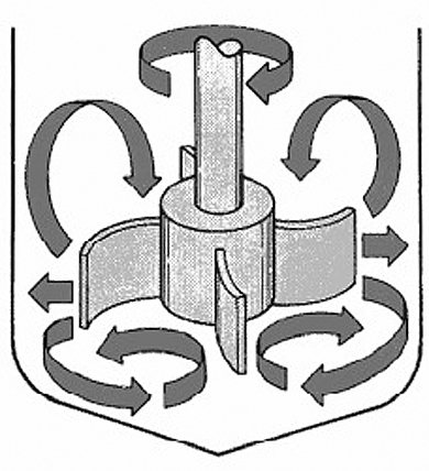
Curved blade impeller
Helical impellers
Helical impellars are used in applications involving highly viscous fluids, such as polymer melts and carmalized sugars. These designs incorporate outer (left and right) helical bands with minimal vessel wall clearance to achieve axial flow at low agitator speeds. In order to further enhance the axial flow patterns of non-Newtonian fluids, an additional inner helical flight with opposite handedness is attached to the impeller shaft (left). The inner flight produces downward pumping action, while the outer flight pumps in the upward direction.

Helical blade impeller
Anchor impeller
The anchor impeller design (left) is best suited for mixing of high viscosity fluids. The design produces radial flow at low speeds. These types of impellars often incorporate wipers that remove material from the vessel walls during agitation, which enhances heat transfer.

Anchor blade impeller
5.1 Heat transfer mechanism
In the simplest of terms, the discipline of heat transfer is concerned with only two things- temperature, and the flow of heat. Temperature represents the amount of thermal energy available, whereas heat flow represents the movement of thermal energy from place to place.
On a microscopic scale, thermal energy is related to the kinetic energy of molecules. The greater the material’s temperature, the greater is the thermal agitation of its constituent molecules (manifested both in linear motion and vibrational modes). It is natural for regions containing greater molecular kinetic energy to pass this energy to regions with less kinetic energy. Several material properties serve to modulate the heat transferred between two regions at differing temperatures. Examples include thermal conductivities, specific heats, material densities, fluid velocities, fluid viscosities, surface emissivities, and more. Taken together, these properties serve to make the solution of many heat transfer problems an involved process.
5.2 Heat exchangers
Heat exchangers play an important role in process industries. A heat exchanger is a device, which is used for transferring heat from one fluid to another through a separating wall. This can be classified according to the process of heat transfer, mechanical design and principal material of construction.
Classification of heat exchangers
The following types of heat exchangers are presently used in process industries:
- Double pipe heat exchangers
- Shell and tube heat exchangers
- Fixed tube sheet
- Outside packed floating head
- Internal floating head
- U-Tube type
- Re-boilers
Special types of exchangers
- Pipe coils
- Spiral heat exchanger
- Plate type exchanger
- Finned tube exchanger
- Graphite heat exchanger
- Air-cooled exchanger
5.2.1 Double pipe heat exchangers
Straight tubes, internal bolted floating head cover, removable tube bundle. No special provisions needed for expansion.
Applications
For heating or cooling chemical or hydrocarbon fluids, condensing air or gases.
Construction
Removable bundle, pull-through bolted internal floating head cover.

Double pipe exchanger
Advantages
- Allows for differential thermal expansion between the shell and tubes
- Bundle can be removed from shell for cleaning or repairing without removing the floating head cover
- Provides multi-tube pass arrangements
- Provides large bundle entrance area
- Excellent for handling flammable and/or toxic fluids
Limitations
- For a given set of conditions, it is the most costly of all the basic types of heat exchanger designs
- Less surface per given shell and tube size than C500
5.2.2 Shell and tube heat exchangers
They are intended for heating or cooling process fluids, they are for example suitable for closed circuit cooling of electrical equipment using dematerialized water and for cooling water soluble oil solutions in quenching tanks.
The shell side usually contains the process fluid and the tube side water from the town mains or a cooling tower, or an ethylene glycol solution from a chiller unit.
5.2.3 Fixed tube sheet
Generally the most economical type design; however, the shell side fluid must be non-fouling since the tube bundle cannot be removed. Either designing with can offset this sufficient fouling allowance or providing for chemical cleaning. Inside of tubes easily cleaned by removing heads.

Straight tube fixed bundle
5.2.4 Internal floating head
Straight tubes, internal bolted floating head cover, removable tube bundle. No special provisions needed for expansion.
Applications
For heating or cooling chemical or hydrocarbon fluids, condensing air or gases.
Construction
Removable bundle, pull-through bolted internal floating head cover.

Internal floating head
Advantages
- Allows for differential thermal expansion between the shell and tubes.
- Bundle can be removed from shell for cleaning or repairing without removing the floating head cover
- Provides multi-tube pass arrangements
- Provides large bundle entrance area
- Excellent for handling flammable and/or toxic fluids
Limitations
- For a given set of conditions, it is the most costly of all the basic types of heat exchanger designs
- Less surface per given shell and tube size than C500
5.2.5 Outside packed floating head
External packed floating head allows differential thermal expansion between shell and tubes. No packing is exposed to tube side fluid. Large entrance area enables easier maintenance of removable tube bundle. 1, 2, 4, or 6-pass models.

Outside floating head
Applications
For tube side circulation of corrosive liquids, high-fouling fluids, or gases and vapors.
Advantages
- Floating end allows for differential thermal expansion between the shell and tubes
- Shell side can be steam or mechanically cleaned
- Bundle can be easily repaired or replaced
- Less costly than full internal floating head-type construction
- Maximum surface per given shell and tube size for removable bundle designs
Limitations
- Shell side fluids limited to non-volatile and/or non-toxic fluids, i.e., lube oils, hydraulic oils
- Tube side arrangements limited to one or two pass
- Tubes expand as a group, not individually (as in U-tube unit); therefore, sudden shocking should be avoided
- Packing limits design pressure and temperature
5.2.6 U-tube type
Perhaps the most inexpensive type of heat exchanger because only one end of the tube bundle is restrained, the unit is free to expand and contract on severe temperature differential service. Most common use is for heating applications where steam is the heating medium. Tube side fluid must be non-fouling since inside tube surfaces cannot be manually cleaned but bundle is removable for cleaning of the outside tube surfaces.

U tube exchanger
5.2.7 Re-boilers
A re-boiler is used to turn the liquid leaving the bottom of a column into a vapor by transferring the heat of vaporization to the liquid.
Thermosyphon re-boilers
Thermosyphon re-boilers are generally heat exchangers used to provide vapor boil-up to a distillation column. They can be provided in either a vertical position with the boiling fluid in the tubes or in the horizontal position with the boiling fluid in the shell side. In normal operation, between 10% and 33% of the liquid entering the unit is boiled.

Thermosyphon re-boilers
Kettle re-boilers
Kettle re-boilers are used in services where 20% to 100% boil-up is required. The enlarged outer shell provides a separation between the boiling fluid and the exit nozzle reducing the amount of liquid entrainment in the exiting vapor stream. In cases where the amount of liquid entrainment must be minimal, a demister pad is provided inside the shell.

Kettle reboilers
5.2.8 Spiral heat exchanger
Spiral heat exchangers are custom built both in the thermal design & construction. They work efficiently for many applications in different industries. Spiral heat exchangers are designed to operate in a counter current mode and have low fouling.

Spiral exchangers
Advantages
- Optimal Use of Pressure Drop
- Differing Flow Rates in Each Channel
- High Heat Transfer Coefficients
- Minimum Fouling & Self Cleaning Effect
- Compactness of a Spiral
- Utilize the Smallest of Temperature Differences
Applications
- Chemical Industry
- Municipal/Sewage Treatment Plants
- Sterilization Plants
- Alcohol Plants
- Textile Mills
- Cellulose Industry
- Aluminum Plants
- Sugar
- Food Industry
5.2.9 Plate type exchanger
The plate heat exchanger, often called the plate-and-frame heat exchanger, consists of a frame, which holds heat transfer plates. A plate pack of corrugated metal plates with portholes for the media is aligned in a frame and compressed by tightening bolts. The plates form a series of channels for the two media. The channels are sealed by gaskets, which direct the fluid into alternate channels. The fluids normally flow in countercurrent flow, one in the odd number channels and one in the evenly numbered channels.
Plate heat exchangers are characterized by:
- Heat transfer efficiency up to five times that of other types of heat exchanger
- Compact dimensions which fit in a small space and are low weight
- Low investment and operating costs
- Flexible construction which can be extended or rearranged to meet new process conditions
- Low fouling as a result of turbulence created by the plate pattern
5.2.10 In-line plate heat exchangers
They have been designed as a low-cost alternative to our shell and tube types. They consist of numerous 316 stainless steel heat transfer plates, two outer covers and four connections copper vacuum-brazed together to form an integral unit.
Unlike other plate heat exchangers, they have a unique internal flow arrangement, which enables the inlet and outlet connections to be axially in line. This means that they can be installed directly in pipe work without any change of direction. Each fluid stream flows in series through alternate plates. As a consequence, the plate spacing is larger and internal velocities are higher than is normally the case with this type of heat exchanger, thus rendering them less prone to fouling.

Inline exchangers
5.2.11 Finned tube exchanger
Finned tube heat exchanger can be installed in a different two-phase flow media or low-density flow media heat exchanging process.

Fined tube exchangers
Typical applications include:
- Fluid Cooling and Heating Coils
- Compressor Intercoolers and After coolers
- Gas Turbine Inlet Air Chilling
- Exhaust Gas Waste Heat Recovery
- TEWAC Generator/Motor Coolers
- Transformer Oil Coolers
- Steam Distributing Heating Coils
- Food Dryer and Cooling Coils
- Furnace/Oven Heating and Cooling
5.2.12 Air-cooled exchanger
Air-cooled heat exchangers are generally used where a process system generates heat which must be removed, but for which there is no local use. A good example is the radiator in your car. The engine components must be cooled to keep them from overheating due to friction and the combustion process. The water/glycol coolant mixture carries the excess heat away. The car’s radiator to heat the interior may use a small amount of the excess heat. Most of the heat must be dissipated somehow. One of the simplest ways is to use the ambient air. Air-cooled heat exchangers (often simply called air-coolers) do not require any cooling water from a cooling tower. They are usually used when the outlet temperature is more than about 20 deg. F above the maximum expected ambient air temperature. They can be used with closer approach temperatures, but often become expensive compared to a combination of a cooling tower and a water-cooled exchanger.
Typically, an air-cooled exchanger for process use consists of a finned-tube bundle with rectangular box headers on both ends of the tubes. One or more fans provide cooling air. Usually, the air blows upwards through a horizontal tube bundle. The fans can be either forced or induced draft, depending on whether the air is pushed or pulled through the tube bundle. The space between the fan(s) and the tube bundle is enclosed by a plenum chamber, which directs the air. The whole assembly is usually mounted on legs or a pipe rack.
The fans are usually driven be electric motors through some type of speed reducer. The speed reducers are usually V-belts, HTD drives, or right angle gears. The fan drive assembly is supported by a steel mechanical drive support system. They usually include a vibration switch on each fan to automatically shut down a fan, which has become imbalanced for some reason.

Air-cooled exchangers
5.2.13 Graphite heat exchanger
Graphite heat exchanger is used wherever corrosive fluids or gases must be handled.
- Heating – corrosive fluids with steam, gases or hot fluids.
- Cooling – corrosive fluids with cold water, brine or other fluids.
- Condensing – vapors, gases – straight or reflux.
- Evaporating – boiling liquids in evaporation or distillation plants, etc.
- Reaction – including hydrolysis, polymerization or condensation reactions, where heat must be removed or supplied rapidly, during the reaction.

Graphite exchangers
5.3 Boilers
The boiler’s job is to apply heat to water to create steam. There are two approaches: fire tube and water tube.
5.3.1 Fire-tube boilers
Fire-tube boilers are generally similar to Scotch marine or locomotive boilers. In this type of boiler, the gases of combustion pass through tubes that are surrounded by water.
A fire-tube boiler was more common in the 1800s. It consists of a tank of water perforated with pipes. In a fire-tube boiler, the entire tank is under pressure, so if the tank bursts it creates a major explosion. The hot gases from a coal or wood fire run through the pipes to heat the water in the tank. Figure 5.13 illustrates a cutaway view of the fire-tube boiler.

Fire tube boiler
- Used primarily for space heating and smaller industrial processes
- Range in size from small steam outputs of 600,000 Btu/hr to very large steam output of 50 million Btu/hr
- Not suitable for high capacity/ high pressure steam generation; upper limit is typically 250psig
- Relatively low first cost
- Compact
- Easy to clean
- Ability to handle sudden and very big peak steam loads
- Not suitable for high capacity/ high pressure steam generation
5.3.2 Water tube boilers
Water-tube, natural-circulation boilers consist basically of a steam drum and a water drum connected by a bank of generating tubes. The two drums are also connected by a row of water tubes, which forms a water-cooled sidewall opposite the tube bank. The water-wall tubes pass beneath the refractory furnace floor before they enter the water drum. In natural-circulation boilers, several tubes of larger diameter, called down comers or water tubes, connect the steam and water drums. These tubes are positioned away from the flow of hot gases of combustion. Refractory is also used to protect these down comers from contact with the combustion gases.
The operating principle of a natural-circulation boiler is quite simple. It relies on the difference in density (weight) between the cooler (heavier) water in the water tubes (or down comers) and the hot, less dense (lighter) water in the steam-generating tubes. This is the force that causes the hot water and steam mixture to rise in the tubes in the generating bank, from the water drum to the steam drum, where the steam is separated from the water and rises to the top of the steam drum. The flow of water up the tubes of the steam-generating bank must be maintained; otherwise, the tubes would quickly melt.

Water tube boiler
A constant flow of water and steam up the tubes is required to carry away heat at the proper rate. If the flow from natural circulation is allowed to stop, such as when the water level in the steam drum falls below the openings of the bank of tubes for the water wall, the tubes of the generating bank will be severely damaged and the boiler will need major repairs. (Replacing boiler tubes is an expensive operation.)
5.3.3 Tubeless boilers
These high quality systems are ideal for small space installations where volume, simplicity and reliability are critical. All units are test-fired at the factory before shipping, ensuring top performance upon installation.

Tubeless boiler
5.3.4 Circulating fluid bed (CFB) boiler
The CFB boiler is designed for high reliability and availability with low maintenance, while complying with stringent emissions regulations.
In a circulating fluidized-bed boiler, a portion of air is introduced through the bottom of the bed. The bed material normally consists of fuel, limestone and ash. Water-cooled membrane walls with specially designed air nozzles support the bottom of the bed, which distributes the air uniformly. The fuel and limestone (for sulfur capture) are fed into the lower bed. In the presence of fluidizing air, the fuel and limestone quickly and uniformly mix under the turbulent environment and behave like a fluid. Carbon particles in the fuel are exposed to the combustion air. The balance of combustion air is introduced at the top of the lower, dense bed. This staged combustion limits the formation of nitrogen oxides (NOx).
The bed fluidizing air velocity is greater than the terminal velocity of most of the particles in the bed and thus fluidizing air elutriates the particles through the combustion chamber to the U-beam separators at the furnace exit. The captured solids, including any unburned carbon and unutilized carbon oxide (CaO), are re-injected directly back into the combustion chamber without passing through an external re-circulation. This internal solids circulation provides longer residence time for fuel and limestone, resulting in good combustion and improved sulfur capture.
5.3.5 AFBC boilers
One of these advanced technologies is Atmospheric Fluidized Bed Combustion (AFBC), which promises to provide a viable alternative to conventional coal fired boilers for utility and industrial application.
The principal features are:
- Drum Natural circulation design
- Baffle less boiler bank (Cross flow)
- Bottom Supported boiler block
- Machine welded membrane wall – gas Tight Furnace
- Underbed fuel feed system using drag chain feeders for smooth flow of high moisture fuel to feed lines
- Fuel feeding lines of higher thickness for longer life
- Hot air for feeding fuel inside combustion for smooth flow fuel in feed lines
- No bends on the fuel transport lines – preventing choking of fuel
- Distributor plate 16-mm. thickness Carbon Steel
- High-density rounds studs welded on inbed surfaces to minimize erosion
5.3.6 Solid fuel fired boiler
The steam boilers fired with wood-waste (sawdust, bark, chopped wood) are designed to raise technological steam in thermal power stations.
They are natural circulation flue boilers, with the heat exchange surfaces arranged on three gas paths, and negative pressure in the furnace.

Solid fuel boiler
5.3.7 Thermal oil heating boilers
The heating boilers using thermal oil (mineral oil) are complex units, forming parts of the “Thermal oil heating plants”. They are designed to provide for an outlet temperature ranging between 290-300 °C, at a low pressure (6 bar).
The boilers are used in any application required a temperature of max. 290-300 °C for the heat carrier.

Thermal boiler
5.4 Evaporators
Evaporation refers to the process of heating liquid to the boiling point to remove water as vapor. Because milk is heat sensitive, heat damage can be minimized by evaporation under vacuum to reduce the boiling point.
The basic components of this process consist of:
- Heat-exchanger
- Vacuum
- Vapor separator
- Condenser
The heat exchanger is enclosed in a large chamber and transfers heat from the heating medium, usually low-pressure steam, to the product usually via indirect contact surfaces. The vacuum keeps the product temperature low and the difference in temperatures high. The vapor separator removes entrained solids from the vapors, channeling solids back to the heat exchanger and the vapors out to the condenser. It is sometimes a part of the actual heat exchanger, especially in older vacuum pans, but more likely a separate unit in newer installations. The condenser condenses the vapors from inside the heat exchanger and may act as the vacuum source.
The driving force for heat transfer is the difference in temperature between the steam in the coils and the product in the pan. The steam is produced in large boilers, generally tube and chest heat exchangers. The steam temperature is a function of the steam pressure. Water boils at 100° C at 1 atm., but at other pressures the boiling point changes. At its boiling point, the steam condenses in the coils and gives up its latent heat. If the steam temperature is too high, burn-on/fouling increases so there are limits to how high steam temperatures can go. The product is also at its boiling point. The boiling point can be elevated with an increase in solute concentration. This boiling point elevation works on the same principles as freezing point depression.

Principle of operation
Evaporator designs
Types of single effect evaporators:
- Batch Pan
- Rising film
- Falling film
- Plate evaporators
- Scraped surface
5.4.1 Batch pan
These evaporators are the simplest and oldest. They consist of spherical shaped, steam jacketed vessels. The heat transfer per unit volume is small requiring long residence times. The heating is due only to natural convection; therefore, the heat transfer characteristics are poor. Batch plants are of historical significance; modern evaporation plants are far-removed from this basic idea. The vapors are a tremendous source of low-pressure steam and must be reused.
They are currently used in making jams and jellies but mostly outdated by more efficient means of evaporation. A batch pan evaporator is one of the oldest methods of concentrating.

Batch pan evaporator
5.4.2 Rising film
They consist of a heat exchanger isolated from the vapor separator. The heat exchanger, or calandria, consists of 10 to 15 meter long tubes in a tube chest, which is heated with steam. The liquid rises by percolation from the vapors formed near the bottom of the heating tubes. The thin liquid film moves rapidly upwards. The product may be recycled if necessary to arrive at the desired final concentration. This development of this type of modern evaporator has given way to the falling film evaporator.
Dating back to the early 1900s, this equipment uses a vertical tube with steam condensing on its outside surface. Liquid on the inside of the tube is brought to a boil, with the vapor generated forming a core in the center of the tube. As the fluid moves up the tube, more vapors are formed resulting in a higher central core velocity those forces the remaining liquid to the tube wall.

Rising film evaporator
5.4.3 Falling film
These types of evaporators are the most widely used in the food industry. They are similar in components to the rising film type except that the thin liquid film moves downward under gravity in the tubes. A uniform film distribution at the feed inlet is much more difficult to obtain. This is the reason why this development came slowly and it is only within the last decade that falling film has superceded all other designs. Specially designed nozzles or spray distributors at the feed inlet permit it to handle more viscous products. The residence time is 20-30 sec. as opposed to 3-4 min. in the rising film type. The vapor separator is at the bottom which decreases the product hold-up during shut down. The tubes are 8-12 meters long and 30-50 mm in diameter.

Falling film evaporator
5.4.4 Falling film tubular
Similar to the rising film unit, this unit has several advantages. First, because the vapor is working in the same direction as gravity, these units are more efficient. Second, to establish a well-developed film, the rising film unit requires a driving film force, typically a temperature difference of at least 25 degrees across the heating surface whereas the falling film evaporator is not limited by this permitting many more multiple effect stages of evaporation. Therefore, with this technology, it is feasible to have as many as ten effects in a process.
5.4.5 Forced circulation
The forced circulation evaporator was developed for processing liquors, which are susceptible to scaling or crystallizing. Liquid is circulated at a high rate through the heat exchanger, boiling being prevented within the unit by virtue of a hydrostatic head maintained above the top tube plate. As the liquid enters the separator where the absolute pressure is slightly less than in the tube bundle, the liquid flashes to form a vapor.
The main applications are in the concentration of inversely soluble materials, crystallizing duties and in the concentration of thermally degradable materials, which result in the deposition of solids.

Forced circulation evaporator
5.4.6 Plate equivalents of tubular evaporators
Plate type evaporators were initially developed by APV in 1957 to provide an alternative to tubular systems to meet the growing challenges of the process industries. The plate evaporator offers full accessibility to the heat transfer surface. It also provides flexible capacity merely by adding more plate units, shorter product residence time resulting in a quality concentrate, a more compact design with low headroom requirements and low installation cost.

Tubular evaporator
5.4.7 Scrapped surface thin film evaporators
They are designed for evaporation of highly viscous and sticky products, which cannot be otherwise evaporated. This type of evaporators have been specially designed to provide high degree of agitation, effecting heat transfer as well as scrapping the walls of the evaporator to prevent deposition and subsequent charring of the product.
In circumstances in which a scale is formed the tubes of the calandria can be scraped to remove the scale. Such evaporators are called Scrapped surface tube evaporators. Inside the tubes are rotating devices, which scrape off any scale formed with spring-loaded blades. These scraping devices can be used in long tube or short tube evaporators, however, particularly in long tube evaporators there can be problems of poor liquid distribution. The scale that is removed must be separated from the product later in the process. Other types of evaporator are often more efficient for use with liquids that form scale.
5.4.8 Vertical agitated thin film evaporators (ATFE)
They contain a rotor designed to produce and agitate a thin film between the rotor and the heated wall of the evaporator. The agitation of the film on the heated surface promotes heat transfer and maintains precipitated or crystallized solids in a manageable suspension without fouling the heat transfer surface. This capability makes ATFEs particularly suited for volume reduction of radioactive wastes that contain suspended solids. The tests were conducted with surrogates that contained no radionuclides. The results of the tests indicated that a variety of products could be produced with the ATFE. It was possible to vary the consistency from a highly concentrated liquid to a completely dry powder. Volume reductions ranged from ~20 to 68% and decontamination factors in the range of 10,000 to 100,000 were achieved.

ATFE
5.4.9 Multiple effect evaporators
Two or more evaporator units can be run in sequence to produce a multiple effect evaporators. Each effect would consist a heat transfer surface, a vapor separator, as well as a vacuum source and a condenser. The vapors from the preceding effect are used as the heat source in the next effect.
There are two advantages to multiple effect evaporators:
- Economy – they evaporate more water per kg steam by re-using vapors as heat sources in subsequent effects
- Improve heat transfer – due to the viscous effects of the products as they become more concentrated
Each effect operates at a lower pressure and temperature than the effect preceding it so as to maintain a temperature difference and continue the evaporation procedure. The vapors are removed from the preceding effect at the boiling temperature of the product at that effect so that no temperature difference would exist if the vacuum were not increased. The operating costs of evaporation are relative to the number of effects and the temperature at which they operate. The boiling milk creates vapors, which can be recompressed for high steam economy. This can be done by adding energy to the vapor in the form of a steam jet, thermo compression or by a mechanical compressor, mechanical vapor recompression.

Multiple effect evaporators
5.4.10 Thermo compression (TC) evaporator
Involves the use of a steam-jet booster to recompress part of the exit vapors from the first effect. Through recompression, the pressure and temperature of the vapors are increased. As the vapors exit from the first effect, they are mixed with very high-pressure steam. The steam entering the first effect calandria is at slightly less pressure than the supply steam. There are usually more vapors from the first effect than the second effect can use. Usually only the first effect is coupled with multiple effect evaporators.

Double-effect thermal recompression evaporator
To reduce energy consumption, water vapor from an evaporator is entrained and compressed with high-pressure steam in a thermo compressor so it can be condensed in the evaporator heat exchanger. The resultant pressure is intermediate to that of the motive steam and the water vapor. A thermo compressor is similar to a steam-jet air ejector used to maintain vacuum in an evaporator.
Only a portion of the vapor from an evaporator can be compressed in a thermo compressor with the remainder condensed in the next-effect heat exchanger or a condenser. A thermo compressor is normally used on a single-effect evaporator or on the first effect of a double- or triple-effect evaporator to reduce energy consumption. As with mechanical recompression, thermal recompression is more applicable to low boiling-point rise liquids and low to moderate Delta-T’s in the heat exchanger to minimize the compression ratio.
5.4.11 Mechanical vapor recompression (MVR)
Whereas only part of the vapor is recompressed using TC, all the vapor is recompressed in an MVR evaporator. Radial compressors or simple fans using electrical energy mechanically compress vapors.
There are several variations; in single effect, all the vapors are recompressed therefore no condensing water is needed; in multiple effect, can have MVR on first effect, followed by two or more traditional effects; or can recompress vapors from all effects

MVR cycle
Increasing energy costs have justified the increased use of mechanical recompression evaporators. The principle is simple. Vapor from an evaporator is compressed (with a positive-displacement, centrifugal or axial-flow compressor) to a higher pressure so that it can be condensed in the evaporator heat exchanger. Various combinations are possible, including single-effect recompression, multiple-effect recompression, multiple-stage recompression, and single-effect recompression combined with a multiple-effect evaporator.
A simplified flow sheet of a single-effect recompression evaporator illustrates why mechanical recompression is energy efficient
Mechanical recompression is not limited to single-effect evaporation. It is sometimes economical to compress vapor from the last effect of a double- or triple-effect evaporator so that the vapor can be condensed in the first-effect heat exchanger.
6.1 Mass transfer phenomena
A group of unit operations for separating the components of mixtures is based on the transfer of material from one homogenous phase to another. The driving force for transfer is a concentration difference or a concentration gradient; much like a temperature difference or a temperature gradient provides the driving force for heat transfer.
These methods, covered by the term mass-transfer operations, include such techniques as indicated below:
- Distillation
- Leaching
- Gas absorption
- Dehumidification
- Liquid extraction
- Drying
6.2 Distillation
It is a process in which, a liquid or vapor mixture of two or more substances is separated into its component fractions of desired purity, by the application and removal of heat.
Distillation is based on the fact that the vapor of a boiling mixture will be richer in the components that have lower boiling points. Therefore, when this vapor is cooled and condensed, the condensate will contain components that are more volatile. At the same time, the original mixture will contain more of the less volatile material. Distillation columns are designed to achieve this separation efficiently.
The important aspects that seem to be missed from the manufacturing point of view are that:
- Distillation is the most common separation technique
- It consumes enormous amounts of energy, both in terms of cooling and heating requirements
- It can contribute to more than 50% of plant operating costs
The best way to reduce the operating costs of existing units is to improve their efficiency and operation via process optimization and control.
6.2.1 Main components of distillation unit
A typical distillation contains several major components:
- A vertical shell where the separation of liquid components is carried out
- Column internals such as trays/plates and/or packing which are used to enhance component separations
- A re-boiler to provide the necessary vaporization for the distillation process
- A condenser to cool and condense the vapor leaving the top of the column
- A reflux drum to hold the condensed vapor from the top of the column so that liquid (reflux) can be recycled back to the column
The vertical shell houses the column internals and together with the condenser and re-boiler, constitute a distillation column. A schematic of a typical distillation unit with a single feed and two product streams is shown below:

Typical distillation unit
6.2.2 Basic operation and terminology
The liquid mixture that is to be processed is known as the feed and this is introduced usually somewhere near the middle of the column to a tray known as the feed tray. The feed tray divides the column into a top (enriching or rectification) section and a bottom (stripping) section. The feed flows down the column where it is collected at the bottom in the re-boiler.
Heat is supplied to the re-boiler to generate vapor. The source of heat input can be any suitable fluid, although in most chemical plants this is normally steam. In refineries, the heating source may be the output streams of other columns. The vapor raised in the re-boiler is re-introduced into the unit at the bottom of the column. The liquid removed from the re-boiler is known as the bottoms product or simply, bottoms.

Operation philosophy

Vapor section
The vapor moves up the column, and as it exits the top of the unit, it is cooled by a condenser. The condensed liquid is stored in a holding vessel known as the reflux drum. Some of this liquid is recycled back to the top of the column and this is called the reflux. The condensed liquid that is removed from the system is known as the distillate or top product.
Thus, there are internal flows of vapor and liquid within the column as well as external flows of feeds and product streams, into and out of the column
6.3 Types of distillation columns
There are many types of distillation columns, each designed to perform specific types of separations, and each design differs in terms of complexity.
6.3.1 Batch columns
In batch operation, the feed to the column is introduced batch-wise. That is, the column is charged with a ‘batch’ and then the distillation process is carried out. When the desired task is achieved, a next batch of feed is introduced and continuous
6.3.2 Continuous columns
In contrast, continuous columns process a continuous feed stream. No interruptions occur unless there is a problem with the column or surrounding process units. They are capable of handling high throughputs and are the most common of the two types.
Continuous columns can be further classified according to:
Nature of the feed that they are processing:
- Binary column – feed contains only two components
- Multi-component column – feed contains more than two components
Number of product streams they have:
- Multi-product column – this column has more than two product streams
Where the extra feed exits when it is used to help with the separation:
- Extractive distillation – where the extra feed appears in the bottom product stream
- Azeotropic distillation – where the extra feed appears at the top product stream
Type of column internals:
- Tray column – where trays of various designs are used to hold up the liquid to provide better contact between vapor and liquid, hence better separation
- Packed column – where instead of trays, ‘packings’ are used to enhance contact between vapor and liquid
6.4 Column internals
A tray essentially acts as a mini-column, each accomplishing a fraction of the separation task. Trays are designed to maximize vapor-liquid contact by considering the liquid distribution and vapor distribution on the tray. This is because better vapor-liquid contact means better separation at each tray, translating to better column performance. Less trays will be required to achieve the same degree of separation. Attendant benefits include less energy usage and lower construction costs. There is a clear trend to improve separations by supplementing the use of trays by additions of packing.
6.4.1 Conventional trays
The terms ‘trays’ and ‘plates’ are used interchangeably. There are many types of tray designs, but the most common ones are:
Bubble cap trays
A bubble cap tray has riser or chimney fitted over each hole, and a cap that covers the riser. The cap is mounted so that there is a space between riser and cap to allow the passage of vapor. Vapor rises through the chimney and is directed downward by the cap, discharging through slots in the cap, and finally bubbling through the liquid on the tray.
The conventional bubble cap tray is well proven in applications having:
- Very large loading ranges
- Very low liquid loadings
- Very low gas loadings
- Constant liquid holdup
- Low leakage rates

Bubble cap tray
Valve trays
In valve trays, perforations are covered by lift able caps. Vapor flows lift the caps, thus self-creating a flow area for the passage of vapor. The lifting cap directs the vapor to flow horizontally into the liquid, thus providing better mixing than is possible in sieve trays.

Valve tray
Due to the wide operating range they can handle, valve trays are now the most commonly used type of mass transfer trays. The valve tray differentiates itself from other trays by its ability to handle high capacities at excellent mass transfer efficiencies over a wide operating range. Depending on the application, a specific type of valve is selected.
Sieve trays
Sieve trays are simply metal plates with holes in them. Vapor passes straight upward through the liquid on the plate. The arrangement, number and size of the holes are design parameters.

Sieve tray
The sieve trays are very cost-competitive mass transfer trays. The operating range of these sieve-perforated trays is less than that of valve trays.
Because of their efficiency, wide operating range, ease of maintenance and cost factors, sieve and valve trays have replaced the once highly thought of bubble cap trays in many applications.
Chimney trays
A purpose designed Chimney Tray must be installed to function as a collector device either for feeding to a liquid distributor (particularly flashing feeds) or for a liquid draws off. A leaky chimney tray will result in liquid by-passing the distributor causing maldistribution in the packed bed. To avoid this, all chimney trays, which are used to collect liquid to feed a liquid distributor, should have all joints seal welded after installation.
When installed below the bottom packed bed, Chimney Trays perform a useful function as a vapor distributor. This is especially important where high vapor rates are encountered due to the low-pressure drop across most packed beds.

Chimney tray
6.4.2 High performance trays
These technologically advanced trays employ innovative down-comer designs and active area enhancements to provide minimal pressure drop, optimum mass transfer efficiency, and high capacity.

High performance tray
6.4.3 Tower packings
Packings are passive devices that are designed to increase the interfacial area for vapor-liquid contact. These strangely shaped pieces are supposed to impart good vapor-liquid contact when a particular type is placed together in numbers, without causing excessive pressure-drop across a packed section. This is important because a high-pressure drop would mean that more energy is required to drive the vapor up the distillation column.
Random packings
Random packings are an inexpensive packing alternative to increase a tower’s capacity and efficiency
Metal packings
Metal packings are lighter and resist breakage better than ceramic packings, making metal the choice for deep beds. Metal also lends itself to packing geometries that yield higher efficiencies than ceramic or plastic packing shapes. Compared to most standard plastic packings, metal packings withstand higher temperatures and provide better wetting ability.
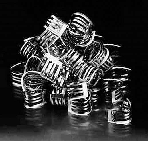
Metallic packing
High-performance random tower packing
- Provides greater capacity and efficiency than fractionation trays and other random packings
- Exhibits roughly 40% lower pressure drop than equal-sized pall rings
- Minimizes liquid residence time through low liquid holdup
- This type of packing is ideal in a wide range of mass transfer services. It is used extensively in distillation towers from deep vacuum towers where its low pressure drop is crucial, to high-pressure towers where its capacity easily surpasses that of trays

Random tower packing
High-strength pall ring & raschig rings
- Physical strength without thickness and weight
- Economically priced
- Our high-strength pall ring combines flared ends with a latch that holds the ring seams together for uniform closure and added strength for use in beds up to 50 feet (15m). The high-strength pall ring is currently available in a 2-in. (50mm) size in a broad range of metals

Rasching ring
6.4.4 Packed tower internals
The proper selection and design of packed tower distributors, collectors, supports, and other column internals are essential for optimum packing performance.
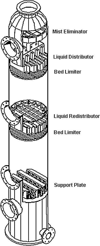
Packed tower internals
Support plates
They provide structural support for packing. A well-designed packing support plate provides structural support for the tower packing. Weight loads associated with installation, liquid holdup during operation and the potential for scaling or buildup of solids enter into the design considerations. The support plate must minimize resistance to the flows of rising vapor and down coming liquid. Additionally the support plate must be easy to install.

Support plates
Liquid distributors
Proper liquid distribution represents one of the most important aspects of packed tower design. For critical applications in large towers, we recommend the trough distributor.

Liquid distributors
Liquid re-distributors
Optimum tower performance depends upon uniform liquid distribution though multiple packed beds. Re-distributors accomplish this task by accumulating the liquid leaving an upper bed and distributing it in a uniform patter over a lower bed.
Collecting trays are required if more than one liquid is used in a multiple bed packed tower. The collecting tray collects and removes liquid from the tower while permitting vapor to move upward though the successive packed bed.

Liquid Re-distributors
Collecting trays
Optimum tower performance depends upon uniform liquid distribution though multiple packed beds. Re-distributors accomplish this task by accumulating the liquid leaving an upper bed and distributing it in a uniform patter over a lower bed.
Collecting trays are required if more than one liquid is used in a multiple bed packed tower. The collecting tray collects and removes liquid from the tower while permitting vapor to move upward though the successive packed bed.

Collecting trays
Bed limiters
Bed limiters hold packings in their proper location. The gas velocity and the packing material determine whether a given tower requires a bed limiter. High gas velocities can lift the packing, dislocating it into the liquid distributor or beyond. This adversely impacts the performance of the liquid distributor and the efficiency of the tower.

Bed limiters
Mist eliminators
Carry over of liquid particulate matter by gas or vapor is generally termed as ‘Entrainment’, which is commonly encountered in Gas-Liquid separations
Mist eliminators are a highly efficient, low cost means of removing entrained liquid droplets from gas and vapor streams.

Mist eliminators
6.4.5 Structured packing
In general, the deciding issue for structured packing is more a question of vapor density and liquid density rather than system pressure.
Three criteria control the selection of structured packing:
- Liquid load
- Vapor density
- Liquid-to-vapor density ratio
For distillation systems, the vapor density and the liquid-to-vapor density ratio are strongly linked. The lower the vapor density, the better-structured packing performs compared to other devices. The higher the vapor density, the better trays or random packing performs compared to structured packing.

Structured packing
6.5 Types of distillation
6.5.1 Fractional distillation
If a portion of the distillate is returned from the condenser and made to drip down through a long column onto a series of plates, and if the vapor rises on its way to the condenser is made to bubble through this liquid at each plate, the vapor and liquid will interact so that some of the water in the vapor condenses and some of the alcohol in the liquid vaporizes. The interaction at each plate is thus equivalent to a re-distillation, and by building a column with a sufficient number of plates, 95 percent alcohol can be obtained in a single operation. Moreover, by feeding the original 10 percent alcohol solution gradually at a point in the middle of the column, virtually all the alcohol may be stripped from the water as it descends to the lowest plate, so that no alcohol need be wasted.
This process, known as rectification, fractionation, or fractional distillation, is common in industrial usage, not only for simple mixtures of two components (such as alcohol and water in fermentation products, or oxygen and nitrogen in liquid air) but also for highly complex mixtures such as those found in coal tar and petroleum.

Fractionating column
The only disadvantage of fractional distillation is that a large fraction (as much as one-half) of the condensed distillate must be refluxed, or returned to the top of the tower and eventually boiled again, and more heat must therefore be supplied. On the other hand, the continuous operation made possible by fractionation allows great heating economies, because the outgoing distillate may be used to preheat the incoming feed.
When the mixture consists of many components, they are drawn off at different points along the tower. Industrial distillation towers for petroleum often have over 100 plates, with as many as ten different fractions being drawn off at suitable points. Towers with more than 500 plates have been used for the separation of isotopes by distillation.
6.5.2 Steam distillation
If two insoluble liquids are heated, each is unaffected by the presence of the other (as long as they are agitated so that the lighter liquid does not form an impenetrable layer over the heavier), and vaporizes to an extent determined only by its own volatility. Such a mixture, therefore, always boils at a temperature lower than that of either constituent; and the percentage of each constituent in the vapor depends only on its vapor pressure at this temperature. This principle may be applied to substances that would be damaged by overheating if distilled in the usual fashion.

Steam distillation unit
6.5.3 Vacuum distillation
Another method of distilling substances at temperatures below their normal boiling points is to partially evacuate the still. Thus, aniline may be distilled at 100° C (212° F) by removing 93 percent of the air from the still. This method is as effective as steam distillation, but somewhat more expensive. The greater the degree of vacuum, the lower is the distillation temperature. If the distillation is carried on in a practically perfect vacuum, the process is called molecular distillation. This process is regularly used industrially for the purification of vitamins and certain other unstable products. The substance is placed on a plate in an evacuated space and heated. The condenser is a cold plate, placed as close to the first as possible. Most of the material passes across the space between the two plates, and therefore very little is lost.
The VDU (Vacuum Distillation Unit) takes the residuum from the ADU (Atmospheric Distillation Unit) and separates the heavier products such as vacuum gas oil, vacuum distillate, slop wax, and residue.
6.5.4 Centrifugal molecular distillation
If a tall column of mixed gases is sealed and placed upright, a partial separation of the gases takes place because of gravity. In a high-speed centrifuge or an instrument called a vortex, the forces separating the lighter and heavier components from each other are thousands of times greater than gravity, making the separation more efficient. For example, separation of gaseous uranium hex fluoride, UF6, into molecules containing two different uranium isotopes, uranium-235 and uranium-238, may be effected by means of centrifugal molecular distillation.
6.5.5 Destructive distillation
If a substance is heated to a high temperature and decomposed into several valuable products, and these products are separated by fractionation in the same operation, the process is called destructive distillation. The important applications of this process are the destructive distillation of coal for coke, tar, gas, and ammonia, and the destructive distillation of wood for charcoal, acetic acid, acetone, and wood alcohol. The latter process has been largely displaced by synthetic processes for making the various by-products. The cracking of petroleum is similar to destructive distillation.
6.5.6 Flash distillation
Flash Distillation is a process by which a liquid-liquid mixture is separated by vaporizing one of the components in a tank (‘flash drum’). After leaving the tank, the vaporized component is then condensed, leaving two separate components. The components of the liquid-liquid mixture are separated based on volatility
The liquid-liquid mixture (‘the feed stream’) is pumped through a heater where the temperature is increased. The pressure is then reduced as the feed flows through a valve and into the flash drum. The reduced pressure in conjunction with the increased temperature causes a vaporization of the more volatile component. In the flash drum, the two phases are given a large enough volume to separate. The liquid and vapor phases flow out of the bottom and top, respectively.
Flash distillation should be used when separating two liquid components with significant differences in boiling points. The amount of separation in flash distillation is limited, which makes it a poor choice when a high purity is desired. The mechanism of separation for flash distillation is heat, so consideration should be taken when components are heat sensitive. This process occur when the product enter into a vessel.
Figure 6.22 shows the elements of a flash-distillation plant. Feed is pumped by pump through a heater, and the pressure is reduced through valve. An intimate mixture of vapor and liquid enters the vapor separator, in which sufficient time is allowed for the vapor and liquid portions to separate. Because of the intimacy of contact of liquid and vapor before separation, the separated streams are in equilibrium.

Flash distillation unit
Examples and applications
- Petroleum Processing – Flash Distillation is used to separate petroleum in a process called ‘cracking’. The products produced include: gasoline, kerosene, lubricating oils, asphalt, etc
- Alcohol Production – Flash Distillation is used to separate the ethanol (vapor phase) from the water (liquid phase) in order to form a more concentrated product
- Desalination of Water – Flash Distillation is used to purify salt water by boiling off pure water, leaving salt behind in the remaining water
- Perfume Spray – Flash Distillation is used to extract the essential oils of flowers and cedar to make perfume
Multi-stage flash distillation
Multi-Stage Flash (MSF) is the most commonly used process for seawater desalination. A MSF facility is typically located so that it uses steam from a nearby electricity generation facility. Seawater is heated in a ‘brine heater’ and proceeds to another receptacle, called a stage, where it immediately boils (flash) due in part to the ambient pressure. The steam yielded is the condensed on heat exchanger tubes that in turn heat up the incoming water, thereby decreasing the amount of thermal energy needed to heat the Feed water.
It is an advantage to perform flash-distillation in several steps. This is called multi-stage flash evaporation or MSF for short. This is where the preheated liquid passes through a series of stages or chambers with each successive stage at a lower vapor pressure so some of the liquid will flash at each stage.
Flash distillation begins when the salt water enters a bundle of tubes which are located in the vapor space of the preheat chamber. The water then flows into a heater consisting of a bundle of tubes, which are heated externally by steam. Here, the water is heated to 100 degrees C, but it does not boil because the pressure is above 1 atm. The hot seawater then enters a flash chamber, which is kept under reduced pressure. The vapors, which are flashed off, are then condensed on the tubes carrying the incoming flow of cold seawater. The distillate and the remaining salt water are then restored to atmospheric pressure by pumps. Condensing the water by heat exchange with the incoming flow in one of the economical advantages of this process.
The multiple stage evaporators is able to produce more distillate per unit of heating steam because the flashing occurs in more than one stage since the flashed vapors are used to heat the incoming water.

Multiple flash units
6.5.7 Osmosis distillation
Osmosis denotes the movement of water down a concentration gradient. Water moves from an area of high concentration to an area of lower concentration. Rather than using concentration gradients as a driving force, osmotic distillation uses the differences in vapor pressures of the contacting liquid phases. This allows actual separation of water from other components without the other components ‘following’ the water as it moves.
This is particularly useful in concentrating food and pharmaceutical products that are sensitive to elevated temperatures. A liquid phase with one or more volatile components is separated from a salt solution by a non-wetting polymer membrane. The membrane is typically made of non-polar polymers such as polyethylene, polypropylene, or PTFE.
This membrane functions as a vapor barrier between the liquid phases. The salt solution is usually composed of sodium or calcium chloride. Figure 6.24 shows the interface arrangement used in osmotic distillation.

Interface arrangement of osmotic distillation
Mechanism
Water moves across the Osmotic Distillation (OD) membrane by evaporating, diffusing through the pores, and condensing on the other side of the pores. The liquid is prohibited from entering the pores by membrane design. The membrane is designed such that the liquids cannot exceed the capillary forces required to enter the pores. Design factors include surface tension, contact angle, capillary pressure, and pore radius. The heat of vaporization is supplied by conduction or convection from the upstream liquid through the membrane. The temperature gradient across the membrane is typically less than 2 0C making the process nearly isothermal.
Figure below shows a typical setup used in osmotic distillation.

Typical setup used in osmotic distillation
Osmotic distillation provides a means of purifying heat sensitive substances including pharmaceuticals and biological products.
6.6 Sublimation
If a solid substance is distilled, passing directly into the vapor phase and back into the solid state without a liquid being formed at any time, the process is called sublimation. Sublimation does not differ from distillation in any important respect, except that special care must be taken to prevent the solid from clogging the apparatus. Rectification of such materials is impossible. Iodine is purified by sublimation.
6.7 Leaching
Removal of materials by dissolving them away from solids is called leaching. Leaching has been used to separate metals from their ores and to extract sugar from sugar beets. Environmental engineers have become concerned with leaching more recently because of the multitude of dumps and landfills that contain hazardous and toxic wastes. Sometimes the natural breakdown of a toxic chemical results in another chemical that is even more toxic. Rain that passes through these materials enters ground water, lakes, streams, wells, ponds, and the like.
Although many toxic materials have low solubility in water, the concentrations that are deemed hazardous are also very low. Furthermore, many toxic compounds are accumulated by living cells and can be more concentrated inside than outside a cell. This is why long-term exposure is a serious problem; encountering a low concentration of a toxic material a few times may not be dangerous, but having it in your drinking water day after day and year after year can be deadly.
For single stage leaching, two steps are involved:
- Contact of solid and solvent for transfer of solute to solvent
- Separation of resulting solution from the residual solid
The EXTRACT is the solvent phase.
The RAFFINATE is the solid material and its adhering solution.
The solute in the raffinate is in both dissolved and undissolved forms.

Terminology
The main theory of leaching neglects mechanisms for holding the material on the solid. Although adsorption and ion exchange can bind materials tightly to solids, we will simplify the analysis and consider only dissolving a soluble constituent away from an insoluble solid. An example is removing salt from sand by extraction with water.
Countercurrent stage wise processes are frequently used in industrial leaching because they can deliver the highest possible concentration in the extract and can minimize the amount of solvent needed. The solvent phase becomes concentrated as it contacts in a stage wise fashion the increasingly solute-rich solid. The raffinate becomes less concentrated in soluble material as it moves toward the fresh solvent stage.

Leaching stages
6.7.1 Heap leaching
Heap leaching is a countercurrent process where the solid is in a stationary heap and the solvent percolates through the solid. An example is a dump or landfill. This leaching is essentially countercurrent. In industrial leaching, solvent and solid are mixed, allowed to approach equilibrium, and the two phases are separated. Liquid and solids move counter currently to the adjacent stages. The solvent phase, called the extract, becomes more concentrated as it contacts in stage wise fashion the increasingly solute-rich solid. The raffinate becomes less concentrated in soluble material as it moves toward the fresh solvent phase.

Heap leaching
Heap leaching is also used in recovering metals from their ores. Bacterial leaching is first used to oxidize sulphide minerals. Cyanide solution is then used to leach the metals from the mineral heap.

Metal recovery through Heap Leaching
6.7.2 Leaching for remediation
Leaching has potential for clean up of toxic waste sites, but there must be no dispersal of the contaminants to adjacent areas. If the toxic material is soluble in water, it may already be dispersed by the percolation of rainwater or by flow of groundwater.
The penetration of wastes down into the soil has been modeled by several groups. A representative paper by Janssen, et al., (1990) considers the migration of radioisotopes deposited on soil by fallout from a nuclear accident.
Movement depends on convection with the solvent, diffusion, and exchange with the soil solids. This is much more complicated than batch or countercurrent leaching where we neglected any binding of the solute because the equilibria are complex and the motion is in three dimensions. Problems of this type require considering many elements that interact. The term for this approach is finite element analysis, and linear algebra with matrices aids the solutions.
If contaminated soil were flushed by pumping water through it, the pumped water under pressure would escape to the surroundings. This is unacceptable because the toxic wastes would be diluted to make treatment more difficult and dispersed to make collection more costly. A well to withdraw contaminated water should be in the region of highest concentration of contaminant. The following sketch shows a pumping scheme that might be acceptable for leaching with water pumped at the periphery to create higher pressure to prevent flow out of the site. The leachate is treated (a bioprocess is shown in this figure) and recycled. The above-ground treatment is tricky because the concentration of toxic material will usually be low. Both chemical and biological processes have troubles in dealing with dilute streams.
Toxic and hazardous wastes are often organic chemicals with poor water solubility. The most efficient way to extract them from soil would be to use organic solvents. However, adding solvents to soil would make the problem worse even if the solvents were not toxic. The expense would be unreasonable, and organics would represent very high BOD. One solvent that has been proposed is supercritical carbon dioxide in which many organic compounds are highly soluble. Lost solvent would merely escape to the air. The drawback is that the temperature and pressure to keep the carbon dioxide in its supercritical state would be a severe engineering challenge. There are only a few industrial extractions with supercritical fluids, and the technology is considered advanced and costly.
Volatile compounds can be extracted from soil simply by flushing with a gas. One attractive method for removing organic solvents from soil is aeration. The removal is somewhat slow but cost effective. Venting the spent air adds to air pollution, so some treatment is advisable. The air could be sent to a combustion unit where the contaminants burn along with the fuel. Another option is adsorption on activated carbon. The organic contaminants are burned off when the carbon is roasted to regenerate it for reuse.

Remediation
There are many different types of equipment used for leaching. Most of these pieces of equipment fall into one of two categories:
- Whether the leaching is taking place via percolation or by dispersed-solids, there are three important factors that aid in leaching: temperature, contact time/area, and solvent selection. Temperature is adjusted to optimize solubility and mass transfer
- Liquid-to-solid contact is essential for the extraction to take place and maximize contact area per unit volume reduces equipment size. Solvent selection plays an important role in solubilities as well as the separation steps that follow leaching. Nearly all leaching equipment employs some type of agitation to aid in mass transfer and to ensure proper mixing
6.7.3 Leaching by percolation
Stationary solid-bed leaching is done in a tank with a perforated false bottom to support the solids and permit drainage of the solvent. Solids are loaded into the tank, sprayed with solvent until their Solute content is reduced to the economical minimum, and excavated. In some cases the rate of solution is so rapid that one passage of solvent through the material is sufficient, but countercurrent flow of solvent through a battery of tanks is more common. In this method, fresh solvent is fed to the tanks in series and is finally withdrawn from the tank that has been freshly charged. Such a series of tanks is called an extraction battery. The solid in any one tank is stationary until it is completely extracted. The piping is arranged so that fresh solvent can be introduced to any tank and strong solution withdrawn from any tank, making it possible to charge and discharge one tank at a time. The other tanks in the battery are kept in countercurrent operation by advancing the inlet and draw-off tanks one at a time as the material is charged and removed. Such a process is sometimes called a shanks process.
In some solid-bed leaching, the solvent is volatile, necessitating the use of closed vessels operated under pressure. Pressure is also needed to force solvent through beds of some less permeable solids. A series of such pressure tanks operated with countercurrent solvent flow is known as a diffusion battery.
6.7.4 Moving bed leaching
The Bollman extractor shown in figure 6.31 consists of a U-shaped screw conveyor with a separate helix in each section. The helices turn at different speeds to give considerable compaction of the solids in the horizontal section. Solids are fed to one leg of the U and fresh solvent to the other to give countercurrent flow.

Bollman extractor
6.7.5 Counter current leaching plant
In leaching, soluble material is dissolved from its mixture with an inert solid by means of a liquid solvent. A diagrammatic flow sheet of a typical countercurrent leaching plant is shown in figure 6.32. It consists of a series of units, in each of which the solid from the previous unit is mixed with the liquid from the succeeding unit and the mixture allowed to settle. The solid is then transferred to the next succeeding unit, and the liquid to the previous unit. As the liquid flows from unit to unit, it becomes enriched in solute, and as the solid flows from unit to unit in the reverse direction, it becomes impoverished in solute. The solid discharged from one end of the system is well extracted, and the solution leaving at the other end is strong in solute. The thoroughness of the extraction depends on the amount of solvent and the number of units. In principle, the unextracted solute can be reduced to any desired amount if enough solvent and a sufficient number of units are used.
Any suitable mixer and settler can be chosen for the individual units in a countercurrent leaching system. In those shown in figure 6.32 mixing occurs in launders A and in the tops of the tanks, rakes B move solids to the discharge, and slurry pumps C move slurry from tank to tank.

Counter current leaching plant
6.8 Centrifugal extractors
The dispersion and separation of the phases may be greatly accelerated by centrifugal force, and several commercial extractors make use of this. In the Podbielniak extractor, a perforated spiral ribbon inside a heavy metal casing is wound around a hollow horizontal shaft through which the liquids enter and leave. Light liquid is pumped to the outside of the spiral at a pressure between 3 and 12 atm to overcome the centrifugal force; heavy liquid is pumped to the center.

Centrifugal extractor
The liquids flow counter currently through the passage formed by the ribbon and the casing walls. Heavy liquid moves outward along the outer face of the spiral; light liquid is forced by displacement to flow inward along the inner face. The high shear at the liquid-liquid interface results in rapid mass transfer.
6.9 Gas absorption
The application of gas absorption techniques in chemical engineering process operations has expanded rapidly in recent years, particularly in the fields of exhaust gas scrubbers and the recovery of hydrogen chloride, hydrogen bromide and oxides of sulfur. In many instances, the efficient recovery of these materials is dictated by economic operating requirements.
The absorption process relies on the ability of a liquid phase to hold within its body relatively large quantities of a gaseous or vapor component. This ability makes it possible to remove one or more selected components from a gas stream by contacting with and absorbing into a suitable liquid.
Whatever type of absorption process is being considered, in order to achieve efficient gas absorption, the gas must be brought into intimate contact with the liquid phase. The equipment must therefore provide a large interfacial area for this contact to occur. In order to achieve this, several basic designs have evolved.
6.9.1 Falling film absorbers
Failing film absorption, units are very similar in construction to vertically mounted shell and tube heat exchangers. The absorbent flows down the walls of the tubes co-currently with the gas stream. Liquid distribution is provided by a weir arrangement at the top of the tube bundle. The shell side of the unit contains the cooling water.

Falling film evaporator
The system consists essentially of a vertical shell-and-tube exchanger known as the cooler-absorber, a packed tail gas scrubber and interconnecting piping. The gas to be absorbed enters the system through an inlet at the upper end of the heat exchanger and flows down inside the parallel tubes with the flow of absorbing liquid. Unabsorbed gas passes through a riser to the bottom of the tail gas scrubber. The absorbing liquid is fed through an inlet at the top of the tail gas scrubber and falls over the packing countercurrent to the rising gas. The acid leaving the tower is fed to the top tube sheet of the heat exchanger. In this way, the heat exchanger works as a number of water cooled, wet-wall columns in parallel. The falling film absorber is provided with weirs and an elaborate distribution system to effect an equal flow of liquid and gas to each tube.
The greatest virtue of the Falling Film Absorber is its capability to produce strong acid without detectable vent losses. The Falling Film Absorber can be used for the absorption of HCI, HBr, SO, , NH, etc.
6.9.2 Exhaust gas scrubber
The exhaust gas scrubber represents one of the simplest forms of the absorption process and is used where concentrations in the feed gas to the column are low and the component cannot be economically recovered. As the liquid to gas ratio is normally high, any heat of solution generated in the process is taken up by the liquid phase. Heat exchangers to cool the product stream are, therefore, not normally required.
Absorption in this type of operation can also be combined with a neutralization process, for example, the use of an alkaline solution in an acid gas scrubber, as shown below.

Exhaust scrubber
6.9.3 Pure gas absorber (constant feed rate)
As the feed gas is pure, or contaminated with air and water vapor only. any vapors generated by the heat of solution during the absorption process are condensed within the column itself and are returned with the make up water to the packed section. Any non-condensable leave the column by a vent at the top. The product is cooled by the lower heat exchanger before it leaves the column.
Note: The acid strength control unit is only applicable in the case of HCI absorption.

Pure gas absorber
6.10 Cooling towers
Cooling towers are a very important part of many chemical plants. They represent a relatively inexpensive and dependable means of removing low-grade heat from cooling water The make-up water source is used to replenish water lost to evaporation. Hot water from heat exchangers is sent to the cooling tower. The water exits the cooling tower and is sent back to the exchangers or to other units for further cooling.
6.10.1 Natural draft
Cooling towers fall into two main sub-divisions: natural draft and mechanical draft. Natural draft designs use very large concrete chimneys to introduce air through the media. Due to the tremendous size of these towers (500 ft high and 400 ft in diameter at the base) they are generally used for water flow rates above 200,000 gal/min.

Natural draft tower
The green flow paths show how the warm water leaves the plant proper, is pumped to the natural draft-cooling tower and is distributed. The cooled water, including makeup from the lake to account for evaporation losses to the atmosphere, is returned to the condenser.
6.10.2 Mechanical draft
Mechanical draft towers use one or more fans to move large quantities of air through the tower. They are divided into two classes:
- Forced draft cooling towers
- Induced draft cooling towers
The airflow in either class may be cross flow or counterflow with respect to the falling water. Crossflow indicates that the airflow is horizontal in the filled portion of the tower while counterflow means the airflow is in the opposite direction of the falling water.
The counterflow tower occupies less floor space than a crossflow tower but is taller for a given capacity. The principle advantages of the crossflow tower are the low-pressure drop in relation to its capacity and lower fan power requirement leading to lower energy costs.
All mechanical towers must be located so that the discharge air diffuses freely without recirculating through the tower, and so that air intakes are not restricted. Cooling towers should be located as near as possible to the refrigeration systems they serve, but should never be located below them so as to allow the condenser water to drain out of the system through the tower basin when the system is shut down.
Forced draft cooling towers
The forced draft tower, shown in figure 6.38 has the fan, basin, and piping located within the tower structure. In this model, the fan is located at the base. There are no louvred exterior walls. Instead, the structural steel or wood framing is covered with paneling made of aluminum, galvanized steel, or asbestos cement boards

Forced draft tower
During operation, the fan forces air at a low velocity horizontally through the packing and then vertically against the downward flow of the water that occurs on either side of the fan. Water entrained in the air is removed by the drift eliminators located at the top of the tower. Vibration and noise are minimal since the rotating equipment is built on a solid foundation. The fans handle mostly dry air, greatly reducing erosion and water condensation problems
Induced draft cooling towers
The induced draft tower illustrated in figure 6.39 has one or more fans, located at the top of the tower, that draw air upwards against the downward flow of water passing around the wooden decking or packing. Since the airflow is counter to the water flow, the coolest water at the bottom is in contact with the driest air while the warmest water at the top is in contact with the moist air, resulting in increased heat transfer efficiency.

Counterflow induced draft cooling tower
The fans at the top discharge the hot, moisture laden air upward and away from the air entering at the bottom of the tower, thus preventing any recirculation of warm air. Warm water from the building enters the distribution system located just under the drift eliminators. The fans and their drive are mounted on the top deck.
A schematic drawing of another type of induced draft tower, called the crossflow is shown in figure 6.40. Crossflow towers provide horizontal airflow as the water falls through the packing. Single and double airflow designs are constructed to suit the job location and operating conditions.

Crossflow tower design
The fans, located at the top, draw air through cells or packing that are connected to a suction chamber partitioned midway beneath each fan. The water falls from the distribution system in a cascade of small drops over the packing and across the horizontal flow of air. The total travel path of the air is longer and there is less resistance to air flow than in the counterflow design.
A newer type of induced draft cooling tower design is illustrated in Fig.6.40. The tower consists of a venturi-shaped chamber, a spray manifold, and a sump. Neither fill nor fan are required in this tower.

Venturi tower
The water to be cooled is injected at the narrow end of the venturi by spray nozzles, inducing a large airflow into the tower, which mixes intimately with the fine water spray. Heat transfer by evaporation of a small part of the water takes place while the remaining water drops in temperature. The cooled water falls into the sump and from there flows to the suction of the cooling water circulating pump. The air containing the water vapor leaves the tower via the eliminators and is discharged upward through a cowl.
The advantages of this tower are its quietness of operation due to the absence of any moving parts and their associated noise and vibration problems, the elimination of the need for electrical connections, starters, etc., the elimination of fill, and the reduced maintenance requirements. A cross-sectional view of this tower is shown in figure 6.42.

Cross section venturi tower
6.11 Desiccant dehumidifiers
There are four typical equipment configurations for desiccant dehumidifiers:
- Liquid spray-tower
- Solid packed tower
- Solid granular based
- Rotating horizontal bed
- Multiple vertical bed
- Fluted media based
6.11.1 Solid granular based
Rotating horizontal bed
In this device, dry, granular desiccant is held in a flat, segmented rotary bed that rotates continuously between the process and reactivation airstreams. As the bed rotates through the process air, the desiccant adsorbs moisture. Then the bed rotates into the reactivation airstream, which heats the desiccant, raising its vapor pressure and releasing the moisture to the air.
The process and reactivation air heats and cools the desiccant to drive the adsorption-desorption cycle. The moisture is removed through a process of continuous physical adsorption on a continuous basis (both, counter flow and parallel flow options are available).
The adsorption of moisture and reactivation of desiccant take place continuously and simultaneously without any cross mixing of the process and reactivation air streams.

Rotating horizontal bed
To increase capacity, the manufacturer can either increase the diameter of the rotating bed to hold more desiccant, or increase the number of beds stacked on top of one another. Both options are not practical if very large volumes of air need to be dehumidified. If the desiccant is evenly loaded through the trays, the rotating horizontal bed provides a constant outlet moisture level, and a high airflow capacity can be achieved in less floor space than with dual-tower unit. The rotating horizontal bed design offers a low first cost. The design is simple, compact and easy to produce as well as install and maintain.
Modular Vertical Bed (MVB)
The Modular Vertical Bed (MVB) design is a ‘fairly new’ but ‘proven’ concept with the combined better features of packed tower and rotating horizontal bed designs in an arrangement that is well suited to atmospheric pressure dehumidification applications, and yet can achieve very low dew points. The single or double tower is replaced by a circular carrousel with eight or more vertical beds (towers) that rotate, by means of a drive system, between the process and reactivation air streams.
This design can achieve low dew points because leakage between process and reactivation air circuits is almost negligible. Also because the beds are separate and sealed from one another, the pressure difference between process and reactivation is not so critical; so airstreams can be arranged in the more efficient counter-flow pattern for better heat and mass transfer. Like the rotating bed, the ratcheting, semi-continuous reactivation of the desiccant provides a relatively constant outlet air moisture condition on the process side, reducing the ‘saw tooth’ effect that can occur in packed tower units.

Moving vertical bed
The ‘MVB’ design allows for low replacement cost of desiccants as well as large savings in energy and performance improvements at low dew points, especially if the equipment incorporates a heat pipe heat exchanger in the regeneration air circuit.
6.11.2 Fluted media based dehumidifiers
Another dehumidifier design uses a rotating fluted wheel/rotor to present the desiccant to the process and reactivation airstreams. This is sometimes called a fluted media/honeycomb type dehumidifier. The desiccant is impregnated/ synthesised on ‘honeycomb’ like corrugated rotor. The principle of operation is the same as the solid desiccant (granular) based system.
The process air flows through the flutes formed by the corrugations, and the desiccant in the structure adsorbs the moisture from the air. The rotating desiccant bed picks up moisture, and well before ‘saturation’ the rotor/wheel rotates into the reactivation segment where it is heated to drive off the moisture.
The fluted design has its own advantages as it is comparatively light weight and has a smaller foot print. The fluted design is the preferred option where space is a limitation and there is a leeway to sacrifice ‘performance’ slightly. One has to also keep in mind the higher replacement cost of the rotor compared to the desiccant in the granular systems.

Fluted media
6.12 Adsorptions systems
The important commercial adsorption configurations are:
- Pressure swing adsorption systems
- Vacuum swing adsorption
- Liquid phase carbon adsorption
- Vapor phase carbon adsorption
6.12.1 Pressure swing adsorption (PSA) systems
The simplified diagram above outlines the major components in a PSA. The key to selective gas separation is the choice of sieve material packed in the dual containers or vessels.

PSA
For nitrogen service, a Carbon Molecular Sieve (CMS) is typically used. The physical pore size of the sieve enables smaller O2 molecules to be adsorbed on the surface of the sieve. The rate of loading is also faster for the oxygen (kinetic separation effect), so the surface of the sieve adsorbs most of the O2, and the nitrogen molecules are allowed to pass by the sieve as the product gas. The higher the pressure, the greater adsorption capacity of the CMS.
Before the CMS reaches equilibrium, when N2 will also be adsorbed, the pressurized gas in the first vessel is vented to the second vessel that is at lower pressure. Residual O2 in the first vessel is then ‘desorbed’ from the CMS and vented at atmospheric pressure. All required valving operations are done automatically by carefully calculated timing cycles controlled by a PLC.
The ‘product’ N2 gas from both adsorption towers is collected in a common receiver vessel. N2 purities of 99.99% are possible by the PSA process.
For oxygen service, the CMS is replaced with specialized zeolites to preferentially adsorb nitrogen, thereby delivering O2 at approximately 95% purity with the same process diagram shown above.
6.12.2 Vacuum swing adsorption
The simplified diagram above outlines the major components in a VSA. The key to selective gas separation is the choice of sieve material packed in the dual containers or vessels. The process is quite similar to Pressure Swing Adsorption systems, except that differential pressures take place at lower absolute pressures.

VSA
For oxygen service, specially treated zeolites are used as the adsorption sieve. Even at low pressure, nitrogen is preferentially adsorbed to the surface of the zeolite, allowing enriched oxygen to be produced. The rate of loading is faster for the nitrogen (kinetic separation effect), so the surface of the sieve adsorbs most of the N2. The produced oxygen also contains unadsorbed argon and residual N2, so that attainable O2 purities range between 90 to 95%.
The VSA process begins by charging the first vessel with low-pressure air, initiating the N2 adsorption process, similar to a sponge soaking up water. Before the zeolite reaches equilibrium, when O2 will also be adsorbed, the pressurized gas in the first vessel is vented to the second vessel that is at lower pressure (vacuum). Residual N2 in the first vessel is then ‘desorbed’ from the zeolite and vented at atmospheric pressure. All required valuing operations are done automatically by carefully calculated timing cycles controlled by a PLC.
For nitrogen service, the zeolite is replaced by carbon molecular sieve to preferentially adsorb oxygen, thereby delivering N2 at purities up to 99.99% with the same process diagram shown above.
6.12.3 Liquid phase carbon adsorption systems
The process flow diagram illustrates a municipal water treatment plant that is used for the removal of taste and odour compounds. Water is pumped from the river into a flotation unit, which is used for the removal of suspended solids such as algae and particulate material. Dissolved air is injected under pressure into the basin through special nozzles. This creates microbubbles, which become attached to the suspended solids, causing them to float. The result is a layer of suspended solids on the surface of the water, which is removed using a mechanical skimming technique

CAS
6.12.4 Vapor phase carbon adsorption system
The process flow diagram illustrates a dry adsorption system, used to clean flue gas from a large municipal waste incineration plant. The flue gases are cooled in economisers to the correct temperature for efficient reaction. Hydrated lime is injected for the control of acid gases together with powdered activated carbon , which is used for the removal of gaseous heavy metals and dioxins. The flue gases react with these materials in the ducts and fabric filters, where collection takes place together with the fly ash.

VCAS
6.13 Drying
6.13.1 Drying of solids
These are the most frequent applications of fluid beds. Different process systems are applied depending upon product, volatiles, operational safety and environmental requirements.
Open system
Featuring atmospheric air in a once-through system where water is to be removed. Normally a push-pull system is used to balance the pressure to be slightly negative in the free board of the fluid bed. Depending upon the product and available heat source, direct or indirect heating may be applied. The exhaust air is cleaned by e.g. bag filter, cyclone with or without wet scrubber.
In cases where products pose a dust explosion risk, open cycle systems feature pressure shock resistant components or alternatively semi-closed cycle, self-inertizing layouts can be considered.

Open system
Closed cycle system
This features drying in an inert gas atmosphere (usually nitrogen) recycling within the system. It must be used for drying feedstocks containing organic volatiles or where the product must not contact oxygen during drying. Closed cycle systems are gastight, and addition of inert gas is controlled by monitoring the oxygen content of the drying gas and the system pressure, which is kept positive. The evaporated volatiles are recovered in a condenser.

Closed system
Batch fluid bed systems
Batch fluid bed processing allows several process steps (mixing, agglomerating, drying and cooling) to be carried out in a single unit. The batch process assures uniformity of all products within a batch and allows every unit of final product to be traced to a given batch run.

Fluid bed system
6.14 Drying equipment
6.14.1 Tray dryers
The dryers consist of a cabinet containing trays, which is connected to a source of air heated by gas, diesel or bio-mass such as rice husk. The air temperature is usually controlled by a thermostat which is normally set between 50 and70 O C. The air renters the bottom of the chamber below the trays and then rises, through the trays of food being dried, and exits from an opening in the top of the chamber. In the IT systems the trays are designed to force the air to follow a longer zig-zag route which increases the air/food contact time and thus efficiency. This system also reduces back pressure which means that cheaper, smaller fans can be used.

Tray dryer Cross section
There are three basic types of tray dryer cabinets Batch, Semi-Continuous and Cross Flow Dryers. Batch Cabinets are the simplest and cheapest to construct. The cabinet is a simple large wooden box fitted with internal runners to support the trays of food being processed. The trays are loaded into the chamber, the doors closed and heated air is blown through the stack of trays until all the product is dry. Clearly, as the hot air enters below the bottom tray, this tray will dry first. The last tray to dry is the one at the top of the chamber.

Tray dryer
The advantages and disadvantages of this system are:
- Simple, low cost chamber
- Low labor costs – simply load and then unload
- A tendency to over-dry the lower trays
- Low efficiency, in terms of furl consumption, in the later stages of drying when most of the
- Trays are dry
6.14.2 Screen conveyor dryers
One of the older and gentler technologies associated with drying is conveyor drying. Conveyor dryers – also referred to as band or apron dryers – are used extensively throughout a variety of industries. They have found a particular niche in the food industry for products such as pet food, fruits and vegetables, extruded snacks and cereals.
The feed to a conveyor dryer needs to be reasonably well formed and robust to:
- Allow a dimensionally stable and porous bed to be formed
- Prevent the formation of fines within the dryer, which can result in carryover to the heating system as most of these dryers operate on a recycle basis
- Inhibiting the blocking of perforations on the belt
This feed will take on the form of large granules, agglomerates, pellets, preformed or extruded products (pressure agglomerates), small solid particles, large solid particles and applicable agricultural products.
Conveyor dryers process at rates that are consistent with their specific applications but are on the lower end of throughput capacities in the assortment of dryer technology. This relatively low rate is a limitation primarily imposed by physical logistics and capital cost. Conveyor dryers principally are through-the-bed dryers although cross-flow and radiant units are used occasionally for specific products. Units can be directly or indirectly heated using burners (gas, LFO or HFO) or coils (steam, electrical heater banks or thermal oil).

Conveyor dryer
The principle of a conveyor dryer is simple: Feed is placed on a perforated belt and hot gas is passed through the belt and feed. This principle remains the same as the technology develops. The feed is metered on the belt to create a bed, the formation of which is fundamental to the efficiency of the drying process. The belt moves and a seal between the static (stationary) and dynamic (moving) components contains the bed, preventing short-circuiting of the carrier gas. The heat source, belt, drives, feeding mechanism and primary gas movers are installed in a frame, and the entire system is insulated. Entry doors along the length and ends of the dryer provide access to the moving components. Fines collection and gas ducting (primary and recirculation) are designed for each application. It is a simple principle but with a rather complicated mechanical design
6.14.3 Tower dryers
A tower dryer contains a series of circular trays mounted one above the other on a central rotating shaft. Solid feed dropped on the topmost tray is exposed to a stream of hot air or gas, which passes across the tray. The solid is then scraped off and dropped to the tray below. It travels in this way through the dryer, discharging as dry product from the bottom of the tower. The flow of solids and gas may be either parallel or countercurrent.

Tower dryer
6.14.4 Rotary dryers
Rotary dryers potentially represent the oldest continuous and undoubtedly the most common high volume dryer used in industry, and it has evolved more adaptations of the technology than any other dryer classification. Rotary dryer technology includes direct rotary cascade dryers, indirect (steam) tube rotary dryers, multipass rotary dryers, rotary tube furnace dryers, and rotary louver dryers. Drum dryers are sometimes referred to as ‘rotary’ drum dryers and paddle dryers are sometimes referred to as ‘rotary’ paddle dryers, but the technology behind these dryers is distinctly different and will not be included in this family.

Rotary dryer
In simple terms, a rotary dryer introduces wet feed into one end of a tube and a hot gas into the same or opposite end. The tube rotates and the hot gases and feed are intimately mixed while being transported down the tube, producing a dry product and a wet exhaust.
Because the heat transfer and presentation aspects of the different variations of these dryers are not the same for each configuration, these will be discussed individually. All rotary dryers have the feed materials passing through a rotating cylinder termed a drum.
The drum is mounted to large steel rings, termed riding rings, or tires that are supported on fixed trunnion roller assemblies. The rotation is achieved by either a direct drive or chain drive, which require a girth gear or sprocket gear, respectively, on the drum. The drum expands at operating temperature, so it is important that only one side, usually the feed end, be constrained with thrust rollers in the longitudinal direction.

Rotary drum
Spiral flights quickly move the material out of the feed section. Lifting flights elevate the material to produce a curtain. The drum is supported by a riding ring.
The drum normally is inclined down from feed to discharge at an angle of 1 to 4 degrees. The initial section of the drum has helical screw or spiral flights to rapidly move the material out of the feed section. Material moves from one end of the dryer to the other by the motion of the material falling ‘forward’ or rolling ‘downhill’ due to the angle of inclination of the drum as well as other dynamics associated with the angle of inclination and the rotation of the drum. Frequently, there also is a discharge spiral section to prevent blocking of the dryer discharge. Rotary dryers can process extremely high volumes of product: The drums can have diameters ranging from less than half a yard for laboratory units to in excess of 13’ (4 m) for large-scale applications.
Direct rotary cascade dryers
The most common type of rotary dryer, direct rotary cascade dryers have internal lifters or flights to elevate the feed and drop it in a curtain from the top to the bottom, cascading along the length of the dryer hence the name rotary cascade dryers. These flights need to be carefully designed to prevent cross-sectional asymmetry of the curtain. The flights are arranged in repeating patterns, and the dryer should have several rows of distinctively designed flights that are indexed and offset to form numerous simultaneous curtains along the drum length.

Rotary cascade dryer
Direct rotary cascade dryers have internal lifters or flights to elevate the feed and drop it in a curtain from the top to the bottom, cascading along the length of the dryer. The carrier stream (hot gas) may be co- or countercurrent with the primary flow being through the ‘bed’ or curtain, and, in this instance, multiple curtains in the longitudinal direction. As you can imagine, the formation of each curtain is intermittent. Therefore the design should allow for successive curtains to be formed in advance, promoting a continuous exposure of the feed to the carrier. Secondary crossflow occurs on the surface of the bed material on the bottom of the drum.
Rotary steam tube dryers
Rotary steam tube dryers operate in a similar fashion to conventional rotary cascade dryers with the exception that the heat transfer is indirect (principally conductive) with the material cascading through a rotating nest of tubes that are internally heated by steam or other thermal transfer fluid. The lifters, if used, are on the peripheral circumference of the drum. Otherwise, the tubes actually act as the lifters or conveying medium that elevate the feed to the top of the drum and release it to contact and tumble through the tube bundle directly. Many have spirals installed to assist in moving the materials forward. Only evolved vapors are exhausted from the drum, requiring a lower volume of air for the process.
Rotary louver dryers
This type of rotary dryer has the feed materials supported and moving over a set of louvers mounted to an external rotating drum. The hot gas is introduced into a tapered bustle below the louver ring. The air passes through the louvers and the product (through the bed) before being exhausted from the dryer in a co-current or countercurrent flow. The drum rotation causes the material to roll and mix, providing intimate contact with the drying gas. There is a certain amount of fluidization that occurs in a rotary louver dryer, leading to this technology being thought of as a combined fluid-bed rotary dryer. The technology provides a very gentle method of handling the material and is especially well suited for fragile and crystalline materials.

Rotary louver dryer
Rotary tube furnace dryers
An indirect dryer that allows a high degree of temperature control, a Rotary Tube Furnace (RTF) dryer consists of a muffle furnace with a steel drum passing through it. Tumbling or rolling flights rather than the lifting flights such as those in the cascade rotary dryer are fitted to the inside of the drum. In operation, the particles are exposed to the drum surface, which is heated from the outside by a suitable heat source such as gas burners or electric elements. The internal flights tumble and mix the product, constantly exposing new surfaces to the heated drum surface. In addition, there is a high degree of conduction between the product particles to enhance operation efficiency.
In all rotary dryers the speed of advancement of the material and hence its retention time in the dryer is determined by the rotational speed of the drum as well as its angle of inclination. By varying these parameters, the residence time can be controlled accurately. The amount of material in the drum at any one time the drum fill is relatively low as a percentage of the cross-sectional area or total volume of the drum. They are typically of the order of 8 to 15 percent of the total volume of the drum.

Rotary Tube Furnace Dryers
Rotary dryers are continuous processing machines that can effectively process feeds that are classified as powders, granules, nonfriable agglomerates and large solid particles. Some — the direct cascade and tube furnace, for example — are able to cope with wide variations in the feed such as particle size and moisture. Depending on the configuration of the particular dryer, the feed and carrier inlets, discharges (or both) need to be well sealed to prevent the introduction of cold air into the system or the expulsion of hot, dust-laden air to the atmosphere. They operate at varying feed rates from several pounds to hundreds of tons per hour.
6.14.5 Screw-conveyor dryers
A screw-conveyor dryer is a continuous indirect-heat dryer, consisting essentially of a horizontal screw conveyor (or paddle conveyor) enclosed in a cylindrical jacketed shell. Solid fed in one end is conveyed slowly through the heated zone and discharges from the other end. The vapor evolved is withdrawn through pipes set in the roof of the shell. The shell is 3 to 24 in. (75 to 600mm) in diameter and up to 20ft (6m) along; when more length is required, several conveyors are set one above another. Coolant in the jacket lowers the temperature of the dried solids before they are discharged.
The rate of rotation of the conveyor is slow, from 2 to 30 r/min. Heat-transfer coefficients are based on the entire inner surface of the shell, even though the shell runs only 10 to 60 percent full. The coefficient depends on the loading in the shell and on the conveyor speed. It ranges, for many solids, between 3 and 10 Btu/ft2-h-oF (17 and 57 W/m2–oC).
Screw-conveyor dryers handle solids that are too fine and too sticky for rotary dryers. They are completely enclosed and permit recovery of solvent vapors with little or no dilution by air. When provided with appropriate feeders, they can be operated under moderate vacuum. Thus they are adaptable to the continuous removal and recovery of volatile solvents from solvent-wet solids, such as spent meal from leaching operations. For this reason they are sometimes known as desolventizers.
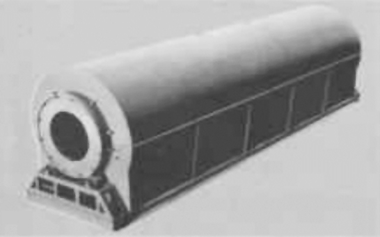
Screw-conveyor dryers
6.14.6 Fluid-bed dryers
Fluid bed dryers are found throughout all industries, from heavy mining through food, fine chemicals and pharmaceuticals. They provide an effective method of drying relatively free-flowing particles with a reasonably narrow particle size distribution. The feed may take the form of powders, granules, crystals, pre-forms and nonfriable agglomerates. Technology for processing of liquids in fluid bed systems using host media does exist, but it will not be discussed.
Fluid bed dryers can process a wide variation of feed rates, from a few pounds to several hundred tons per hour. Three principle types of fluid bed dryers exist. The first type is referred to as a static fluid bed because the dryer remains stationary during operation. Static fluid bed dryers can be continuous or batch operation and may be round or rectangular. The second type of fluid bed dryer is a vibrating fluid bed dryer, where the body of the dryer vibrates or oscillates, assisting the movement of material through the unit. Vibrating fluid bed dryers are almost exclusively rectangular in shape. The third type of fluid bed dryer fluidizes the material from the top by means of tubes that deflect on a solid pan lifting the material on the deflected airflow. This technology will not be discussed in this column. Fluid bed dryers may use a direct, indirect or combination heat source to provide the energy required to achieve drying.
Fluid bed types
Fluid bed processors may be configured for either continuous or batch operation.
Transport of the solids through the fluid bed may be achieved either by the fluidization alone or a combination of fluidization and vibration.
The flow of gas relative to the solids is characterized either as cross flow in a single tier fluid bed or as cross/counter-current in a multi-tier fluid bed.
There are two types of basic fluid bed designs according to the solids flow pattern in the dryer.
Continuous back mix flow
The continuous back-mix flow design for feeds that require a degree of drying before fluidization is established.
These are applied for feeds that are non-fluidizable in their original state, but become fluidizable after a short time in the dryer, e.g. after removal of surface volatiles from the particles.
The condition of the fluidizing material is kept well below this fluidization point. Proper fluidization is obtained by distributing the feed over the bed surface and designing the fluid bed to allow total solids mixing (back-mix flow) within its confines. The product temperature and moisture are uniform throughout the fluidized layer. Heating surfaces immersed in the fluidized layer improve the thermal efficiency and perfomance of this system. Back-mix fluid beds of both rectangular and circular designs are available
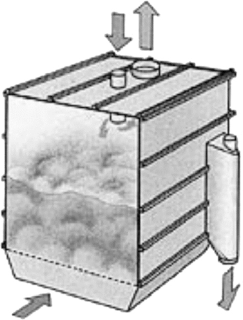
Back mix flow
Plug flow design
The plug flow design for feeds that are directly fluidizable on entering the fluid bed.
These are applied for feeds that are directly fluidizable. Plug flow of solids is obtained by designing the fluid bed with baffles to limit solids mixing in the horizontal direction. Thereby the residence time distribution of the solids becomes narrow. Plug flow fluid beds of either rectangular or circular designs are especially used for removal of bound volatiles or for heating and cooling. The volatile content and temperature vary uniformly as solids pass through the bed, and the plug flow enables the solids to come close to equilibrium with the incoming gas.

Plug mix flow
Plug flow may be achieved in different ways depending on the shape and size of the bed.
- In rectangular beds, baffles are often arranged to create an alternating flow of solids from side to side
- In circular beds, baffles are spiral
- In relatively small circular beds with high powder layers, baffles are radial
Vibrating fluid beds
This design, is basically of the plug flow type. It is especially applied for drying and cooling products that fluidize poorly due to a broad particle size distribution, highly irregular particle shape, or require relatively low fluidization velocities to prevent attrition. It operates with a shallow powder layer of less than 200 mm. This gives a much lower product residence time per unit bed area than non-vibrating beds which can have powder layers up to 1500 mm.
These fluidizers incorporate pressure shock resistance and sanitary features if clean operation is required.

Vibrating fluid bed
Contact fluidizers
This is a rectangular fluid bed dryer incorporating back-mix and plug flow sections. A rotary distributor disperses the wet feed evenly over the back-mix section equipped with contact heating surfaces immersed in the fluidized layer.
The heating surfaces provide a significant portion of the required energy, and therefore, it is possible to reduce both the temperature and the flow of gas through the system. This is particularly important for heat sensitive products.
Subsequent plug flow sections are used for postdrying and cooling, if required.
Advantages of the Contact Fluidizer – compared to fluid beds without heating surfaces, two-stage flash/fluid bed dryers, or rotary dryers – include its compact design, high thermal efficiency, and low gas throughput.
Multi-tier fluid beds
These fluid beds consist of two or more stacked fluid beds. The upper tier (back-mix or plug flow) is for predrying and the lower tier (plug flow) for postdrying. The drying gas travels counter-current to the solids. The gas leaving the lower tier contains sensible heat, which is transferred to the upper tier. Furthermore, each fluid bed may be provided with immersed heating surfaces. These designs result in a low gas throughput and high thermal efficiency which are of great importance in closed cycle drying systems.

Multi-tier fluid bed
6.14.7 Flash dryers
There are four factors, which influence the evaporation of moisture during flash drying.
Figure 6.67, illustrates the system consisting of Heater, Conditioner and the Disintegrator along with a Cyclone.

Flash dryer
- Moisture dispersion
Free flowing materials with moisture distributed over a relatively large surface area can be flash dried with little or no conditioning. Filter cakes and feeds with the consistency of mud can be conditioned for better drying by mixing them with previously dried material - Particle size
Shape and size are related to moisture dispersion. The smaller the particle, the more rapid the moisture removal. Thus, operations requiring simultaneous grinding and drying particularly adaptable to the flash drying process - Temperature differential
High inlet temperatures are utilized in flash drying. This is possible because the drying takes place so quickly. The material is dried and removed from the hot gas stream before it ever reaches the wet bulb temperature of the gas. It is common to use inlet design temperature of 650°C for highly combustible products such as sewage sludge and spent grain - Agitation
Rapid drying is also the result of maximum agitation or turbulence of the particles. High gas velocities in the flash dryer accomplish this
6.14.8 Spray dryers
Spray drying is one of the oldest forms of drying and one of the few technologies available for the conversion of a liquid, slurry or low viscosity paste to a dry solid (free-flowing powder) in one unit operation. Spray dryers are found in almost every industry, including mining and minerals, pharmaceuticals and detergents, paint and pigments, and food and dairy. They can dry at rates from several pounds to several tons per hour but become expensive to operate at the higher rates.

Spray atomizer
Spray dryers or towers, as they are sometimes called, atomize or spray the feed material into the drying chamber in fine droplets. They are continuous processing machines that come in a range of configurations. Traditional vertical configurations are broadly grouped into two categories depending on the method of introducing the feed. The first of these, tall-form dryers, use nozzles to atomize the feed. They are so termed due to the relatively narrow spray angle of the nozzle and the relative velocity of the droplets, requiring a tall drying chamber with a proportionally small diameter to provide sufficient residence time to achieve drying. The second group, which are shorter and fatter, use rotary disk atomizers (also referred to as centrifugal atomizers) to generate the spray. The angle of the rotary atomizer spray is flat with a wide spray pattern, requiring a large diameter tower that is relatively short. Other spray dryer configurations include box spray dryers, which rely on the same operating principles but extract the product from the bottom of the dryer housing by means of a conveyor, and pulse-combustion spray dryers. Rotary atomizer spray is flat with a wide spray pattern, and it requires a short, large-diameter tower.
The feed liquid is pumped into the atomization system that, by virtue of its technology, either will immediately atomize the feed to a spray of droplets (pressure nozzles) or feed the rotary disk that will atomize the product (rotary atomizer). Pressure nozzles rely on the pump supply pressure (or fluid such as compressed air in a two-fluid nozzle) to effect the atomization. Therefore, in tall-form dryers, high-pressure pumps or high pressure fluids usually are required for operation. A low-pressure pump is required for rotary atomizers to overcome the head associated with the change in elevation required to supply the feed from the ground to the top of the tower. The disk of the atomizer is driven at a high rate of revolution by an electric motor. The feed is metered onto the disk that creates a spray of material into the drying chamber by centrifugal forces.
The technology behind atomization, be it from pressure nozzles or rotary atomizers, is a science in itself. Without going into great detail, I can tell you that by adjusting parameters and components of the atomizer in conjunction with dryer configuration, you can effectively produce a final product that will meet specific product characteristics such as rehydration, moisture content, particle size and bulk density. Atomizer selection is based on the requirements of the final product, and each type of atomizer offers unique advantages outside of a common broad regime.
All atomizers (pressure or rotary) create a fine spray of feed into the tower’s drying chamber. In so doing, the surface area of the feed has been increased dramatically to allow for intimate contact between the carrier and product. In the pulse combustion dryer, the burner is used to both atomize the product and introduce the carrier into the system.
Spray dryers can be co-current, counter-current or fountain flow, depending on the material’s sensitivity to temperature, desired dry product characteristics and selection of the system. They may be direct or indirect and can use a variety of heat sources. In co-current systems, the hot gas (carrier) is introduced with the feed at the top of the tower and extracted at the discharge cone through an extraction duct. With counter-current systems, the carrier is introduced by means of a bustle above the dryer cone and exhausted from the top of the tower. With fountain flow, the product is sprayed vertically upward and changes direction within the drying chamber.
Pulse drying first was introduced as a commercially available method of drying in the early ‘80s. This method of spray drying uses a pulse combustion burner to both atomize the product and introduce the carrier into the system. This design obviates the requirement for both insulated hot gas ducting and high-pressure pumps and nozzles or rotary disk atomizers. The principle of atomization relies on the burner producing a high frequency combustion/detonation within the burner. The so-formed gases are channeled into a resonating chamber, where the frequency of the wave so formed is amplified. This wave atomizes the feed, which is metered in at low pressure, and entrains the particles in the hot gases, which are diluted by a secondary process air makeup within the burner/nozzle assembly to the required process temperature. The remainder of the dryer is identical to a tall-form co-current spray dryer.

Spray dryer
Spray dryers typically employ induced-draft fans to extract the moisture-laden air from the system. In some instances, special fans are installed to achieve dryer-specific operations such as air sweeps.
Due to the fine product that is produced on spray dryers, they inherently require dedicated dust-collection systems such as cyclones, bag houses, scrubbers and electrostatic precipitators.
Spray dryers are controlled by programmable logic controllers (PLCs) or solid-state controllers. In spray drying systems, the exhaust air temperature or humidity provides an input signal that, by way of a setpoint, will modulate the energy supplied to the process. Mechanically, these dryers are relatively low maintenance units. They can be fabricated from materials ranging from basic carbon steel to sophisticated duplex stainless steels. These dryers must be fully insulated to allow energy-efficient operation. Tall-from dryers have a pump and exhaust fan that require differing amounts of maintenance depending on the service, environment and abrasion characteristics of the product. Likewise, nozzles may wear — specifically, the orifice plates — and may require frequent replacement due to the wear adversely affecting the spray pattern. Dryers using rotary atomizers can become somewhat of a maintenance challenge, having to lift relatively large motors and gearboxes to the top of the tower for replacement. Facilities to assist in the maintenance and replacement of rotary atomizers can be designed into the system.
Tall-form dryers use nozzles to atomize the feed. The relatively narrow spray angle of the nozzle and relative velocity of the droplets require a tall drying chamber with a proportionally small diameter to provide sufficient residence time to achieve drying.
Spray dryers do have limitations. They are extremely energy intensive and have a correspondingly high operating cost. This is due to the fact that considerably more moisture is being thermally evaporated from the feed than in most other types of dryers. It is more expensive to thermally evaporate moisture than mechanically dewatering. Many spray dryers have problems relating to product buildup on the dryer walls. In some instances, this buildup is so significant it adds additional load to the tower, stressing the structure.
Spray dryers have a unique position in the arena of thermal drying. There is no other high volume method of producing a free-flowing powder from a liquid in one step. They offer unique, unmatched versatility in the production of powders and can control the powder characteristics to a specified requirement.
Conventional two-stage dryer
This is a spray dryer layout featuring either a rotary atomizer or spray nozzle atomizer. Powder discharged from the drying chamber can be further dried and cooled in a vibrating fluid bed. This two-stage drying concept achieves better overall heat economy and is suitable for many food and dairy products. When non-agglomerated powders of non-fat products are dried, a pneumatic transport system can replace the fluid bed.

Two-stage dryer
Compact dryer
This is a space saving spray dryer with integrated fluid bed. Atomization is created by either a rotary atomizer or spray nozzle atomizer. The location of the fluid bed within the drying chamber permits drying at lower temperature levels, resulting in higher thermal efficiencies and cooler conditions for handling powders. The plant can be equipped with pneumatic transport system for many powders or with an external vibrating fluid bed for agglomerated powders.

Compact dryer
Tall form dryer
A tower spray dryer with a top mounted nozzle assembly featuring a fines return capability. The atomized droplets dry while gently falling down the tower. Further drying and cooling are carried out in a vibrating fluid bed located under the tower. The tall form dryer is suited for both non-fat and fat-containing products, producing non-agglomerated and agglomerated free-flowing powders.

Tall dryer
Multi-stage dryer
This is a spray dryer with an integrated fluid bed. The spray is created by a spray nozzle atomizer. Operational flexibility enables production of a wide range of physical properties. The process produces non-dusty, free flowing agglomerated powders with high flavor retention. It operates with low outlet temperatures, achieving high thermal efficiency. Dry ingredients for additional flavor or nutrient fortification can be added within the system to further promote capabilities and improve formulation efficiencies. This design concept is successful for drying high fats, hygroscopic, and sticky products that are difficult to handle in more conventional designs.

Multi stage dryer
6.14.9 Thin-film dryers
Thin film evaporators, thin film dryers and short path evaporators all work on basis of processing a product in a thin turbulent film. The heart of the thin film technology is the rotor which creates the thin product film. The product is picked up by the rotor blades and immediately formed into a thin turbulent film on the heat transfer surface (Figure 6.74). Due to the low film thickness (from 0,5 mm) the heat and mass transfer rates are significantly improved compared to non agitated heat transfer equipment. The volatile component of the feed stock is therefore very quickly evaporated. For this reason the thin film technology has become a generally recognised and accepted solution for the most difficult and demanding processing problems in the areas of distillation, concentration, degassing, drying, cooling and reaction. Without thin film technology the efficient processing of many products from the chemical, pharmaceutical, food and polymer industries be either extremely difficult or impossible.
Commonly thin film equipment is jacketed on the thermal surface. Mostly a double jacket is used for steam or liquid heat transfer agents. When working with high pressure, half coils welded to the inner shell are required.

Thin film dryer
Features of inductive heating
Thin film equipment with an inductive heating system is designed without any jacket in the evaporation zone. Inductive heating is generated in the inner shell by wrap-around copper coils. Inductive heating permits temperatures of up to 500 °C for any type of thin film equipment, either of cylindrical or conical design of the evaporation zone.
Thin film technology is commonly the last stage of a thermal separation process requiring the highest temperature. The possibility of avoiding installing a special hot oil system for this last stage can often prove an economically interesting alternative for the following reasons:
- High operational safety (no rotating parts, e. g. pumps, no oil leakages)
- Easy erection (control cabinet only)
- Smaller space requirements (no hot-oil unit, no piping)
- Reduced inspection and testing by minimising the number of pressure retaining parts
- High specific heat transfer rates
- Short heat up time
- High overall thermal efficiency due to reduced radiation from a hot oil unit and associated pipe work
- Fine temperature control
- Safety requirements for hot oil are not required
6.14.10 Drum dryers
A drum dryer consists of one or more heated metal rolls on the outside of which a thin layer of liquid is evaporated to dryness. Dried solid is scraped off the rolls as they slowly revolve.
Continuous operation permits mass:
- Production
- Adjustment of temperature, volume, rotation speed and humidity of drying
- Easily carried out to meet the required conditions
- Handles bulky products and materials while assisting to break up the mass
- Agglomerations
- Simple construction, easy operation and maintenance

Drum dryer
7.1 Applications of thermodynamics principles
7.1.1 Nozzles
A device, in which kinetic energy and internal energy of a fluid are interchanged as a result of changing cross-sectional area available for flow, is termed a nozzle. It increases the velocity of the fluid at the expense of pressure. Nozzles and diffusers are commonly utilized in jet engines, rockets, spacecraft, and even garden hoses
A convergent nozzle is one in which with an incompressible fluid the nozzle area continues to decrease and velocity increases as the pressure decreases. On the other hand, for compressible fluids, the area first decreases and then increases so that the nozzle has a converging section followed by a divergent section. Such a nozzle is called a convergent divergent nozzle.
A converging duct is a nozzle for subsonic flow (M < 1).
A diverging duct is a nozzle for a supersonic flow (M > 1).

Nozzle

Convergent nozzle

Convergent-divergent nozzle
Shapes and sizes of nozzle
Nozzles come in a variety of shapes and sizes depending on the mission of the aircraft. Simple turbojets and turboprops have a fixed geometry convergent nozzle as shown in figure 7.2. Afterburning turbojets and turbofans often have a variable geometry Convergent-Divergent (CD) nozzle as shown on the figure 7.3. In this nozzle, the flow first converges down to the minimum area, or throat, and then is expanded through the divergent section to the exit at the right. The variable geometry causes these nozzles to be heavy, but provides efficient engine operation over a wider airflow range than a simple fixed nozzle. Rocket engines usually have a fixed geometry CD nozzle with a much larger divergent section than is required for a gas turbine.
Because the nozzle conducts the hot exhaust back to the free stream, there can be serious interactions between the engine exhaust flow and the airflow around the aircraft. On fighter aircraft, in particular, large drag penalties can occur near the nozzle exits. A typical nozzle-after body configuration is shown in the upper right for an F-15 with experimental maneuvering nozzles.
7.1.2 Diffusers
The diffuser is the gradually expanding passage following the test section in which the flow speed decreases and the pressure rises. The recovery of pressure from kinetic energy reduces the power needed to drive the tunnel: in the case of open-circuit tunnels the diffuser also reduces drafts in the laboratory. The pressure rise is less than that given by Bernoulli’s equation, because of losses due to skin friction and resulting growth of boundary-layer displacement thickness.
The cross-sectional area of a diffuser increases in the flow direction for subsonic flows and decreases for supersonic flows.
A converging duct is a nozzle for a supersonic flow (M > 1).
A diverging duct is a nozzle for a subsonic flow (M < 1).

Diffuser
Supersonic diffuser
Supersonic tunnels, in which a diverging diffuser after the test section would produce a further increase in Mach number, are equipped with a second throat at the end of the test section figure 7.5. The first throat is the one upstream of the test section through which the flow accelerates through the speed of sound. In the converging section leading to the second throat the flow is decelerated to slightly above sonic speed (obeying the one-dimensional inviscid compressible flow equations to a first approximation); in the diverging section downstream of the throat the Mach number rises again, until a shock wave or waves produce a reduction to subsonic speed. It may be shown that a shock wave in the converging portion of the second throat would be unstable, and in practice the second-throat Mach number is chosen large enough for the breakdown shock system to be located well downstream of the throat, to ensure stability under all operating conditions.
When the tunnel is started up, the second throat must be rather larger than the first throat in order for the latter to choke first, so that supersonic flow can be established in the test section. The inviscid-flow equations are not accurate during startup because a strong shock wave passes down the test section, reducing the speed below that of sound and usually causing massive boundary-layer separation. Therefore the second throat has to be significantly larger than the first, and to achieve the best possible supersonic diffusion in tunnels for high supersonic speeds the second throat is closed in after starting (reducing the local Mach number), by adjusting the shape of the walls. This is cost-effective only in large tunnels or if drive power is restricted.

Supersonic diffuser
Subsonic diffuser
The usual design rule for subsonic diffusers is that the total included angle of a portion of a circular cone with the same length and area ratio as the diffuser should not exceed 5 deg. This is well below the angle for maximum pressure recovery, which is nearer 10 deg., but at angles of more than about 5 deg. the boundary layer is close enough to separation for the flow to be unsteady. The 5 deg. rule will fail if the test section is unusually long, so that the boundary-layer thickness at entry to the diffuser is unusually large. (We expect the behavior of boundary layers in adverse pressure gradient to depend on some dimensionless parameter such as (δ/UCL)dUCL/dx, which must be small enough to avoid separation. Here δ and UCL are strictly the local boundary layer thickness and centerline velocity – related by Bernoulli’s equation to the pressure gradient, which is what really matters – but the evolution of δ is determined by its value at the beginning of the diffuser.)

Subsonic diffuser
7.1.3 Throttling valve
The critical flow nozzle allows the steam to reach sonic velocity at the throat of the nozzle at a very low upstream pressure. Due to the laws of physics the sonic velocity at the throat cannot be exceeded. As the upstream pressure increases the volumetric flow rate does not change, but the density of the steam increases with increasing pressure and thus the mass flow rate is proportional to the upstream pressure. A conical diffuser reduces the sonic velocity at the throat back down to the flow velocity in the pipe while recovering up to 90% of the upstream pressure.
Because of the pressure loss across the nozzle this type of meter can only be used in applications where steam is injected into a lower pressure area. Typical applications include humidification, surging tanks, atmospheric blanchers, steam eductors, steam injection into process ovens, and any other application where steam is exhausted through a manifold or nozzles to a lower pressure.

Throttling process
7.2 Compressor
A machine, used to provide gas at high pressure by the application of work from the external agency on the gas, is known as a compressor.
The compressor is used for the following purposes:
- Transporting fluids
- Providing high pressure for carrying out reactions and separation processes
- For pneumatic instruments
- For transferring mechanical energy to a fluid for agitation, solid particle transportation, etc
7.2.1 Types of compressors
Variable area nozzle compressor
These types of Compressor are used when motive, suction, or discharge conditions vary and it is necessary to control the discharge pressure or flow. Control of this compressor is accomplished by a spindle, which regulates the motive gas flow through the nozzle.
Unlike a control valve where energy is lost, the spindle reduces flow without reducing the available energy. Control of the spindle can activated by temperature, pressure, flow or suction to motive ratio. Variation of the spindle travel can be achieved with any suitable actuator.
Fixed nozzle compressor
Fixed Nozzle Compressors have no regulating spindle, and are generally used where operating conditions are stable.
Single and double acting compressors
In the single acting compressor the air is admitted to one side of piston only while in case of double acting air is admitted to each side of piston alternatively so one side of piston performs suction stroke and the air on the other side is compressed.
Multi-stage compressor
In a single-stage compressor, the whole range of compression is accomplished in one cylinder, i.e. in one-step or stage. Contrary to this, if the whole range of compression (from initial to final pressure) is accomplished in a unit in which there are two or more cylinders in series, each compressing over only a part of total pressure range, then the compressing system is termed as multi-stage compression.
The advantages of multi-stage compression are:
- Reduction of driving power required for given pressure ratio
- Improved volumetric efficiency for a given pressure ratio
- Permits high delivery pressure with reasonable volumetric efficiency
- Size and strength of cylinders can be adjusted to suit volume and pressure of air
- Multi-cylinders give better mechanical balance and improved cooling during compression
7.2.2 Compressing devices
The different types of compressing devices are:
Centrifugal fans
A centrifugal fan has an impeller with a number of blades around the periphery, and the impeller rotates in a scroll or volute shaped casing, and it is this casing, which identifies the centrifugal fan. As the impeller rotates, air is thrown from the blade tips centrifugally into the volute shaped casing (snail shell) and out through the discharge opening, and at the same time more air is drawn into the ‘eye’ of the impeller through a central inlet opening in the side of the casing, thus creating a continuous flow of air through the fan impeller and casing.
The volute shape of the casing helps to transform some of the velocity pressure of the air leaving the impeller into useful static pressure to overcome resistance to airflow in the ducting system to which the fan is connected. In normal ventilation work, a centrifugal fan would be used for static pressures (system resistances) up to about 750 Pa(=N/m2). A point to note is that the air flow through a centrifugal fan cannot be reversed.

Centrifugal fan
The advantages are:
- Provides pulsation-free air 24 hours a day
- 100% continuous duty
- Quiet operation
- Energy efficient at full load
- Extended service intervals
- Reliable long life
- Improved air quality
Centrifugal compressors or turbo-compressors
Centrifugal compressor process simulation can be configured to compress a variety of process gases by varying the molecular weight. The default configuration is for dry air.
Air passes through a suction valve before entering the suction drum. If the process gas demand is less than the minimum recommended compressor flow (surge point), then the makeup gas will mix with the kickback flow. The gas then passes through a cooler, where the temperature is lowered to prevent excessive compressor discharge temperatures. Any condensate present in the gas will be knocked out in the suction drum before the gas enters the compressor.
The compressed gas is then drawn off from the discharge side of the compressor by users. In the event of a decrease in process gas demand by the users, a minimum compressor flow line (kickback or spillback) is provided to allow the recycling of gas to prevent compressor surging. A vent/flare line is also provided to prevent an over-pressuring of the system.

Centrifugal compressor
Axial compressors
The axial compressor is one of the main components of modern gas turbines used as drive for generators in the energy supply and as jet engines in aviation, respectively. For reasons of a reduction of weight and costs a reduction of the stage number by an increase of the stage pressure ratio is desired along with constantly high stage efficiency. This tendency increases the danger of flow instabilities, which means a considerable risk for the axial compressor and which may lead to aggravating damages.
An axial flow compressor generally contains several ‘stages’. Each stage consists of a rotor, which is mounted on a central shaft, and rotates at high speed, together with a stator, which is fixed to the casing. Both rotor and stator have many aerodynamically profiled blades designed to generate a pressure difference across the stage. The attainable pressure rise per stage is limited by the aerodynamic efficiency of the blade and many stages are required to build up a useful pressure difference.
The axial-flow compressor is not a positive-displacement device and will not operate for all flow conditions. At high loading and low flow rates it will surge as the flow pattern through the blading breaks down.

Axial compressor
Advantages of axial compressors:
- High overall π
- High η
- Small front area (High mass flux)
Reciprocating compressors
A reciprocating compressor is used to boost the pressure of the flow media for use as a seal gas by the flow compressor. This unit can be used to pressurize air for use in the loop. (Air is sometimes used for testing that does not involve in-line inspection tools.) Another reciprocating unit is used for pressurizing fuel gas from its supply pressure of under 50 psi to the pressure required by the flow compressor, nominally 170 psi. Each compressor system is self-contained with its own coolers, scrubbers, and filters.
The process gas to be compressed enters the suction of the first stage of the reciprocating compressor through a suction pressure control valve. The make-up process gas is mixed with the kickback flow before passing through the inlet cooler.
The process gas leaving the first stage of the compressor passes through an inter cooler before being compressed by the second stage of the compressor.
The compressed process gas is then drawn off by users from the discharge of the second stage. Excess gas may either by sent back to the suction of the first stage through the discharge pressure control valve, or may be vented.

Reciprocating compressors
Applications of reciprocating compressors
Refining (Hydro cracking, HDT, HDS, reforming, recovery, and recycle applications): Horizontal and balanced opposed compressors with unit power capability reaching 35,000 kW.
Petrochemicals and chemicals balanced opposed compressors for: ammonia synthesis plants and urea synthesis plants with capacities up to 1,000 t/d per machine, polymer production plants, and liquefied gas storage plants. Special horizontal opposed hyper compressors for LDPE (low-density polyethylene) plants reaching over 3,500 bars.
Special service for corrosive and toxic gases.
Natural gas and oil fields horizontal balanced – opposed compressors for re-injection, gas lift, gathering, boosting, storage and treating services, both onshore and offshore. The compressors can be skid mounted in integral systems to form completely self-contained packaged units.
CNG compressors for bottling natural gas for automotive service; ‘Cubogas’ modular refueling stations (as many as 1,000 vehicles per day); turnkey stations for refueling as many as 2,500 vehicles per day.
Rotary compressors
The compression chamber is a toroidal channel in which an impeller rotates. The gas trapped between the vanes is centrifugally forced to the periphery of the chamber and swirls around the core before it is caught again by the next vane on the wheel, repeating the process all around the channel, and transforming the kinetic energy into pressure. A stripper separates the inlet from the outlet ports and helps in guiding the gas flow from suction to discharge. The clearance between the impeller and the stripper is very tight to limit the gas slippage.
The location, orientation, area of inlet/outlet ports, the geometry of the vanes (bending radius, height, penetration, angle), the shape and area of the chamber, and the shape of the channel impart different compressor characteristics (flow rate, pressure, efficiency), offering multiple solutions for dealing with varied process conditions.

Rotary compressor
The benefits of rotary compressors over reciprocating compressors are:
- Continuous and smooth operations
- Higher efficiency as a result of less power consumption
- Fewer moving parts leading to greater reliability
- Lighter weight and more compact size
- Quieter operation
Application
- Boosting and recycling of hydrogen mixtures and hydrocarbon gases
- Gas compression in industrial processes
- Gas phase reactor recycling
- Molecular sieve regeneration in gas drying processes
- Vent/Purge gas recovery
- Fuel gas boosting for GT feed
- For ventilation purpose in closed shed and other industries and also in furnaces
Jet compressors
Jet compressors utilize the energy of steam, gas, or air, under pressure, to circulate steam, boost low-pressure steam, and mix gases in desired proportion. In all of the processes where jet compressors are applied, they not only perform the primary function of compressing and mixing gases, but also take the place of a reducing valve and salvage much of the energy lost in the reduction of operating medium pressure.
Basically, jet compressors consist of an expanding nozzle, diffuser, and body. They are also equipped with manually or automatically controlled adjusting spindles for regulating the volume of flow through the nozzle. Manually controlled units are recommended for use when pressures do not vary. Automatically controlled units are recommended when capacities or discharge pressures vary. Units can be made of corrosion-resistant materials.
In operation, jet compressors utilize a jet of high-pressure gas as an operating force to entrain a low-pressure gas, mix the two, and bring the pressure to an intermediate point. Gases can be steam, air, propane, or others. When both fluids are steam, the unit is known generally as a Thermo compressor. These Thermo compressors are used as energy savers, recovering low-pressure ‘waste’ steam by combining it with higher-pressure steam to raise the discharge pressure so the mixture can be re-used in a process.

Jet compressors
Applications of Jet compressors
JET Compressor is an ideal device for:
- Gas recovery from marginal Wells
- Flare gas recovery / flare gas elimination
- Boosting capacity of mechanical Compressors
- Compression of overhead gas to MEA scrubbers
- Gas compression between two stages of a two stage Combustor
- Compression of waste gas into a flare header system
- Low pressure oil well boosting
7.3 Ejector-system
The operating principle of an ejector is basically to convert pressure energy of the motive steam into velocity. This occurs by adiabatic expansion from motive steam pressure to suction-load operating pressure. This adiabatic expansion occurs across a con-verging and diverging nozzle. This results in supersonic velocity off the motive nozzle, typically in the range of mach 3 to 4.
In reality, the motive steam expands to a pressure lower than the suction load pressure. This creates a low-pressure zone for pulling the suction load into the ejector. High-velocity motive steam entrains and mixes with the suction gas load. The resulting mixture’s velocity is still supersonic. Next, the mixture enters a venturi where the high velocity reconverts to pressure. In the converging region, velocity is converted o pressure as cross-sectional flow area is reduced. At the throat section, a normal shock wave is established. Here, a significant in pressure and loss of velocity across the shock wave occurs. Flow across the shock wave goes from supersonic ahead of the shock wave, to sonic at the shock wave and subsonic after the shock wave. In the diverging section, velocity is further reduced and converted into pressure. Motive pressure, temperature and quality are critical variables for proper ejector operating performance. The amount of motive steam used is a function of required ejector performance. The nozzle throat is an orifice and its diameter is designed to pass the specified quantity of motive steam, required to effect sufficient compression across the ejector. Calculation of a required motive nozzle throat diameter is based on the necessary amount of motive steam, its pressure and specific volume.

Ejector
Motive steam quality is important because moisture droplets affect the amount of steam passing through the nozzle. High-velocity liquid droplets also prematurely erode ejector internals, reducing performance. Operating a vacuum unit requires an ejector system to perform over a wide range of conditions. The ejector system must be stable over all anticipated operating conditions. Also, an accurate understanding of ejector system backpressure for all operating modes is necessary for stable operation. An ejector does not create its discharge pressure, it is simply supplied with enough motive steam to entrain and compress its suction load to a required discharge pressure. If the ejector backpressure is higher than the discharge pressure it can achieve, then the ejector ‘breaks’ operation and the entire ejector system may be unstable.
7.4 Heat conversion and power cycles
7.4.1 Heat engines
Heat engines convert heat energy into mechanical energy. Examples include steam engines, steam and gas turbines, spark-ignition and diesel engines, and the ‘external combustion’ engine or Stirling engine. Such engines can provide motive power for transportation, to operate machinery, or to produce electricity.
All heat engines operate in a cycle of repeated sequences of heating (or compressing) and pressurizing the working fluid, the performance of mechanical work, and rejecting unused or waste heat to a ‘sink.’ At the beginning of each cycle, energy is added to the fluid forcing it to expand under high pressure so that the fluid ‘performs’ mechanical work. The thermal energy contained in the pressurized fluid is converted to kinetic energy. The fluid then looses pressure, and after unused energy (in the form of heat) is rejected, it must then be reheated or recompressed to restore it to high pressure.
Heat engines cannot convert all the input energy to useful mechanical energy in the same cycle; some amount, in the form of heat, is always not available for the immediate performance of mechanical work. The fraction of thermal energy that is converted to net mechanical work is called the thermal efficiency of the heat engine. The maximum possible efficiency of a heat engine is that of a hypothetical (ideal) cycle, called the Carnot Cycle. Practical heat engines operate on less efficient cycles (such as the Rankine, Brayton, or Stirling) but in general, the highest thermal efficiency is achieved when the input temperature is as high as possible and the sink temperature is as low as possible.
The ‘waste’ or rejected heat (to the ‘sink) can be used for other purposes, including pressurizing a different working fluid, which operates a different heat-engine (vapor turbine) cycle, or simply for heating. Renewable sources of heat or fuels, such as solar or geothermal energy and biomass (as well as fossil fuels) can power heat engines. The following is a brief description of four types of heat engines, the Rankine, Stirling, Brayton, and the newly developed, and highly efficient, Kalina, that can be used or are being investigated for converting renewable sources of energy to useful energy.

Heat engine
Rankine cycle engines
The Rankine cycle system uses a liquid that evaporates when heated and expands to produce work, such as turning a turbine, which when connected to a generator, produces electricity. The exhaust vapor expelled from the turbine condenses and the liquid is pumped back to the boiler to repeat the cycle. The working fluid most commonly used is water, though other liquids can also be used. Rankine cycle design is used by most commercial electric power plants. The traditional steam locomotive is also a common form of the Rankine cycle engine. The Rankine engine itself can be either a piston engine or a turbine.
Stirling cycle engines
The Stirling cycle engine (also called an ‘external’ combustion engine) differs from the Rankine in that it uses a gas, such as air, helium, or hydrogen, instead of a liquid, as its working fluid. Concentrated sunlight, biomass, or fossil fuels are sources potential fuels to provide external heat to one cylinder. This causes the gas to alternately expand and contract, moving a displacer piston back and forth between a heated and an unheated cylinder.
Brayton cycle engines
Brayton cycle systems, which incorporate a turbine, also use a gas as the working medium. There are open-cycle and closed-cycle Brayton systems. The gas turbine is a common example of an open-cycle Brayton system. Air is drawn into a compressor, heated and expanded through a turbine, and exhausted into the atmosphere. The closed-cycle Brayton system may use air, or a more efficient gas, such as hydrogen or helium. The gas in the closed-cycle system, however, gives up some of its heat in a heat exchanger after it leaves the turbine. It then returns to the compressor to start the cycle again.
Kalina cycle engines
The Kalina cycle engine, which is at least 10 percent more efficient than the other heat engines, is simple in design and can use readily available, off-the-shelf components. This new technology is similar to the Rankine cycle except that it heats two fluids, such as ammonia and water, instead of one. Instead of being discarded as waste at the turbine exhaust, the dual component vapor (70% ammonia, 30% water) enters a distillation subsystem. This subsystem creates three additional mixtures. One is a 40/60 mixture, which can be completely condensed against normal cooling sources. After condensing, it is pumped to a higher pressure, where it is mixed with a rich vapor produced during the distillation process. This recreates the 70/30 working fluid. The elevated pressure completely condenses the working fluid and returns it to the boiler to complete the cycle. The mixture’s composition varies throughout the cycle. The advantages of this process include variable temperature boiling and condensing, and a high level of recuperation.
7.4.2 Internal combustion engines
An internal combustion engine burns a mixture of fuel and air. Typical IC engines are classified as Spark and Compression ignition engines.
The simplest model for IC engines is the air-standard model, which assumes that:
- The system is closed
- Air is the working fluid and is modeled as an ideal gas throughout the cycle
- Compression and expansion processes are isentropic
- A reversible heat transfer process characterizes the combustion of fuel and air
- Heat rejection takes place reversibly and at constant volume
The Otto cycle is used to model a basic Spark Ignition engine, while the Diesel cycle is the basic model for the Compression Ignition engine.
Spark ignition engine (Otto cycle)
The most common type is a four-stroke engine. A piston slides in and out of a cylinder. Two or more valves allow the fuel and the air to enter the cylinder and the gases that form when the fuel and air burn to leave the cylinder. As the piston slides back and forth inside the cylinder, the volume that the gases can occupy changes drastically.
The process of converting heat into work begins when the piston is pulled out of the cylinder, expanding the enclosed space and allowing fuel and air to flow into that space through a valve. This motion is called the intake stroke or induction stroke. Next, the fuel and the air mixture are squeezed together by pushing the piston into the cylinder. This is called the compression stroke. At the end of the compression stroke, with the fuel and the air mixture squeezed as tightly as possible, the spark plug at the sealed end of the cylinder fires and ignites the mixture. The hot burning fuel has an enormous pressure and it pushes the piston out of the cylinder. This power stroke is what provides power to the engine and the attached machinery. Finally, the burned gas is squeezed out of the cylinder through another valve in the exhaust stroke. These four strokes repeat over and over again. Most internal combustion engines have at least four cylinders and pistons. There is always at least one cylinder going through the power stroke and it can carry the other cylinders through the non-power strokes. The maximum efficiency of such an engine is emax = (Tignition – Tair)/Tignition where Tignition is the temperature of the fuel-air mixture after ignition. To maximize the fuel efficiency, you have to create the hottest possible fuel air mixture after ignition. The highest efficiency that has been achieved is approximately 50% of emax.

Spark ignition engine

Otto cycle
Compression ignition engines (Diesel cycle)
In the Diesel, the fuel is not mixed with the air entering the cylinder during the intake stroke. Air alone is compressed during the compression stroke. The Diesel fuel oil is injected or sprayed into the cylinder at the end of the compression stroke. The Diesel Cycle differs from the Otto Cycle only in the modeling of the combustion process. In a Diesel Cycle, it is assumed to occur as a reversible constant pressure heat addition process, while in an Otto Cycle, the volume is assumed constant.
The four steps of the air-standard Diesel Cycle are outlined below:
- (1-2) Isentropic Compression (Compression Stroke)
- (2-3) Reversible, constant pressure heat addition (Ignition)
- (3-4) Isentropic expansion to initial volume (Power Stroke)
- (4-1) Reversible constant-volume heat rejection (Exhaust)
In diesel engines, compression ratios are as high as (22.5 to 1) and provide pressures of (500psi) at the end of the compression stroke. Through the compression process, the air can be heated up (1000 degrees F). This temperature is high enough to spontaneously ignite the fuel as it is injected into the cylinder. The high pressure of the explosion forces the piston down as in the gasoline engine.

Diesel cycle
7.4.3 Steam turbine
The steam turbine obtains its motive power from the change of momentum of a jet of steam flowing over a curved vane. The steam jet, in moving over the curved surface of the blade, exerts a pressure on the blade owing to its centrifugal force. This centrifugal pressure is exerted normal to the blade surface and acts along the whole length of the blade; the result of this centrifugal pressure plus the effect of change of velocity is the motive force on the blade. This motive power enables the turbine to drive the electric generator.
A steam turbine consists of a pair of blade rings consisting of a fixed ring of blades and moving ring. Both the moving and fixed blades are designed so that the jet shall not strike the blade but will merely glide over it in parallel direction. The fixed blades are fixed to the turbine casing and face the moving blades in opposite direction. The object of fixed blade is to receive steam jet discharging from the moving blade ring and to divert it to the next ring of moving blade by changing its direction. This diversion may continue over several rings of moving and fixed blades until the whole of K.E. of the steam is expanded.

Steam turbine
Single stage turbines
Dresser-Rand produces the most complete line of single stage turbines for driving pumps, blowers, compressors, generators, fans, sugar mills, paper mills – virtually any potential application. We combine technological expertise with manufacturing skills to offer the very finest standard turbines available today.
Multistage steam turbines
Our Industrial Standard Multi-Stage Steam Turbine line offers you up to nine stages. And, to meet the variety of energy conditions in industrial environments, we offer 13 frame sizes that produce up to 6000 KW. These turbines operate at speeds up to 8000 RPM, with steam inlet conditions to 700 PSIG @ 825°F; and exhaust conditions to 300 lbs.
Exhaust nozzle
Gas turbine engines for aircraft have an exhaust system, which passes the turbine discharge gases to atmosphere at a velocity in the required direction, to provide the necessary thrust. The design of the exhaust system, therefore, exerts a considerable influence on the performance of the engine. The cross sectional areas of the jet pipe and propelling or outlet nozzle affect turbine entry temperature, the mass flow rate, and the velocity and pressure of the exhaust jet.
A basic exhaust system function is to form the correct outlet area and to prevent heat conduction to the rest of the aircraft. The use of a thrust reverser (to help slow the aircraft on landing), a noise suppresser (to reduce the noisy exhaust jet) or a variable area outlet (to improve the efficiency of the engine over a wider range of operating conditions) produces a more complex exhaust system.
Afterburners
In addition to the basic components of a gas turbine engine, one other process is occasionally employed to increase the thrust of a given engine. Afterburning (or reheat) is a method of augmenting the basic thrust of an engine to improve the aircraft takeoff, climb and (for military aircraft) combat performance.
Afterburning consists of the introduction and burning of raw fuel between the engine turbine and the jet pipe propelling nozzle, utilizing the unburned oxygen in the exhaust gas to support combustion. The resultant increase in the temperature of the exhaust gas increases the velocity of the jet leaving the propelling nozzle and therefore increases the engine thrust. This increased thrust could be obtained by the use of a larger engine, but this would increase the weight, frontal area and overall fuel consumption. Afterburning provides the best method of thrust augmentation for short periods.
Afterburners are very inefficient as they require a disproportionate increase in fuel consumption for the extra thrust they produce. Afterburning is used in cases where fuel efficiency is not critical, such as when aircraft take off from short runways, and in combat, where a rapid increase in speed may occasionally be required.

Afterburners
7.4.4 Jet engines
The main function of any aero plane propulsion system is to provide a force to overcome the aircraft drag, this force is called thrust. Both propeller driven aircraft and jet engines derive their thrust from accelerating a stream of air – the main difference between the two is the amount of air accelerated. A propeller accelerates a large volume of air by a small amount, whereas a jet engine accelerates a small volume of air by a large amount. This can be understood by Newton’s 2nd law of motion which is summarized by the equation F=ma (force = mass x acceleration). Basically the force or thrust (F) is created by accelerating the mass of air (m) by the acceleration (a).
Given that thrust is proportional to airflow rate and that engines must be designed to give large thrust per unit engine size, it follows that the jet engine designer will generally attempt to maximize the airflow per unit size of the engine. This means maximizing the speed at which the air can enter the engine, and the fraction of the inlet area that can be devoted to airflow. Gas turbine engines are generally far superior to piston engines in these respects; therefore piston-type jet engines have not been developed.
Air passing through the engine has to be accelerated; this means that the velocity or kinetic energy of the air must be increased. First, the pressure energy is raised, followed by the addition of heat energy, before final conversion back to kinetic energy in the form of a high velocity jet.
The basic mechanical arrangement of a gas turbine is relatively simple. It consists of only four parts:
- The compressor, which is used to increase the pressure (and temperature) of the inlet air
- One or a number of combustion chambers in which fuel is injected into the high-pressure air as a fine spray, and burned, thereby heating the air. The pressure remains (nearly) constant during combustion, but as the temperature rises, each kilogram of hot air needs to occupy a larger volume than it did when cold and therefore expands through the turbine
- The turbine, which converts some of this temperature rise to rotational energy. This energy is used to drive the compressor
- The exhaust nozzle which accelerates the air using the remainder of the energy added in the combustor, producing a high velocity jet exhaust

Jet engine
7.4.5 The compressor
In the gas turbine engine, compression of the air is effected by one of two basic types of compressor, one giving centrifugal flow and the other axial flow. Both types are driven by the engine turbine and are usually coupled direct to the turbine shaft.
The centrifugal flow compressor employs an impeller to accelerate the air and a diffuser to produce the required pressure rise. Flow exit’s a centrifugal compressor radially (at 90° to the flight direction) and it must therefore be redirected back towards the combustion chamber, resulting in a drop in efficiency. The axial flow compressor employs alternate rows of rotating (rotor) blades, to accelerate the air, and stationary (stator) vanes, to diffuse the air, until the required pressure rise is obtained.
The pressure rise that may be obtained in a single stage of an axial compressor is far less than the pressure rise achievable in a single centrifugal stage. This means that for the same pressure rise, an axial compressor needs many stages, but a centrifugal compressor may need only one or two

Compressor
An engine design using a centrifugal compressor will generally have a larger frontal area than one using an axial compressor. This is partly a consequence of the design of a centrifugal impeller, and partly a result of the need for the diffuser to redirect the flow back towards the combustion chamber. As the axial compressor needs more stages than a centrifugal compressor for the equivalent pressure rise, an engine designed with an axial compressor will be longer and thinner than one designed using a centrifugal compressor. This, plus the ability to increase the overall pressure ratio in an axial compressor by the addition of extra stages, has led to the use of axial compressors in most engine designs, however, the centrifugal compressor is still favored for smaller engines where it’s simplicity, ruggedness and ease of manufacture outweigh any other disadvantages.
Combustion chamber
The combustion chamber has the difficult task of burning large quantities of fuel, supplied through fuel spray nozzles, with extensive volumes of air, supplied by the compressor, and releasing the resulting heat in such a manner that the air is expanded and accelerated to give a smooth stream of uniformly heated gas. This task must be accomplished with the minimum loss in pressure and with the maximum heat release within the limited space available.
The amount of fuel added to the air will depend upon the temperature rise required. However, the maximum temperature is limited to within the range of 850 to 1700 °C by the materials from which the turbine blades and nozzles are made. The air has already been heated to between 200 and 550 °C by the work done in the compressor, giving a temperature rise requirement of 650 to 1150 °C from the combustion process. Since the gas temperature determines the engine thrust, the combustion chamber must be capable of maintaining stable and efficient combustion over a wide range of engine operating conditions.
The temperature of the gas after combustion is about 1800 to 2000 °C, which is far too hot for entry to the nozzle guide vanes of the turbine. The air not used for combustion, which amounts to about 60 percent of the total airflow, is therefore introduced progressively into the flame tube. Approximately one third of this gas is used to lower the temperature inside the combustor; the remainder is used for cooling the walls of the flame tube.
There are three main types of combustion chamber in use for gas turbine engines. These are the multiple chambers, the can-annular chamber and the annular chamber.
Multiple chambers
This type of combustion chamber is used on centrifugal compressor engines and the earlier types of axial flow compressor engines. It is a direct development of the early type of Whittle engine combustion chamber. Chambers are disposed radially around the engine and compressor delivery air is directed by ducts into the individual chambers. Each chamber has an inner flame tube around which there is an air casing. The separate flame tubes are all interconnected. This allows each tube to operate at the same pressure and also allows combustion to propagate around the flame tubes during engine starting.

Multiple chambers
Can-annular chamber
This type of combustion chamber bridges the evolutionary gap between multiple and annular types. A number of flame tubes are fitted inside a common air casing. The airflow is similar to that already described. This arrangement combines the ease of overhaul and testing of the multiple systems with the compactness of the annular system.

Can-annular chamber
Annular chamber
This type of combustion chamber consists of a single flame tube, completely annular in form, which is contained in an inner and outer casing. The main advantage of the annular combustion chamber is that for the same power output, the length of the chamber is only 75 per cent of that of a can-annular system of the same diameter, resulting in a considerable saving in weight and cost. Another advantage is the elimination of combustion propagation problems from chamber to chamber.

Annular chamber
7.4.6 Rocket engines
One of the most amazing efforts man has ever undertaken is the exploration of space. A big part of the amazement is the complexity. Space exploration is complicated because there are so many problems to solve and obstacles to overcome.
The gray areas to be confronted are:
- The vacuum of space
- Heat management problems
- The difficulty of re-entry
- Orbital mechanics
- Micrometeorites and space debris
- Cosmic and solar radiation
- The logistics of having restroom facilities in a weightless environment
But the major problem of all is harnessing enough energy simply to get a spaceship off the ground. That is where rocket engines come in.
The basics
Rocket engines are fundamentally different. Rocket engines are reaction engines. The basic principle driving a rocket engine is the famous Newtonian principle that ‘to every action there is an equal and opposite reaction.’ A rocket engine is throwing mass in one direction and benefiting from the reaction that occurs in the other direction as a result.
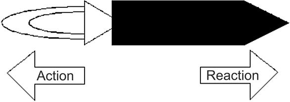
Reaction process
This concept of ‘throwing mass and benefiting from the reaction’ can be hard to grasp at first, because that does not seem to be what is happening. Rocket engines seem to be about flames and noise and pressure, not ‘throwing things.’
A rocket engine is generally throwing mass in the form of a high-pressure gas. The engine throws the mass of gas out in one direction in order to get a reaction in the opposite direction. The mass comes from the weight of the fuel that the rocket engine burns. The burning process accelerates the mass of fuel so that it comes out of the rocket nozzle at high speed. The fact that the fuel turns from a solid or liquid into a gas when it burns does not change its mass. If you burn a pound of rocket fuel, a pound of exhaust comes out the nozzle in the form of a high-temperature, high-velocity gas. The form changes, but the mass does not. The burning process accelerates the mass.
How rocket engines work
The ‘strength’ of a rocket engine is called its thrust. Thrust is measured in ‘pounds of thrust’ in the U.S. and in Newtons under the metric system (4.45 Newtons of thrust equals 1 pound of thrust). A pound of thrust is the amount of thrust it would take to keep a 1-pound object stationary against the force of gravity on Earth. So on Earth, the acceleration of gravity is 32 feet per second per second (21 mph per second)
One of the peculiar rockets have is that the objects that the engine wants to throw actually weigh something, and the rocket has to carry that weight around. The Space Shuttle launch comprises of three parts:
- The Orbiter
- The big external tank
- The two solid rocket boosters (SRBs)
Solid-fuel rockets
Solid-fuel rocket engines were the first engines created by man. They were invented hundreds of years ago in China and have been used widely since then. The idea behind a simple solid-fuel rocket is straightforward… Here’s a typical cross section:

A solid-fuel rocket immediately before and after ignition
On the left is the rocket before ignition. The solid fuel is shown in green. It is cylindrical, with a tube drilled down the middle. When the fuel is lighted, it burns along the wall of the tube. As it burns, it burns outward toward the casing until all the fuel has burned. In a small model rocket engine or in a tiny bottle rocket the burn might last a second or less. In a Space Shuttle SRB containing over a million pounds of fuel, the burn lasts about two minutes.
The propellant mixture in each SRB motor consists of an ammonium per chlorate (oxidizer, 69.6 percent by weight), aluminum (fuel, 16 percent), iron oxide (a catalyst, 0.4 percent), a polymer (a binder that holds the mixture together, 12.04 percent), and an epoxy curing agent (1.96 percent). The propellant is an 11-point star-shaped perforation in the forward motor segment and a double- truncated- cone perforation in each of the aft segments and aft closure. This configuration provides high thrust at ignition and then reduces the thrust by approximately a third 50 seconds after lift-off to prevent overstressing the vehicle during maximum dynamic pressure.
The idea is to increase the surface area of the channel, thereby increasing the burn area and therefore the thrust. As the fuel burns the shape evens out into a circle. In the case of the SRBs, it gives the engine high initial thrust and lower thrust in the middle of the flight.
An ‘11-point star-shaped perforation’ might look like this:

Star-shaped perforation
Solid-fuel rocket engines have three important advantages:
- Simplicity
- Low cost
- Safety
They also have two disadvantages:
- Thrust cannot be controlled
- Once ignited, the engine cannot be stopped or restarted
The disadvantages mean that solid-fuel rockets are useful for short-lifetime tasks (like missiles), or for booster systems. When you need to be able to control the engine, you must use a liquid propellant system.
Liquid-propellant rockets
In most liquid-propellant rocket engines, a fuel and an oxidizer (for example, gasoline and liquid oxygen) are pumped into a combustion chamber. There they burn to create a high-pressure and high-velocity stream of hot gases. These gases flow through a nozzle that accelerates them further (5,000 to 10,000 mph exit velocities being typical), and then they leave the engine. The following highly simplified diagram shows you the basic components.

Liquid-propellant rocket
This diagram does not show the actual complexities of a typical engine (see some of the links at the bottom of the page for good images and descriptions of real engines). For example, it is normal for either the fuel of the oxidizer to be a cold liquefied gas like liquid hydrogen or liquid oxygen. One of the big problems in a liquid propellant rocket engine is cooling the combustion chamber and nozzle, so the cryogenic liquids are first circulated around the super-heated parts to cool them. The pumps have to generate extremely high pressures in order to overcome the pressure that the burning fuel creates in the combustion chamber.
The main engines in the Space Shuttle actually use two pumping stages and burn fuel to drive the second stage pumps. All kinds of fuel combinations get used in liquid propellant rocket engines. For example:
- Liquid hydrogen and liquid oxygen – used in the Space Shuttle main engines
- Gasoline and liquid oxygen – used in Goddard’s early rockets
- Kerosene and liquid oxygen – used on the first stage of the large Saturn V boosters in the Apollo program
- Alcohol and liquid oxygen – used in the German V2 rockets
- Nitrogen tetroxide/monomethyl hydrazine – used in the Cassini engines
7.5 Refrigeration and liquefaction
7.5.1 Plate heat exchangers in industrial refrigeration systems
The plate heat exchanger concept, with flow-trough channels formed by corrugated plates and the heat transfer taking through the thin plates, is an extremely efficient heat exchange technique.
The turbulent flow, coupled with fouling factors and high heat transfer coefficient, means that it is possible to operate with a small temperature difference in evaporation and chilled water temperatures. This in turn provides a good operational economy with high C.O.P. values.
It also means that a plate heat exchanger becomes much more compact than a shell & tube heat exchanger for the same duty. The practical advantages are:
- Lower weight
- Smaller space requirements
- Lower refrigerant filling
The most common plate heat exchanger in industrial refrigeration is the Semi Welded Plate Heat Exchanger (SWPHE), which alternates welded channels and traditional gasketed channels.
The refrigerant flows in welded channels and the only gaskets in contact with the refrigerant are two circular porthole gaskets between the welded plate pairs. These gaskets are made from highly resistant materials, attached for easy replacement by a glue free construction.
The secondary medium flows in channels sealed by traditional elastomer gaskets.
The SWPHE is very flexible and variable and can be arranged in Twin or two-in one design, e.g. Desuperheater/Condenser, Oilcooler/Condenser. These features give the possibility to manufacture two duties in one frame at a lower cost, smaller volume and shorter footprint.
The plate heat exchanger concept allows the SWPHE to be opened and reclosed several times.
The SWPHE is not sensitive to temperature shocks and due to the turbulent flow freezing risks are small, but the flexible design will accommodate expansion and no damage will be caused should freezing occur.
The Semi Welded Plate Heat Exchangers are used as evaporators and condensers for refrigeration systems in a whole series of applications, e.g.:
- Dairy, brewery and wine yard production
- Marine
- Fishing vessels and fish processing
- Slaughter houses
- Chemicals and pharmaceutical industries
- Ice manufacturing, ice-skating rinks
- Food retail outlet
When the gasketed side is food approved it could be used in direct cooling of food liquids, e.g. NH3/beer, juice or water.
Other application like Heat Pumps, Organic Rankine Cycles and Absorption Systems could also request SWPHE for different duties.

Plate heat exchangers
7.5.2 Cryogenics
Cryogenic Separation is a distillation process that occurs at temperatures close to -170 degrees Celsius. At this temperature, air starts to liquefy.
Before separation can occur, there are specific operation conditions that must be achieved. Distillation requires two phases, gas and liquid. Air must be very cold for this to happen. For this instance, at one atmosphere, nitrogen is a liquid at -196 degrees Celsius. A pressure 8-10 times atmospheric pressure is required for this process. These conditions are achieved via compression and heat exchange; cold air exiting the column is used to cool air entering it. Nitrogen is more volatile than oxygen and comes off as the distillate product.
Air separation plants
A cryogenic air separation plant is expensive and large; the distillation column is several stories high and must be well insulated. Consequently, it only becomes economically feasible to separate air this way when a large amount is needed. Cryogenic separation is also capable of producing much purer nitrogen than either of the other two processes because the number of trays in the distillation column can be increased

Air separation plants
Natural gas liquefaction plants
In general there are two types of natural gas liquefaction plants, depending on the purpose for which they are required.
Baseload plants are in operation throughout the whole year. They liquefy gas up to 5 million tons per year per liquefaction line. These plants are designed to meet the basic requirements (baseload). The liquefied gas is transported by tankers to the consumer countries and is then offloaded into terminals. Here, it is re-evaporated and sent to the consumer by pipeline.
Peak saving plants are used to meet the requirements of peak consumption. During the summer months the energy supply companies accept larger quantities of gas than are required for average consumption. The surplus is liquefied and stored. In the winter months the liquefied natural gas (LNG) is used to meet the requirements of peak consumption by first pumping it up to the required discharge pressure, re-evaporating it in special heat exchangers, so-called vaporizers (Link P0075.htm) and feeding it into the consumer mains. The liquefaction capacities of peak shaving plants lie somewhere between 5 and 1000 kmol/h (around 2 to 420 m3/h).
Aside from the conventional liquefaction facility, Linde has also developed and engineered a concept of a skid-mounted transportable LNG Production Plant. This concept is technically and economically feasible for
- Natural gas from shut-in wells which have good delivery but insufficient reserves to be hooked up to a pipeline
- Associated natural gas from oil fields which is now flared
- Small liquefaction units for vehicular fueling
Thermal incineration for off-gas purification
Cryogenic processing of chemical plants and refinery off-gas streams is extensively used for the separation and purification of hydrogen, methane and carbon monoxide
Thermal incineration permits an environmentally safe and profitable removal of various combustible pollutants from the off-gases of chemical, petrochemical and other industrial processes.
As with this process a lot of pollutants can be converted at the same time it will in many cases be the only way to purify off-gases in a profitable and effective way.
Process description
The off-gas is preheated in a heat exchanger to a temperature dictated by the settings of the incineration reaction or by official regulations. Then the gas will be fed into the combustion chamber. As soon as the gas has been converted the clean gas will be cooled. If halogens are contained it may be necessary to treat the gas by a shock-cooling process to minimize dioxin formation.
Catalytic incineration process
The catalytic incineration process is used for the purification of industrial off-gases containing combustible pollutants at a rate of approx 10 g/Nm3. It is preferably used for off-gases with a low pollutant content for which it would be necessary to add fuel for a purely thermal combustion
The off-gas composition and temperature should not vary too heavily to exclude damages to the catalysts by thermal and mechanical overloading. The composition of the off-gas stream is crucial for the choice of the catalyst. If there is catalyst poisons such as phosphoric compounds or heavy metals the process may not be applied.
Process description
The exhaust air containing pollutants is preheated up to the ignition temperature of the catalyst. This is done by waste heat utilization from the clean gas. In stationary operation power requirement is in most cases limited to the exhaust air blower. The process data are determined by the reactor type and the catalyst applied.
Typical examples of exhaust air streams that can be treated by a thermal or catalytic process are:
- Residual gases from pharmaceutical plants
- Off-gases from tank aeration
- Process gases with odour load
- Exhaust-air with solvent load

Residual gases from pharmaceutical plant

Catalytic incineration for off-gas purification plant
8.1 Introduction
Chemical engineers are responsible for the design, construction, and operation of chemical plants and processes. Design engineers are constantly searching for information that will aid them in these tasks.
Engineering publications, process data from existing equipment, laboratory and pilot-plant studies are just a few of the many sources of information that design engineers must use. It is important for students to learn the difference between ‘theoretical’ designs and ‘practical designs’. To reflect economic, safety, construction, and maintenance realities that will affect the design, engineers modify design calculations. For example:
Design calculation for a reactor might show that the optimum pipe diameter is D = 3.43 inches. A survey of supplier catalogs will quickly show that schedule-40 steel pipe is not manufactured with this diameter. The design engineer must then choose between both the 3.07 and 3.55-inch diameter pipe that can be easily obtained from the vendor.
Design calculations for a distillation column might show that a 600 ft tower is required to achieve the specified product separation. The maximum height of towers is generally limited to about 175 ft, however, because of wind-loading and construction considerations. A 600 ft tower would therefore need to be built in several different sections if alternative designs were not available.
Typical Specifications for Utilities in a process plant:
- Steam (Low Pressure): 15–30 psig
- Steam (High Pressure): 100 psig
- Cooling Water: Supplied at 90°F from a cooling tower, and returned at 110–120°F
- Cooling Air: Supplied at 80–100°F and returned at 100–140°F
- Compressed Air: 45 or 150 psig
- Instrument Air: 45 psig, 0°F dew point
- Electricity: 1–100 hp, 220–550 V
8.2 Process design considerations
The rapid development in technology has warranted comprehensive review of both technical and economic evaluations. A modern chemical process involves a series of operations, which are run round the clock throughout the year .It demands equipment of exceptional robustness, ingenuity and reliability. Also, these are to be achieved at an optimum cost.
8.2.1 General design procedure
It is difficult to suggest a standard design procedure. Such a procedure, however, would involve the following steps:
- Specifying the problem
- Analyzing the probable solution
- Applying chemical process principles and theories of mechanics satisfying the conditions of the problem
- Selecting materials and stresses to suit processing conditions
- Evaluating and optimizing the design
- Preparing the drawings and specifications
Each step is to be checked both in terms of mathematical calculations and engineering feasibility. It is necessary to ascertain whether the results are consistent with experience and feasibility. It may take several iterations before the satisfactory solution is obtained.
8.3 Equipment design factors
A variety of equipment is required for storage, handling and processing of chemicals. Each piece of equipment is expected to serve a specific function, although in some cases, it can be suitably modified to perform a different function. Conditions such as temperature, pressure, etc under which the equipment is expected to perform, are stipulated by the process requirements. Although the maximum capacity or size of the equipment may be specified, it is necessary to assure satisfactory performance even with a certain amount of overloads.
The overall satisfactory performance and reliability of the equipment will depend on the following factors
- Optimum processing conditions
- Appropriate materials of construction
- Strength and rigidity of components
- Satisfactory performance of mechanisms
- Reliable methods of fabrication
- Ease of maintenance and repairs
- Ease of operation and control
- Safety requirements
8.3.1 Equipment classification
The classification of chemical equipments is normally based on the specific type of unit operation. Equipments may also be defined to emphasize certain common features, which require similar design procedures. These result in the following classification:
Pressure vessels
This group of equipment has a cylinder or spherical vessel as the main component, which has a cylinder or vessel as the principal component and has to withstand variations in pressures and temperatures in addition to other loading conditions.
Structural group
This essentially comprises of equipments or components, which are stationary and have to sustain only dead loads. They are generally made up of structural sections and must satisfy conditions of elastic and structural stability.
Rotary equipments
This section covers equipments or components where a rotational motion is necessary to satisfy process requirements. Considerations of torque, dynamic stresses apart from other loading conditions
8.4 A look at common industrial chemicals
Sulphuric acid – probably the most common industrial acid. Used widely in mineral leaching and gas scrubbing (removing dangerous substances). Also used to neutralize alkaline substances.
Nitrogen – Most common inert substance used in industry. Used for everything from tank blanketing (so vapors don’t combine with oxygen to form explosive mixtures) to control reaction temperatures in exothermic reactions. Also used as a solid conveying gas carrier when air cannot be used due to explosion threats (ex-fertilizers).
Oxygen – The ultimate oxidizer. Used in any application where the introduction of oxygen to the reaction mixture is necessary.
Ethylene – Probably the most popular industrial precursor to polymer manufacturing (ex/ polyethylene).
Ammonia – Very popular scrubbing solvent to remove pollutants from fossil fuel combustion streams before they can be released to the atmosphere. Also a popular refrigerant.
Phosphoric Acid – Main use is in fertilizer production, other uses include soft drinks and other food products.
Sodium Hydroxide – The most popular alkaline substance in industry. Widely used in dyes and soap manufacturing. Also a good cleaning agent and can be used to neutralize acids. Also known as lye.
Propylene –Industrial polymer precursor (polypropylene).
Chlorine – Used in the manufacture of bleaching agents and titanium dioxide. Many of the bleaching agents based on chlorine are being replaced by hydrogen peroxide due to environmental restrictions placed on chlorine.
Sodium Carbonate – Most commonly known as soda ash, sodium carbonate is used in many cleaning agents and in glass making. Most soda ash is mined from trona ore, but it can be manufactured by reacting salt and sulfuric acid.
Sodium Silicate – Perhaps the most widely used industrial insulation.
Cyclohexane – While cyclohexane is a common organic solvent, its crowning achievement is its use as a reactant in the production of a nylon precursor (later).
Adipic Acid – This is the chemical that is made from cyclohexane and in turn is polymerized to nylon.
Nitrobenzene – Primary use is in the manufacture of aniline, which is in turn used as a rubber additive to prevent oxidation (antioxidant).
Butyraldehyde – Used to manufacture 2-ethylhexanol, which is then used to manufacture hydraulic oils or synthetic lubricants.
Aluminum Sulfate – Widely used in the paper and wastewater treatment industries as a pH buffer.
Methyl tert-butyl ether – Also known as MTBE, it is most famous for its role as a gasoline additive (oxygenate). Due to its toxic affect on mammals, the EPA has been ordering a decrease in its use and an increase in the use of ethanol as a replacement.
Ethylene Dichloride – Nearly all ethylene dichloride produced is used to produce vinyl chloride which is then polymerized to polyvinyl chloride (PVC).
Nitric Acid – Most common application is its reaction with ammonia to form the solid fertilizer ammonium nitrate.
Ammonium Nitrate – Probably the most widely used solid fertilizer
Benzene – The two largest uses for benzene are as reactants to produce ethylbenzene (used to produce styrene) and cumene (used to produce phenols). Also a very common organic solvent as well as a precursor to cyclohexane.
Urea – The majority of urea is used in fertilizer production. Some is also used in the manufacture of livestock feed.
Vinyl Chloride – As previously mentioned, this is the monomer form of polyvinyl chloride (PVC), which finds uses as a building material and other durable plastics.
Ethylbenzene – Used almost exclusively as a reactant for the production of styrene
Styrene – Monomer form of polystyrene. Polystyrene is used in pure form and expanded. Styrene can also be used in mixed forms or copolymers such as ABS (acrylonitrile-butadiene-styrene).
Methanol – Used as a reactant to make methyl tertbutyl ether (MTBE), formaldehyde, and acetic acid. Typically produced from synthesis gases, namely carbon monoxide and hydrogen.
Xylene – o-xylene (ortho) is used primarily to manufacture phthalic anhydride, which is in turn used to make a variety of plasticizers and polymers. p-xylene is used to manufacture terephthalic acid, a polyester feedstock.
Formaldehyde – Commonly used as part of a copolymer series (Urea-formaldehyde resins) or as another polymer additive used to bring out desired characteristics.
Terephthalic Acid – Almost exclusively used in the manufacture of polyethylene terephthalate (PET) or polyester.
Ethylene Oxide – Majority of ethylene oxide is used to manufacture ethylene glycol, which is described later.
Hydrochloric Acid – Two main uses include production of other chemicals (by acting as a reactant or a catalyst) and the pickling of steel. Also widely used in the pharmaceutical industry.
Toluene – Used primarily to manufacture benzoic acid. Benzoic acid is a precursor to phenol (later), various dyes, and rubber products.
Cumene – Nearly all cumene produced is oxidized to cumene hydroperoxide, then cleaved (splitting a molecule) to form phenol and acetone.
Ethylene Gylcol – Most common use is as a reactant to form polyethylene terephthalate (PET). Also used a primary ingredient in antifreeze.
Acetic Acid – Used primarily to manufacture vinyl acetate monomer (later) and acetic anhydride which is used to manufacture cellulose acetate.
Phenol – Used to manufacture Bispenol-A (later) as well as phenolic resins and caprolacturm.
Propylene Oxide – Two primary uses include urethane polyether polyols (both flexible and rigid foams) and propylene glycol, which is used as a polymer additive as well as a common, refrigerate.
Butadiene – Uses include styrene-butadiene rubber, polybutadiene, and other copolymers.
Carbon Black – Most common use is a rubber additive
Isobutylene – Most production is used to make butyl rubbers.
Potash – Used in agriculture as a crop fertilizer.
Acrylonitrile – Used as a reactant to form various copolymers along with acrylic fibers.
Vinyl Acetate – Monomer form polyvinyl acetate, a common emulsion polymer and resin. PVA is the ‘sticky’ agent in ordinary white glue.
Titanium Dioxide – Used as a white pigment for many products ranging from paints and polymers to pharmaceuticals and food items. In short, if it’s white, it probably has titanium dioxide in it.
Acetone – Used primarily to manufacture methyl methacrylate and Bisphenol-A
Bisphenol-A – Used as the main feedstock for polycarbonate resins and epoxy resins.
8.5 Materials of construction
The basic properties involved in material selection are:
- Composition
- Structure
- Specific weight
- Thermal conductivity
- Expandability
- Resistance to corrosion.
The mechanical properties that are to be kept in mind during material specification are:
- Strength
- Elastic limit
- Moduli of elasticity
- Endurance limit, resilience
- Toughness, ductility
- Brittleness
- Hardness
From the point of view of fabrication, machinability, weld ability and malleability might be considered as relevant properties.
8.5.1 Choice of material
Choice of the material cannot be made merely by choosing a suitable material having the requisite mechanical behavior and anticorrosive properties, but must be based on a sound economic analysis of competing materials.
8.6 Types of corrosion
8.6.1 Uniform attack
Uniform attack is a form of electrochemical corrosion that occurs with equal intensity of the entire surface of the metal. Iron rusts when exposed to air and water, and silver tarnishes due to exposure to air. Potentially very risky, this type of corrosion is very easy to predict and is usually associated with ‘common sense’ when making material decisions.
8.6.2 Galvanic corrosion
Galvanic corrosion is a little more difficult to keep track of in the industrial world. Galvanic corrosion occurs when two metals having different composition are electrically coupled in the presence of an electrolyte. The more reactive metal will experience severe corrosion while the more noble metal will be quite well protected. Perhaps the most infamous examples of this type of corrosion are combinations such as steel and brass or copper and steel. Typically the steel will corrode the area near the brass or copper, even in a water environment and especially in a seawater environment. Probably the most common way of avoiding galvanic corrosion is to electrically attach a third, anodic metal to the other two. This is referred to as cathodic protection.
8.6.3 Crevice corrosion
Another form of electrochemical corrosion is crevice corrosion. Crevice corrosion is a consequence of concentration differences of ions or dissolved gases in an electrolytic solution. A solution became trapped between a pipe and the flange on the left. The stagnant liquid in the crevice eventually had a lowered dissolved oxygen concentration and crevice corrosion took over and destroyed the flange. In the absence of oxygen, the metal and/or it’s passive layer begin to oxidize. To prevent crevice corrosion, it is recommended to use welds rather than rivets or bolted joints whenever possible. Also consider nonabsorbing gaskets. Remove accumulated deposits frequently and design containment vessels to avoid stagnant areas as much as possible.
8.6.4 Pitting
Pitting, just as it sounds, is used to describe the formation of small pits on the surface of a metal or alloy. Pitting is suspected to occur in much the same way crevice corrosion does, but on a flat surface. A small imperfection in the metal is thought to begin the process, and then a ‘snowball’ effect takes place. Pitting can go on undetected for extended periods of time, until a failure occurs. A textbook example of pitting would be to subject stainless steel to a chloride-containing stream such as seawater. Pitting would overrun the stainless steel in a matter of weeks due to its very poor resistance to chlorides, which are notorious for their ability to initiate pitting corrosion. Alloy blends with more than 2% Molybdenum show better resistance to pitting attack. Titanium is usually the material of choice if chlorides are the main corrosion concern. (Pd stabilized forms of Ti are also used for more extreme cases).
8.6.5 Intergranular corrosion
Occurring along grain boundaries for some alloys, intergranular corrosion can be a real danger in the right environment. On the left, a piece of stainless steel (especially susceptible to intergranular corrosion) has seen severe corrosion just an inch from a weld. The heating of some materials causes chromium carbide to form from the chromium and the carbon in the metals. This leaves a chromium deficient boundary just shy of the where the metal was heated for welding. To avoid this problem, the material can be subjected to high temperatures to redissolve the chromium carbide particles. Low carbon materials can also be used to minimize the formation of chromium carbide. Finally, the material can be alloyed with another material such as Titanium, which forms carbides more readily so that the chromium remains in place.
8.6.6 Selective leaching
When one element or constituent of a metal is selectively corroded out of a material it is referred to as selective leaching. The most common example is the dezincification of brass. On the right, nickel has been corroded out of a copper-nickel alloy exposed to stagnant seawater. After leaching has occurred, the mechanical properties of the metal are obviously impaired and some metal will begin to crack.
8.6.7 Erosion corrosion
Erosion-corrosion arises from a combination of chemical attack and the physical abrasion as a consequence of the fluid motion. Virtually all alloy or metals are susceptible to some type of erosion-corrosion as this type of corrosion is very dependent on the fluid. Materials that rely on a passive layer are especially sensitive to erosion-corrosion. Once the passive layer has been removed, the bare metal surface is exposed to the corrosive material. If the passive layer cannot be regenerated quickly enough, significant damage can be seen. Fluids that contain suspended solids are often times responsible for erosion-corrosion. The best way to limit erosion-corrosion is to design systems that will maintain a low fluid velocity and to minimize sudden line size changes and elbows. The photo above shows erosion-corrosion of a copper-nickel tube in a seawater surface. An imperfection on the tube surface probably causes an eddy current which provided a perfect location for erosion-corrosion.
8.6.8 Stress corrosion
Stress corrosion can result from the combination of an applied tensile stress and a corrosive environment. In fact, some materials only become susceptible to corrosion in a given environment once a tensile stress is applied. Once the stress cracks begin, they easily propagate throughout the material, which in turn allows additional corrosion and cracking to take place. Tensile stress is usually the result of expansions and contractions that are caused by violent temperature changes or thermal cycles. The best defense against stress corrosion is to limit the magnitude and/or frequency of the tensile stress.
8.7 Linings for chemical plants and equipment
Storage tanks, reaction vessels, pipes, ducting, etc are covered with linings in order to:
- Give the underlined structure protection against chemical attack
- Prevent contamination of the materials being processed
- Minimize the effect of abrasion
The various materials commonly used for lining are as follows:
- Rubber
- Lead
- Glass
- Plastic
8.8 Rules of thumb
Although experienced engineers know where to find information and how to make accurate computations, they also keep a minimum body of information in mind on the ready, made up largely of shortcuts and rules of thumb. The present compilation may fit into such a minimum body of information, as a boost to the memory or extension in some instances into less often encountered areas.
An Engineering Rule of Thumb is an outright statement regarding suitable sizes or performance of equipment that obviates all need for extended calculation. Because any brief statements are subject to varying degrees of qualification, they are most safely applied by engineers who are substantially familiar with the topics.
8.8.1 Compressors and vacuum pumps
- Fans are used to raise the pressure about 3% (12 in. water). Blowers raise to less than 40 psig, and compressors to higher pressures, although blower range commonly is included in the compressor range
- Vacuum pumps: reciprocating piston type decrease the pressure to 1 Torr; rotary piston down to 0.001 Torr, two-lobe rotary down to 0.0001 Torr; steam jet ejectors, one stage down to 100 Torr, three stages down to 1 Torr, five stages down to 0.05 Torr
- A three-stage ejector needs 100 lb steam/lb air to maintain a pressure of 1 Torr
- Efficiencies of reciprocating compressors: 65% at compression ratio of 1.5, 75% at 2.0. And 80-85% at 3-6
- Efficiencies of large centrifugal compressors, 6000-100,0000 ACFM at suction, are 76-78%
- Rotary compressors have efficiencies of 70%, except liquid liner type which have 50%
8.8.2 Conveyors for particulate solids
- Screw conveyors are suited to transport of even sticky and abrasive solids up inclines of 20 or so. They are limited to distances of 150 ft or so because of shaft torque strength. A 12 in. dia conveyor can handle 100-3000 cu, ft/hr, at speeds ranging from 40 to 60 rpm
- Belt conveyors are for high capacity and long distances a mile or more, but only several hundred feet in a plant), up inclines of 30 maximum. A 24-inch wide belt can carry 300 cu. ft/hr at a speed of 100 ft/min, but speeds up to 600 ft/min are suited to some materials. Power consumption is relatively low
- Bucket elevators are suited to vertical transport of sticky and abrasive materials. With buckets 20 × 20 inches, capacity can reach 100 cu. ft/hr at a speed of 100 ft/min, but speeds to 300 ft/min are used
- Drag-type conveyors (Redler) are suited to short distances in any direction and are completely enclosed. Units range in size from 3 in, square to 19 in square and may travel from 30ft/min (fly ash to 250ft min (grains). Power requirements are high
- Pneumatic conveyors are for high capacity, short distance (400ft) transport simultaneously from several sources to several destinations. Either vacuum or low pressure (6–12 psig) is employed with a range of air velocities from 35 to 120 ft/sec depending on the material and pressure, air requirements from 1 to 7 cu. ft/cu. ft of solid transferred
8.8.3 Cooling towers
- Water in contact with air under adiabatic conditions eventually cools to the wet bulb temperature
- In commercial units 90% of saturation of the air is feasible
- Relative cooling tower size is sensitive to the difference between the exit and wet bulb temperatures:
- T (F) 5 15 25
- Relative volume 2.4 1.0 0.55
- Tower fill is of a highly open structure so as to minimize pressure drop, which is in standard practice a maximum of 2 inches of water
- Water circulation rate is 1–4 gpm/sqft and air rates are 1300–1800 lb/(hr)(sq. ft or 300–400 ft/min)
- Chimney-assisted natural draft towers are of hyperboloidal shapes because they have greater strength for a given thickness; a tower 250 ft high has concrete walls 5–6in. thick. The enlarged cross section at the top aids in dispersion of exit humid air into the atmosphere
- Countercurrent induced draft towers are the most common in process industries. They are able to cool water within 2 deg F of the wet bulb
- Evaporation losses are 1% of the circulation for every 10 deg F of cooling range. Windage or drift losses of mechanical draft towers are 0.1-0.3%. Blow down of 2.5-3.0% of the circulation is necessary to prevent excessive salt buildup
8.8.4 Crystallization from solution
- Complete recovery of dissolved solids is obtainable by evaporation but only to the eutectic composition by chilling. Recovery by melt crystallization is also limited by the eutectic composition
- Growth rates and ultimate sizes of crystals are controlled by limiting the extent of super saturation at any time
- In crystallization by chilling, the temperature of the solution is kept at the most at 1–2 deg F below the saturation temperature at the prevailing concentration
- Rate of crystals under satisfactory conditions are in the range of 0.1–0.8 mm/hr. The growth rates are approximately the same in all directions
- Growth rates are influenced greatly by the presence of impurities and of certain specific additives that vary from case to case
8.8.5 Disintegration
- Percentages of material greater than 50% of the maximum size are about 50% from rolls, 15% from tumbling mills, and 5% from closed circuit ball mills
- Close circuit grinding employs external size classification and return of oversize for regrinding. The rules of pneumatic conveying are applied to design of air classifiers. Closed circuit is most common with ball and roller mills
- Jaw crushers take lumps of several feet in diameter down to 4 in stroke rates of 100–300/ min. The average feed is subjected to 9–10 strokes before small enough to escape. Gyratory crushers are suited to shabby feeds and make a more rounded product
- Roll crushers are made either smooth or with teeth. A 24 in. toothed roll can accept lumps 14in. dia. Smooth rolls affect reduction ratios up to about 4. Speeds are 50–900 rpm. Capacity is about 25% of the maximum corresponding to a continuous ribbon of material passing through the rolls
- Road mills are capable of taking feed as large as 50 mm and reducing it to 300 meshes, but normally the product ranges is 8-65 mesh. Rods are 25-150 mm dia. Ratio of rod length to mill diameter is about 1.5. About 45% of the mill rods occupy volume. Rotation is at 50-65% of critical
- Ball mills are better suited than rod mills to fine grinding. The charge is of equal weights of 1.5, 2 and 3in ball for the finest grinding. Volume occupied by the balls is 50% of the mill volume. Rotation speed is 70-80% of critical. Ball mills have a length to diameter ratio in the range 1–1.5. Tube mills have a ratio of 4–5 and are capable of very fine grinding. Pebble mills have ceramic grind elements, used when contamination with metal is to be avoided
- Roller mills comply with cylindrical or tapered surfaces that roll along flatter surfaces and crush nipped particles. Products of 20–200 meshes are made
8.8.6 Distillation and gas absorption
- Distillation usually is the most economical method of separating liquids, superior to extraction, adsorption, crystallization, or others
- Tower operating pressure is determined most often by the temperature of the available condensing medium, 100-120 F if cooling water; or by the maximum allowable reboiler temperature, 150 psig steam, 366 F
- Sequencing of columns for separating multicomponent mixtures: (a) perform the easiest separation first, that is, the one least demanding of trays and reflux, and leave the most difficult to the last; (b) when neither relative volatility nor feed concentration vary widely, remove the components one by one as overhead products; (c) When the adjacent ordered components in the feed vary widely in relative volatility; (d) when the concentrations in the feed vary widely but the relative volatilities do not, remove the components in the order of decreasing concentration in the feed
- Economically optimum reflux ratio is about 1.2 times the minimum reflux ratio
- The economically optimum number of trays is near twice the minimum value
- A safety factor of 10% of the number of trays calculated by the best means is advisable
8.8.7 Drivers and power recovery equipment
- Efficiency is greater for larger machines. Motors are 85–95%; steam turbines are 42–78%; gas engines and turbines are 28–38%
- For under 100 HP, electric motors are used almost exclusively; they are made for up to 20,000 HP
- Induction motors are most popular. Synchronous motors are made for speeds as low as 150 rpm and are thus suited, for example, for low speed reciprocating compressors, but are not made smaller than 50 HP. A variety of enclosures is available, e.g. weatherproof
- Steam turbines are competitive above 100 HP. They are speed controllable. Frequently they are employed as spares in case of power failure
- Combustion engines and turbines are restricted to mobile and remote locations
- Gas expanders for power recovery may be justified at capacities of several hundred HP; otherwise any required pressure reduction in process is effected with throttling valves
8.8.8 Drying of solids
- Drying times range from a few seconds in spray dryers to 1 hr or less in rotary dryers and up to several hours or even days in tunnel shelf or belt dryers
- Continuous tray and belt dryers for granular material of natural size or pelleted to 3–15 mm have drying times in the range of 10–200 min
- Rotary cylindrical dryers operate with superficial air velocities of 5–10 ft/sec, sometimes up to 35 ft/sec when the material is coarse. Residence times are 50–90 min. Holdup of solid is 7–8%; an 85% free cross section is taken for design purposes. In countercurrent flow, the exit gas is 10–20 deg C above the solid; in parallel flow, the temperature of the exit solid is 100 deg C. Rotation speeds of about 4 rpm are used, but the product of rpm and diameter in feet is typically between 15 and 25
- Drum dryers for pastes and slurries operate with contact times of 3–12 sec, produce flakes 1–3 mm thick with evaporation rates of 15–30 kg/m2hr. Diameters are 1.5–5.0 ft; the rotation rate is 2–10 rpm. The greatest evaporative capacity is to the order of 3000 lb/hr in commercial units
- Pneumatic conveying dryers normally take particles 1–3 mm dia but up to 10mm when the moisture is mostly on the surface. Air velocities are 10–30 m/sec. Single pass residence times are 0.5-3.0 sec but with normal recycling the average residence time is brought up to 60 sec. Units in use range from 0.2 m dia by 1 m high to 0.3 m dia by 38 m long. Air requirement is several SCFM/lb of dry product/hr
- Fluidized bed dryers work best on particles of a few tenths of an mm dia, but up to 4 mm dia have been processed. Gas velocities of twice the minimum fluidization velocity are a safe prescription. In continuous operation, drying times of 1–2 min are enough, but batch drying of some pharmaceutical products employs drying times of 2–3 hr
- Spray dryer: Surface moisture is removed in about 5sec, and most drying is completed in less than 60 sec. Parallel flow of air and stock is most common. Atomizing nozzles have openings 0.012–0.15in. and operate at pressures of 300–4000 psi.
Atomizing spray wheels rotate at speeds to 20,000 rpm with peripheral speeds of 250–600 ft/sec. With nozzles, the ratio is 0.5–1.0. For the final design, the experts say pilot tests in a unit of 2m dia should be made
8.8.9 Evaporators
- Long tube vertical evaporators with either natural or force circulation are most popular. Tubes are 19–63 mm dia and 12–30 ft long
- In forced circulation, linear velocities in the tubes are 15–20 ft/sec
- Elevation of boiling point by dissolved solids results in differences of 3–10 deg F between solution and saturated vapor
- When the boiling point rise is appreciable, the economic number of effects in series with forward feed is 4–6
- When the boiling point rise is small, minimum cost is obtained with 8–10 effects in series
- In backward feed the more concentrated solution is heated with the highest temperature steam so that heating surface is lessened, but the solution must be pumped between stages
- The steam economy of an N-stage battery is approximately 0.8 N lb evaporation/lb of outside steam
- Inter stage steam pressures can be boosted with steam jet compressors of 20–30% efficiency or with mechanical compressors of 70–75% efficiency
8.8.10 Filtration
- Processes are classified by their rate of cake buildup in a laboratory vacuum leaf filter: rapid 0.1–10.0 cm/scc; medium, 0.1–10.0 cm/min; slow, 0.l–10.0 cm/hr
- Continuous filtration should not be attempted if 1/8 inch cake thickness cannot be formed in less than 5 min
- Rapid filtering is accomplished with belts, top feed drums, or pusher-type centrifuges
- Medium rate filtering is accomplished with vacuum drums or disks or peeler-type centrifuges
- Slow filtering slurries are handled in pressure filters or sediment centrifuges
- Clarification with negligible cake buildup is accomplished with cartridges, precoat drums, or sand filters
- Laboratory tests are advisable when the filtering surface is expected to be more than a few square meters; when cake washing is critical; when cake drying may be a problem; or when pre-coating may be needed
8.8.11 Heat exchangers
- Take true countercurrent flow in a shell-and-tube exchanger as a basis
- Standard tubes are 3/4 in. OD, an inch triangular spacing, 16 ft long; a shell 1 ft dia accommodates 100 sq. ft; 2ft dia, 400 sq. ft, 3ft dia, 1100sqft
- Tube side is for corrosive, folding, scaling, and high pressure fluids
- Shell side is for viscous and condensing fluids
- Pressure drops are 1.5 psi for boiling and 3–9 psi for other services
- Minimum temperature approach is 20 deg F with normal coolants. 10 deg F or less with refrigerants
- Water inlet temperature is 90 deg F, maximum outlet 120 F
- Double-pipe exchanger is competitive at duties requiring 100–200 sq. ft
- Compact (plate and fin) exchangers have 350sqft/cuft about 4 times the heat transfer per cuf. t of shell and tube
- Plate and frame exchangers are suited to high sanitation service, and are 25–50% cheaper in stainless construction than shell-and-tube units
8.8.12 Mixing and agitation
- Mild agitation is obtained by circulating the liquid with an impeller at superficial velocities of 0.1-0.2ft/sec, and intense agitation at 0.7-1,0ft/sec
- Intensities of agitation with impellers in baffled tanks are measured by power input, HP/1000 gal and impeller tip speed
| Operation | HP/1000 gal | Tip speed (ft/min) |
| Blending | 0.2-0.5 | 75-10 |
| Homogeneous reaction | 0.5-1.5 | 10-15 |
| Reaction with heat transfer | 1.5-5.0 | 15-20 |
| Liquid-liquid mixtures | 5 | 15-20 |
| Liquid-gas mixtures | 5-10 | |
| Slurries | 10 |
- Proportions of a stirred tank relative to the diameter D: liquid level=D; turbine impeller diameter=D/3; impeller level above bottom=D/3; impeller blade width=D/15; four vertical baffles with width=E/10
- Propellers are made a maximum of 18in., turbine impellers to 9ft. Gas bubbles sparged at the bottom of the vessel will result in mind agitation at a superficial gas velocity of 1ft/min, severe agitation at 4ft/min
- Suspension of solids with a settling velocity of 0.03 t/sec is accomplished with either turbine or propeller impellers, but when the settling velocity is above 0.15ft/sec intense agitation with a propeller is needed
- In-line blenders are adequate when a second or two contact time is sufficient, with power inputs of 0.1-0.2 2 HP/gal
9.1 Overview
The key characteristic of control is to interfere, to influence or to modify the process. This control function or the interference to the process is introduced by an organization of parts (including operators in manual control) that, when connected together is called the control system. Depending on whether a human body (the operator) is physically involved in the control system, they are divided into manual control and automatic control. Due to its efficiency, accuracy and reliability, automatic control is widely used in chemical processed.
9.2 Control system
9.2.1 Functions of a control system
Control system, completed by the operator, possesses the following functions:
Measurement
This is essentially an estimate or appraisal of the process being controlled by the system. In this example, this is achieved by the right hand of the operator.
Comparison
This is an examination of the likeness of the measured values and the desired values and is carried out in the brain of the operator.
Computation
This is a calculated judgment that indicates how much the measured value and the desired values differ and what action and how much should be taken. In this example, the operator will calculate the difference between the desired temperature and the actual one.
Accordingly the direction and amount of the adjustment of the valve are worked out and the order for this adjustment is sent to the left hand from the brain of the operator.
If the outlet water temperature is lower, then the brain of the operator will tell the left hand to open the steam valve wider. If there is any disturbance, or variation of flow rate in water to the shower inlet, some adjustment must be made to keep the outlet water temperature at a desired value.
Correction
This is ultimately the materialization of the order for the adjustment. The left hand of the operator takes the necessary actions following the order from brain.
Therefore, for a control system to operate satisfactorily, it must have the abilities of measurement, comparison, computation and correction.
Of course, the manual operation has obvious disadvantages e.g. the accuracy and the continuous involvement of operators. Although accuracy of the measurement could be improved by using an indicator, automatic control must be used to replace the operator. In industry, it is automatic control that is widely used.
9.2.2 Manual control system
A diagram of the manual control system is shown in the figure 9.1.

Simple manual control system
To begin with, the shower is cold. To start the heating process the valve in the hot water line is opened. The operator can then determine the effectiveness of the control process by standing in the shower. If the water is too hot, the valve should be closed a little or even turned off. If the water is not hot enough then the valve is left open or opened wider.
9.2.3 Automatic control system
Based on the above process an automatic control system can be easily set up as shown in the figure 9.2.

Automatic control system
First, we can use a temperature measurement device to measure the water temperature, which replaces the right hand of the operator. This addition to the system would have improved accuracy.
Instead of manual valves, we use a special kind of valve, called a control valve, which is driven by compressed air or electricity. This will replace the left hand of the operator.
We put a device called a controller, in this case a temperature controller, to replace the brain of the operator. This has the functions of comparison and computation and can give orders to the control valve.
The signal and order connections between the measurement device, control valve and controller are transferred through cables and wires, which replace the nerve system in the operator.
9.2.4 Hardware of a control system
Examining the automatic control system, it is found that it contains the following hardware:
Sensor – a piece of equipment to measure system variables. It serves as the signal source in automatic control.
Controller – a piece of equipment to perform the functions of comparison and computation.
Control element – a piece of equipment to perform the control action or to exert direct influence on the process. This element receives signals from the controller and performs some type of operation on the process. Generally the control element is simply a control valve.
9.2.5 Software of a control system
Associated with a control system are a number of different types of variables:
Controlled variable: This is the basic process value being regulated by the system. An important concept related to the controlled variable is the Set point. This is the predetermined desired value for the controlled variable. The objective of the control system is to regulate the controlled variable at its set point.
To achieve the control objective there must be one or more variables we can alter or adjust. These are called the Manipulated Variables. In the above example this was the input hot water flow rate.
Conclusively, in the control system we adjust the manipulated variable to maintain the controlled variable at its set point. This meets the requirement of keeping the stability of the process and suppressing the influence of disturbances.
9.3 Practical control examples
Many different operations take place in a chemical plant. The classical approach of Unit Operations might thus be extended to process control, and we could consider in turn the control of heat exchangers, chemical reactors, distillation columns etc.
This turns out not to be a useful approach in most cases. The reason for this is that we are in the end concerned with the control of processes, which consist of several operations, and these cannot be considered in isolation. This makes the engineer’s task of designing a control system a difficult one, since it is hard to find just where to start! The starting point is to regulate each of the basic quantities we may wish to keep constant in a process.
These quantities are:
- Flow
- Inventory – level or pressure
- Temperature
- Composition
- Pressure – two phases
The following sections discuss simple, but real, examples of how feedback control is applied to these basic quantities in a chemical plant. They are primarily examples of control for operability, and most of them will refer to single items of equipment or simple combinations. A number of safety issues will also be identified.
Strategic control for profitability will be dealt with in a later section in the context of control of complete plants and processes.
A number of fundamental concepts will be illustrated in the course of these examples. They are ‘graded’ in the sense that the simplest examples come first; the reader is advised to follow the sequence we have presented. Even apparently trivial examples may be used to introduce important ideas.
9.3.1 Flow control systems
The most basic requirement in any chemical plant is to be able to make the flow through a pipe take a particular value. Consider the simplest item of plant equipment, namely a pipe, as shown in the figure 9.3.

Flow through a pipe
The basic pipe has had the following parts added to it, to make a control system:
- A flow measuring device or Flow meter. This consists of two parts:
- Orifice Meter: This is shown in the diagram by two parallel lines, and is connected to a sensor or Flow Transducer labelled FT in the figure
- Control Valve or an adjustable valve, which alters the flow rate. This is shown by its conventional flow sheet symbol
- Controller, identified by the element FC, connects the Orifice Meter and the Control Valve
This completes a control system to regulate the measured quantity, here the flow, by adjustment of the valve position.
Positioning of elements
One of the problems with designing control systems is that, as in any design problem, we are faced with alternatives. We have an alternative here in the positioning of the elements.
The measurement element should either be placed upstream of the valve as shown in the figure 9.3 or be placed downstream.
Consideration of the properties of flow meters and valves suggests that the measurement element be placed upstream. If the valve were upstream of the flow meter then there are a number of ways in which it might affect the flow meter calibration.
Control algorithms
In the simple illustrative example of the water heater the rule for making the adjustment was:
If the temperature is too high then turn the heater off.
If it is too low then turn the heater on.
This is an example of an on-off control algorithm. The heater is either on (full) or off (completely).
If the flow is too high then shut the valve off.
If it is too low then open it.
Clearly, this is unlikely to serve, as rather than maintaining a specified flow the conditions will switch between zero and some maximum value. To achieve a specified steady flow we require something like:
If the flow is too high then shut the valve some more.
If it is too low then open it more.
This is a proportional control algorithm; the larger the error in the measured quantity, the larger will be the adjustment. This arrangement should result in the system settling at or near the required flow.
In practice, on-off control is seldom used. Most adjustment elements are valves, or occasionally other mechanical elements. These do not take kindly to being regularly or rapidly swung across their full range of adjustment; they very quickly wear out or break down.
In most cases, therefore, proportional control or some variant is used. More detailed investigation of control algorithms requires quantitative information about the process. This aspect will be dealt with in a later section.
9.3.2 Inventory control systems
The next most basic requirement in a plant is a control system to regulate the amount of material or inventory in an item of equipment or over part of the process.
Inventory may be measured in a number of ways. Mass holdup may sometimes be determined directly, but usually volume is measured. In liquid systems volume is measured by level. In gas or vapour systems pressure is used as a measure of inventory.
Level control systems
Here we will consider simple feedback control of the level in a tank. This being the case it is necessary to measure the level directly and adjust the flow into or out of the tank to keep it constant.
Alternative control systems
Figure 9.4 shows the two alternative control systems available for feedback control of the level. Both are equally valid and the decision as to which to use is based on
What is upstream or downstream of the tank?
Which streams are already being controlled?
The relative sizes of the flow rates, if there are several input or output flows.

Alternative control system
As can be seen the control system consists of:
- A Level Transducer denoted by LT in the diagram
- A Control Valve
- A Level Controller denoted by LC: The level can be regulated by altering the flow via the adjustment of the valve position
- Control Algorithms: It is possible to control the level in a tank using
- On/Off control
- Proportional control
- Extensions to proportional control
The theory behind the algorithms will be found in a later section. There is also a level control experiment based on an actual experiment carried out by the undergraduates in the laboratory. Note that a link to this can be found in the Case Study Section
Pressure control systems
In gas or vapour systems we regulate inventory as pressure. A typical system is shown in figure 9.5. Both the inlet and outlet are gas or vapour. Therefore if the control valve is shut then the pressure in the tank will rise and vice versa.

Gas/vapour system
In principle we might, like the level control system, have the valve either upstream or downstream of the tank. In practice in gas systems it is more likely to be downstream for the following reason.
Raising the pressure of a gas requires energy, and normally some mechanical device, such as a compressor, imparts this energy. Both the compressor itself, and the energy to drive it, is expensive. To minimise the first cost we try to minimise the number of compressors in a process. Where possible we would use only one, locate it at the front of the process, and perform any subsequent manipulations to obtain the required pressure by downstream valves.
The energy used in compression is expensive, and throttling through a control valve throws this energy away. Therefore in processes where compressor costs are very significant we may sometimes avoid such valves and manipulate the compressor speed in order to maintain the system at the required pressure. This control system is shown in the figure 9.6

Pressure control system
When we have vapour we usually also have liquids. Regulating pressure in two-phase systems can be somewhat different. This is dealt with later.
9.3.3 Temperature control systems
In this section the control of temperature is to be discussed. Again only simple feedback loops are considered.
To change the temperature of something it is necessary to add or take away energy. This can be achieved in one of two ways.
- Transfer energy indirectly, using a second stream, through coils, tubes, jackets etc. The second stream could be, for example, steam, cooling water, another process stream or even a source of power as in an electric element
- Mix in a second stream directly. This stream will have a different energy content from the original
There are advantages and disadvantages for both methods. With the first there is the problem of transferring heat through the walls of the ‘coil’. In the second the energy is absorbed directly but with the additional problem of increased flow rate/volume.
Diagrams of these alternative schemes can be found below.

Temperature control system
9.3.4 Composition control systems
The control of composition is probably the most important objective in the chemical industry due to the requirement for specification on products. It is thus a strategic rather than an operational control problem and can only be considered sensibly in the context of whole process control.
Simple composition control problem
To illustrate composition control considers the simplest process in which composition can be changed, namely blending. Here two streams of different compositions are mixed together e.g. a concentrate and a diluent as shown in the figure 9.8.

Simple composition control problem
Either of the above schemes could be used although the first is preferred. The reasons are discussed in a later section. It is worth mentioning that the composition of a stream is rarely measured directly.
Typical composition analyzers include:
- Gas chromatographs
- Spectroscopic analysers
Features of this type of hardware, which make them ineffective for control purposes, are:
- Large time delay in their response
- Low operational reliability
- Relatively high cost
Thus an alternative method has to be sought to control the composition. This could be via the:
- Temperature of the mixture
- Pressure of the mixture
9.3.5 Pressure control in two-phase systems
An example of a process, which contains both a vapour and a liquid, is distillation. We generally wish to regulate the pressure in the column, which contains mainly vapour. This could be done by placing a valve in the vapour line leaving the column, exactly as we did with the simple tank.

Pressure control in two-phase systems
There are several disadvantages to this system. One is that the control valve is on a vapour line. These are generally much bigger than liquid lines and hence require a much bigger valve i.e. of a much-increased cost.
However, we remember that in a two-phase system temperature and pressure are not independent. We can thus change the pressure of a vapour, which is in equilibrium with a liquid, by changing the temperature of the system. Raising the temperature raises the vapour pressure of the liquid, which must equal the equilibrium pressure of the system.
Hence we can manipulate the temperature in the condenser by means of a small valve on the cooling water line, thus changing the pressure in both condenser and column.

Cooling water line
9.4 Control actions
This tutorial will show you the characteristics of the each of proportional (P), the integral (I), and the derivative (D) controls, and how to use them to obtain a desired response. In this tutorial, we will consider the following unity feedback system:
- Plant: A system to be controlled
- Controller: Provides the excitation for the plant; Designed to control the overall system behavior

Unity feedback system
9.4.1 Characteristics of P, I, and D controllers
A proportional controller (Kp) will have the effect of reducing the rise time and will reduce, but never eliminate, the steady-state error. An integral control (Ki) will have the effect of eliminating the steady-state error, but it may make the transient response worse. A derivative control (Kd) will have the effect of increasing the stability of the system, reducing the overshoot, and improving the transient response
9.5 Examples of control
9.5.1 Cruise control
This is a simple example of the modeling and control of a first order system. This model takes inertia and damping into account, and simple controllers are designed.

Pressure
9.5.2 Motor speed control
A DC motor has second order speed dynamics when mechanical properties such as inertia and damping as well as electrical properties such as inductance and resistance are taken into account. The controller’s objective is to maintain the speed of rotation of the motor shaft with a particular step response. This electromechanical system example demonstrates slightly more complicated dynamics than does the cruise control example, requiring more sophisticated controllers.

DC motor
9.5.3 Open-loop control system
An open-loop control system is one in which the control action is totally independent of the output.
A suggested example (Figure 9.14) of an open-loop control system is a chemical addition pump with a variable speed control. An operator, who is not part of the control system, determines the feed rate of chemicals that maintain proper chemistry of a system. If the process variables of the system change, the pump cannot respond by adjusting its feed rate (speed) without operator action.

Open-loop control system
9.5.4 Closed-loop control system
A closed-loop control system is one in which control action is always dependent on the output. Feedback is information in a closed-loop control system about the condition of a process variable. This variable is compared with a desired condition to produce the proper control action on the process. Information is continually “fed back” to the control circuit in response to control action.
In the previous example, the actual storage tank water level, sensed by the level transmitter, is feedback to the level controller. This feedback is compared with a desired level to produce the required control action that will position the level control as needed to maintain the desired level. Figure 9.15 shows this relationship.

Feedback in a closed-loop control system
9.5.5 Cascade control
Cascade control is the second alternative to simple feedback control. In this setup there is:
- One manipulated variable
- More than one measured variable
- An inner and outer control loop is formed each with an individual feedback controller. The outer loop controller is also known as the master or primary controller
- The input to this controller is the measured value of the variable to be controlled
- The operator supplies the set point. It passes its output signal to the inner control loop
- The inner loop controller is known as the slave or secondary controller. It measures a second variable whose value affects the controlled variable
- The set point is supplied by the output from the outer loop. Its output signal is used as the signal to the manipulated variable
The above points can be shown clearly in a diagram.

Cascade control
The major benefit from using cascade control is that the secondary controller corrects disturbances arising within the secondary loop before they can affect the value of the primary controlled output. Cascade control is especially effective if the inner loop is much faster than the outer loop and if the main disturbances affect the inner loop first.
Below are described examples of cascade control in practice. It should be noted that in two of the three examples, the secondary loop is used to compensate for flow rate changes. In process systems this is generally the case
Example 1 – Reactor temperature control
In this example the aim is to keep T2 at its set point. The primary control loop detects and eliminates changes in T1, the temperature of the reactants. The secondary control loop detects changes in the temperature of the cooling water. Hence it can adjust the flow accordingly before the effects are detected by the primary control loop. If there was no second controller the effect of the cooling water would take a long time to materalise and hence eliminated

Reactor temperature control
Example 2 – Distillation bottoms temperature control
In this example the primary loop detects changes in the temperature brought about by changes in composition, pressure, etc. The secondary loop detects changes in the steam flow rate and hence eliminates anticipated effects on the temperature.

Distillation bottoms temperature control
Example 3 – Heat exchanger temperature control
This is similar to example 2. The aim is to keep T2 constant. Again the secondary loop is used to compensate for flow rate changes.

Heat exchanger temperature control
9.5.6 Split range control
The final alternative to simple feedback control to be discussed in this section is Split-Range Control. This is distinguished by the fact that it has:
- One measurement only (the controlled variable)
- More than one manipulated variable
The control signal is split into several parts each associated with one of the manipulated variables. A single process is controlled by coordinating the actions of several manipulated variables, all of which have the same effect on the controlled output.
Below are two situations where split-range control is used in chemical processes.
Example 1 – Control of pressure in a reactor
The aim of this loop is to control the pressure in the reactor. It may be possible to operate this system with only one of the valves but the second valve is added to provide additional safety and operational optimality.

Control of pressure in a reactor
In this case the action of the two valves should be coordinated. Thus for example if the operating pressure is between 0.5 and 1.5 bar then the control algorithm could be
- If the pressure is below 0.5 bars then valve 1 is completely open and 2 is completely closed
- If the pressure is between 0.5 and 1 bar then valve 1 is completely open while 2 is opened continuously as the pressure rises. Note that both these actions lead to a reduction in pressure
- If there is a large increase in pressure and it rises to above 1 bar then valve 2 is completely open while 1 is closed continuously
- If the pressure reaches 1.5 bar then valve 1 is shut and 2 is open
A graph of these valve positions with respect to pressure is shown below.

Valve positions with respect to pressure
Example 2 – Control of pressure in a steam header
The aim of this control loop is to maintain a constant pressure in the steam header subject to differing demands for steam further downstream. In this case the signal is split and the steam flow from every boiler is manipulated. An alternative manipulated variable could be the steam production rate at each boiler via the firing rate. A similar control scheme to the above could be developed for the pressure control of a common discharge or suction header for N parallel compressors.

Control of pressure in a steam header
9.5.7 Feed forward control
In this configuration, a sensor or measuring device is used to directly measure the disturbance as it enters the process and the sensor transmits this information to the feed forward controller. The feed forward controller determines the needed change in the manipulated variable, so that, when the effect of the disturbance is combined with the effect of the change in the manipulated variable, there will be no change in the controlled variable at all. The controlled variable is always kept at its set point and hence disturbances have no effect on the process. This perfect compensation is a difficult goal to obtain. It is, however, the objective for which feed forward control is structural. A typical feed forward control loop is shown in the figure below.

Open loop control
Another name for feed forward control is open loop control. The reason is that the measured signal goes to the controller parallel to the process. This can be seen in the next figure. This is in contrast to feedback or closed loop control.

Closed loop control
As mentioned previously the main advantage of feed forward control is that it works to prevent errors from occurring and disturbances have no effect on the process at all. However, there are some significant difficulties.
9.6 Control loop diagrams
A loop diagram is basically a “roadmap” that traces process fluids through the system and designates variables that can disrupt the balance of the system.
A block diagram is also a pictorial representation of the cause and effect relationship between the input and output of a physical system. A block diagram provides a means to easily identify the functional relationships among the various components of a control system.
The simplest form of a block diagram is the block and arrows diagram. It consists of a single block with one input and one output. The block usually contains the name of the element or the symbol of a mathematical operation to be performed on the input to obtain the desired output. Arrows identify the direction of information or signal flow.

Block and arrows
Although blocks are used to identify many types of mathematical operations, operations involving addition and subtraction are represented by a circle, called a summing point. As shown in figure 9.26, summing point may have one or several inputs.
Each input has its own appropriate plus or minus sign. A summing point has only one output and is equal to the algebraic sum of the inputs.

Summing up points
9.7 Modes of automatic control
The mode of control is the manner in which a control system makes corrections relative to an error that exists between the desired value (set point) of a controlled variable and its actual value. The mode of control used for a specific application depends on the characteristics of the process being controlled. For example, some processes can be operated over a wide band, while others must be maintained very close to the set point. Also, some processes change relatively slowly, while others change almost immediately.
Deviation is the difference between the set point of a process variable and its actual value. This is a key term used when discussing various modes of control.
Four modes of control commonly used for most applications are:
- Proportional
- Proportional plus reset (PI)
- Proportional plus rate (PD)
- Proportional plus reset plus rate (PID)
Each mode of control has characteristic advantages and limitations.
9.7.1 Proportional control system
Control mode
In the proportional control mode, the final control element is throttled to various positions that are dependent on the process system conditions. For example, a proportional controller provides a linear stepless output that can position a valve at intermediate positions, as well as “full open” or “full shut.” The controller operates within a band that is between the 0% output point and the 100% output point and where the output of the controller is proportional to the input signal.
Proportional band
With proportional control, the final control element has a definite position for each value of the measured variable. In other words, the output has a linear relationship with the input. Proportional band is the change in input required to produce a full range of change in the output due to the proportional control action. Or simply, it is the percent change of the input signal required to change the output signal from 0% to 100%.
The proportional band determines the range of output values from the controller that operate the final control element. The final control element acts on the manipulated variable to determine the value of the controlled variable. The controlled variable is maintained within a specified band of control points around a set point.
Consider the example (Figure 9.27.) of a proportional level control system; the flow of supply water into the tank is controlled to maintain the tank water level within prescribed limits. The demand that disturbances placed on the process system are such that the actual flow rates cannot be predicted. Therefore, the system is designed to control tank level within a narrow band in order to minimize the chance of a large demand disturbance causing overflow or run out. A fulcrum and lever assembly is used as the proportional controller. A float chamber is the level-measuring element, and a 4-in stroke valve is the final control element. The fulcrum point is set such that a level change of 4-in causes a full 4-in stroke of the valve. Therefore, a 100% change in the controller output equals 4-in.

Proportional system controller
The proportional band is the input band over which the controller provides a proportional output and is defined as follows:

For this example, the fulcrum point is such that a full 4-in change in float height causes a full 4-in stroke of the valve.

Therefore:

The controller has a proportional band of 100%, which means the input must change 100% to cause a 100% change in the output of the controller.
If the fulcrum setting were changed so that a level change of 2 in, or 50% of the input, causes the full 3-in stroke, or 100% of the output, the proportional band would become 50%. The proportional band of a proportional controller is important because it determines the range of outputs for given inputs.
9.7.2 Proportional plus reset
This type control is actually a combination of two previously discussed control modes, proportional and integral.
Combining the two modes results in gaining the advantages and compensating for the disadvantages of the two individual modes.
The main advantage of the proportional control mode is that an immediate proportional output is produced as soon as an error signal exists at the controller as shown in figure 9.28. The proportional controller is considered a fast-acting device. This immediate output change enables the proportional controller to reposition the final control element within a relatively short period of time in response to the error.

Response of proportional plus reset control
The main disadvantage of the proportional control mode is that a residual offset error exists between the measured variable and the set point for all but one set of system conditions.
The main advantage of the integral control mode is that the controller output continues to reposition the final control element until the error is reduced to zero. This results in the elimination of the residual offset error allowed by the proportional mode.
The main disadvantage of the integral mode is that the controller output does not immediately direct the final control element to a new position in response to an error signal. The controller output changes at a defined rate of change, and time is needed for the final control element to be repositioned.
The combination of the two control modes is called the proportional plus reset (PI) control mode. It combines the immediate output characteristics of a proportional control mode with the zero residual offset characteristics of the integral mode.
9.7.3 Proportional plus rate control
Proportional-derivative
Proportional plus rate describes a control mode in which a derivative section is added to a proportional controller. This derivative section responds to the rate of change of the error signal, not the amplitude; this derivative action responds to the rate of change the instant it starts. This causes the controller output to be initially larger in direct relation with the error signal rate of change. The higher the error signal rate of change, the sooner the final control element is positioned to the desired value. The added derivative action reduces initial overshoot of the measured variable, and therefore aids in stabilizing the process sooner.
This control mode is called proportional plus rate (PD) control because the derivative section responds to the rate of change of the error signal.
Definition of derivative control
A device that produces a derivative signal is called a differentiator. Figure 9.29 shows the input versus output relationship of a differentiator.

Derivative output for a constant rate of change input
The differentiator provides an output that is directly related to the rate of change of the input and a constant that specifies the function of differentiation. The derivative constant is expressed in units of seconds and defines the differential controller output.
The differentiator acts to transform a changing signal to a constant magnitude signal as shown in figure 9.30. As long as the input rate of change is constant, the magnitude of the output is constant. A new input rate of change would give a new output magnitude.

Rate control output
Derivative cannot be used alone as a control mode. This is because a steady-state input produces a zero output in a differentiator. If the differentiator were used as a controller, the input signal it would receive is the error signal. As just described, a steady-state error signal corresponds to any number of necessary output signals for the positioning of the final control element. Therefore, derivative action is combined with proportional action in a manner such that the proportional section output serves as the derivative section input.
Proportional plus rate controllers take advantage of both proportional and rate control modes.
As seen in figure 9.31, proportional action provides an output proportional to the error. If the error is not a step change, but is slowly changing, the proportional action is slow. Rate action, when added, provides quick response to the error.

Response of proportional plus rate control
9.7.4 Reset integral control system
Reset control (Integral)
Integral control describes a controller in which the output rate of change is dependent on the magnitude of the input. Specifically, a smaller amplitude input causes a slower rate of change of the output. This controller is called an integral controller because it approximates the mathematical function of integration. The integral control method is also known as reset control.
Definition of integral control
A device that performs the mathematical function of integration is called an integrator. The mathematical result of integration is called the integral. The integrator provides a linear output with a rate of change that is directly related to the amplitude of the step change input and a constant that specifies the function of integration.
For the example shown in figure 9.31, the step change has amplitude of 10%, and the constant of the integrator causes the output to change 0.2% per second for each 1 % of the input.
The integrator acts to transform the step change into a gradually changing signal. As you can see, the input amplitude is repeated in the output every 5 seconds. As long as the input remains constant at 10%, the output will continue to ramp up every 5 seconds until the integrator saturates.

Integral output for a fixed input
With integral control, the final control element’s position changes at a rate determined by the amplitude of the input error signal. Recall that:
Error = Set point – Measured Variable
If a large difference exists between the set point and the measured variable, a large error results. This causes the final control element to change position rapidly. If, however, only a small difference exists, the small error signal causes the final control element to change position slowly.

Integral flow rate controller
Figure 9.33, illustrates a process using an integral controller to maintain a constant flow rate. Also included is the equivalent block diagram of the controller.
Initially, the system is set up on an anticipated flow demand of 50 gpm, which corresponds to a control valve opening of 50%. With the set point equal to 50 gpm and the actual flow measured at 50 gpm, a zero error signal is sent to the input of the integral controller. The controller output is initially set for a 50%, or 9 psi, output to position the 6-in control valve to a position of 3 in open. The output rate of change of this integral controller is given by:
Output rate of change = Integral constant × % Error
If the measured variable decreases from its initial value of 50 gpm to a new value of 45 gpm, as seen in figure 9.34, a positive error of 5% is produced and applied to the input of the integral controller. The controller has a constant of 0.1 seconds-’, so the controller output rate of change is 0.5% per second.
The positive 0.5% per second indicates that the controller output increases from its initial point of 50% at 0.5% per second. This causes the control valve to open further at a rate of 0.5% per second, increasing flow.
The controller acts to return the process to the set points. This is accomplished by the repositioning of the control valve. As the controller causes the control valve to reposition, the measured variable moves closer to the set point, and a new error signal is produced. The cycle repeats itself until no error exists.
The integral controller responds to both the amplitude and the time duration of the error signal. Some error signals that are large or exist for a long period of time can cause the final control element to reach its “fully open” or “fully shut” position before the error is reduced to zero. If this occurs, the final control element remains at the extreme position, and the error must be reduced by other means in the actual operation of the process system.

Reset controller response
Properties of integral control
The major advantage of integral controllers is that they have the unique ability to return the controlled variable back to the exact set point following a disturbance.
Disadvantages of the integral control mode are that it responds relatively slowly to an error signal and that it can initially allow a large deviation at the instant the error is produced. This can lead to system instability and cyclic operation. For this reason, the integral control mode is not normally used alone, but is combined with another control mode.
Objectives
When you have completed study of this chapter you should be able to:
- Know the responsibility of the individuals
- Be aware of the duties of the safety supervisor
- Apply the standard safe working rules
- Understand chemical hazards and safety data sheets
- Know the various types of safety procedures
10.1 Safety responsibilities
10.1.1 Responsibilities of individuals
The responsibilities of employees towards safety are outlined here:
- Safety Rules are designed to protect employees in the plants against any potential hazards. The employees have a responsibility to protect themselves, their fellow employees and plants by way of proper compliance to safety Rules and Regulations
- Employees should periodically go through various safety Rules, Instructions and Procedures and follow them
- Employees are also expected to observe various notices, danger signs, on the job safety instructions etc provided at various plants/departments
- Safety equipment is provided for the safety of the employees and they are expected to wear them as and when required
- It is the responsibility of the employee to promptly report any dangerous or unsafe condition which comes to his notice to his immediate supervisor
10.1.2 Responsibility of supervisor
- The supervisor, a person in charge of man and job, regardless of ordinary designation, is considered for the purpose of definition the ‘Supervisor’
- The supervisor must ensure that the worker engaged in any job or operation is fully aware of hazards associated with the job and they are following the safe methods of working
- A responsible person must be present when a job involving high hazards is carried out. It must not be left to the workers to decide whether the job is safe or not
- The supervisor must go through all the safety rules and ensure that they are followed in the interest of safety
- It is the responsibility of the supervisor to follow various permit systems during maintenance and repair jobs in plants or work areas
- The supervisor should arrange to maintain all the Safety Equipment, Fire Extinguishers and First Aid Boxes in good condition and in easily accessible positions. In case of any defect or non-availability, they should try to get it from the department concerned
- It will be the responsibility of the supervisor to ensure that the worker is dressed in suitable clothing and uses the right type of protective equipment wherever required
- The supervisor checks by doing frequent rounds of the plant or work area that all jobs are being done with full safety precautions
- The supervisors should familiarize themselves with statutory requirements on safety and follow them in their work area
- The supervisor must always set the right example by strictly following all safety rules and taking the right type of precaution in any job and by wearing safety equipment provided
10.1.3 Responsibility of safety personnel
- The main function of the safety department and safety personnel will be to develop safety consciousness amongst all levels of employees in order to reduce accidents and losses
- The safety personnel will mainly function in an advisory capacity. In order to check observance of safety rules and practices; they will make frequent safety inspections of the plant and various departments
- They will also advise plant or maintenance department whenever any major or jobs of hazardous nature are planned at the plant
- Safety personnel will guide plant and management on the requirements of various statutory regulations and will ensure that proper compliance is attained. In case they observe any violation, they will bring it to the notice of top management
- Safety Department will organize various safety training programs to train the employees on safe methods of working
10.2 Standard safety rules and regulations
The purpose of basic safety rules and regulations is to make all employees aware of the various safety precautions to be observed in their day-to-day working. The basic safety rules are meant for safety of individual employees and operating plants and work areas. All employees must study the rules and regulations thoroughly and comply with them while working.
The rules are:
- Smoking is not permitted in any part of the operating plant/areas except in smoking booths/locations specifically designated and permitted for smoking
- When working around moving machinery or in plant, the wearing of loose clothing is prohibited.
- Shift employees should not leave their jobs until the relief staff are properly advised of all operating conditions
- As a safety measure, employees must not walk through or across any operating units unless their duties require them to do so
- Do not attempt to operate any machine or equipment to which you are not assigned
- Personal protective equipment must be worn by employee while handling corrosive and harmful chemical substances
- All employees including contractor staff shall wear safety belts to give protection in performing jobs at elevated locations of more than 10 feet high, where adequate protection or working platforms or proper guard rails against falling is not available
- In addition to the requirement to the wearing of a safety belt while working in elevated positions, the employees shall also wear safety belts with a long rope attached to it when they enter any tank/vessel or sewers or closed locations
- Before starting any repair or maintenance work in the plant make sure you have obtained the necessary safety permit
- All protective guards on pumps, compressors, moving machinery etc must be fitted at all times. If guards are removed for maintenance work, then guards must be in place before handing over the equipment for operation
- Compressed air must not be used for cleaning or blowing dust out of clothing or body
- Drums, full or empty, should not be used as work benches or supports for platform or in place of a ladder to avoid any personal injury as well as fire due to welding sparks
- Employees should be careful to clear up after a job is finished. Left over junk or material or tools are to be removed to its proper place once the work is completed
- Good housekeeping should become a matter of habit. Keep your plant, machines and surroundings clean and keep everything in its proper place
- All stairways, platforms and walkways must be kept clear at all times
- Only approved safety torches are to be used in operating plants/areas
- Whenever your clothing becomes saturated or contaminated with chemicals while working in the plant, immediately remove the clothing and wash body parts with water
- Washing of clothing with any of the solvents or chemicals is strictly prohibited
- Vehicles must not enter operating plants without proper authorization and exhaust muffler. Only authorized plant or emergency vehicles are permitted to enter operating plants/areas
- Use of flash cameras or any other non-flameproof instruments or machines in plant is not permitted without properly authorized permits
- The speed of vehicles, while driving inside the complex, should not be more than the permitted limit. Only employees, outside visitors or transport drivers in possession of valid driver’s license will be permitted to drive vehicles inside complex
- Fire Department must be informed immediately when any fire equipment had been used or are found to be removed so that it may be replaced without delay
- Possession or use of alcoholic drinks or narcotics within the plant premises or reporting to work while under the influence of alcoholic drinks or a narcotic, is strictly prohibited
- When any dangerous accident or fire is noted, it should be reported immediately to the Fire Department and to the Area supervisor in charge
- All employees should report to industrial Medical Center for periodical medical examination as and when required
10.3 Chemical hazards and chemical safety data sheets
The various chemicals handled and processed can be classified in terms of the following hazards:
- Fire & explosion Hazards
- Toxicity Hazards
- Reactivity Hazards
10.3.1 Fire and explosion hazards
There always exists a potential danger of fire and every care should be taken to prevent its occurrence.
Chemistry of fire
There are three ingredients, which must simultaneously exist to cause a fire:
- Spark
- Air
- Fuel
To prevent fire, it is therefore necessary that one or more of the above three ingredients should be so controlled as to be non-existent. In case of a fire, one or the other of the three factors must be removed to extinguish it. The fire pyramid explains the necessary components of a fire.

Fire pyramid
Some of the possible causes of fires are:
- Smoking and Matches: Smoking is a dangerous practice where flammable or combustible substances are handled. This can be prevented by strictly enforcing “no smoking regulations”
- Open Flame: Use of open flame, gas cutting and welding can cause hazards. Such jobs should only be permitted after making the area safe or with proper hot work permit and adequate precautions
- Friction: Hot bearing, misaligned or broken machine part, jamming of material can create a spark or temperature. Proper maintenance and inspections could be preventing this
- Electrical: These are principal causes of Industrial fires. Electrical equipment should be properly designed and installed in flammable area. Electrical equipment and wiring should be properly maintained to avoid any short-circuiting or spark. Non-Flameproof Electrical equipment should not be brought into flammable area
- Hot Surface: Hot surfaces of Heaters, furnaces, Boilers can be a source of fire in the event of leakage of flammable liquid or gases. It could be prevented by avoiding any leakage from equipment/pipe line at the source of ignition
- Foreign Substances: Presence of foreign substances in process can cause fire
- Spontaneous ignition: Oily waste and rubbish or presence of combustible material in the storage of material can cause spontaneous ignition
- Overheated Material: Abnormal rise in temperature in process or moving machine can cause ignition
- Static Electricity: Static charge can develop during flow of liquids/vapors (hydrocarbon, acids steam etc) or powder/solid substances
Classification of flammable liquids
As per NFPA -USA code the flammable liquids are divided into two classes.
- Class A Liquids, those having flash point below 100 deg F and may be sub divided as follows:
- Class 1-A Liquids, those having flash point below 73 deg F and having a Boiling point below 100 deg F
- Class 1-B Liquids, those having flash point below 73 deg F and having a Boiling point above 100 deg F
- Class 1-C Liquids, those having flash point at or above 73 deg F and below 100 deg F
- Class B Liquids, those having flash point at or above 100 deg F and below 140 deg F
10.3.2 Health and toxicity hazards
Apart from other hazards in industries, occupational health hazards must also be controlled.
The occupational health hazards which may adversely affect an employee, are usually classified as follows:
- Toxic chemical agents in the form of a)
- Dusts
- Fumes
- Mists
- Vapor
- Gases
- Biological agents: Health Hazards associated with biological agents are not associated directly with industries in general
- Physical agents include
- Noise
- Extreme Temperature and humidity
- Abnormal Air pressure
- Vibration
- Radiation
Chemical substances reach the body through:
- Inhalation
- Skin Contact
- Ingestion
Control Measures and Precautions:
- All leakages of gases and liquids from plant, should be controlled and maintenance of the plant and equipment should be improved
- Spillage of chemical substances on floors should not be permitted. In case of any spillage, the area should be thoroughly washed with water
- All drums and containers of chemicals should be kept closed to avoid any evaporation and thus affecting the environment
- Housekeeping of plant should be improved. Rubbish, water material and drums should regularly be removed from the plant
- All employees are advised to observe personal cleanliness. They must wash their hands before eating foods or eatables
- All employees are advised to make use of personal protective equipment like hand gloves, barrier cream etc to avoid any skin contact with chemicals
- Washing the hands with any solvent or chemical is prohibited
- Employees can make use of Gas Mask or Airline breathing mask on jobs where there are chances of exposure to gases or vapors while working
- Employees should periodically be medically checked and examined at Industrial Medical Center as per schedule
10.3.3 Chemicals safety data sheets
The chemical safety data sheets give useful information on hazardous properties of chemicals and on safety aspects of handing individual chemicals. These data sheets can be used as data guide and reference for day-to-day operation and use.
The definition and meaning of various terms of properties used in data sheets are given below:
Flash point
The flash point of flammable liquid is the lowest temperature at which it gives off enough vapors to form a flammable mixture with air near the surface of the liquid or within the tank or container
Fire point
The lowest temperature, at which a liquid in an open container will give off enough vapors to continue to burn once ignited, is a fire point. It is generally slightly above the flash point
Explosive limit
The explosive range or limit includes all concentrations of mixtures of flammable vapor or gas in air (usually expressed in % by volume) in which a flash will occur or a flame will travel if the mixture is ignited. The lowest percentage at which this occurs, is the lowest explosive limit and the highest percentage is the upper explosive limit. If such a mixture is confined and ignited, an explosion results.
Auto ignition temperature
The auto ignition temperature of a substances whether solid, liquid or gaseous is a lowest temperature required to initiate or cause self-sustained combustion in the absence of a spark or flame. The temperature varies considerably depending upon the nature, size and shape of igniting surface and other factors
Vapor pressure
Vapor pressure of a liquid is the pressure of vapor at any given temperature at which the vapor and liquid phases of the substances are in equilibrium in a closed container. Vapor pressure varies with temperature and is useful in evaluating the relative tendency of any given liquid to evaporate under any unknown set of conditions
Threshold Limit Values (TLV)
Threshold Limit Values are set by the American Conference of Government Industrial Hygienist (AGIH). According to the AGIH, these values represent conditions under which it is believed that nearly all workers may be repeatedly exposed daily without adverse effect
Interpretation of hazard code symbol
- H – Health
- F – Fire
- R – Reactivity
- 1 – Low
- 2 – Medium
- 3 – High
- 4 – Extreme
For gas and vapors, the TL value is usually expressed in parts per million (ppm), i.e. part of the gas or vapor per million parts of air.
For fumes and mists and for some dust, the TLV is usually given as milligrams per cubic meter.
Minimal Lethal Dose and LD 50 Test
In experimental toxicology, it is common practice to determine the quantity of poison per unit of body weight of an experimental animal, which will have a fatal effect. The amount per unit of body weight, which will cause even one fatality in a group of experimental animals, is known as Minimal Lethal Dose (MLD). A more commonly figure in experimental industrial toxicology is the amount which will kill 1/2 of a group of experimental animals. This is known as LD 50 test representing 50% fatalities.
10.4 General safety practices
10.4.1 Safe furnace firing
Furnaces are essential, similar distillation columns, vessels and various heat exchangers in all hydrocarbon industries. These are designed for specific services and operating conditions vary accordingly.
Operating of furnaces requires special skills and thorough knowledge of the operating procedures. Inadequate knowledge of the equipment and procedures has lead to many incidents resulting in damage to the equipment and personnel loss.
Furnace defined
Furnace may be defined as an enclosed space in which heat is produced from the chemical oxidation of a fuel. The geometry of the furnace also depends on the type of burners and services, which are utilized within a given furnace.
Furnaces look very dangerous when they are in operation and appear to be harmless when not in operation. But as a matter of fact, a furnace is most hazardous when it is not in operation and attempts are made to light it. Safe heater operation is completely dependent upon the controlled release of fuel into a confined space, furnishing a strong source of ignition and maintaining the fuel air ratio within explosive limits.
Furnace lighting and shutdown
The following should be done before lighting any type of furnace burner:
- Look into the firebox to be sure that there are no flammable materials such as wood, paper or rags. Be very sure there is no accumulated oil in the firebox. Remember that oil or gas can seep into the firebox through the floor of a furnace setting on the ground
- Brick up access openings if required and close all observation doors and access openings. Header boxes and plates should be closed tightly. Air should only enter the furnace through burner registers
- Re-check fuel system valves for proper setting. All defective valves in the fuel gas and fuel-oil lines should have been repaired and tested during the shutdown
- Be sure that fuel valves and cocks at the burners are tightly closed
- Adjust the draft gauges to proper zero setting and open them to the furnace. Be certain that all air and fuel-gas ducts are free from oil and water
- Be sure that all burner air registers and the stack damper is wide open. Furnaces designed to operate with forced or induced draft fans, should never be lighted off or operated under natural draft condition
- Start the fans that provide air to the firebox as soon as possible after the firebox is closed up. Operate the fans at the specified rate for the specified time to obtain a thorough purge of the firebox
- Remove the blind from the furnace fuel-gas line
- Check the fuel gas system. Drain any liquid accumulation accordingly to safe procedure. Do not leave the drain open
- Purge of furnace
On natural draft furnaces, use a steam purge to heat the air in the firebox and produce a draft as follows:- If the furnace has combination burners, shove the oil gun forward into firing position and open the steam valve wide. Don’t open the oil valve
- If the furnace only has gas burners, use steam lances inserted through burner openings
- Steam long enough according to instructions to obtain an adequate draft and free the firebox of possible flammable mixtures
- When you are ready to light the first burner
- Ensure that the number of people in the vicinity of the furnace is at an absolute minimum
- Adjust both the air flow through the burner to be lighted and the total air flow in accordance with unit operating instructions, so that a stable flame can be obtained
- Ensure that the fuel oil pump is running and circulating oil at the required temperature and pressure if fuel oil is to be used
Lighting gas burners
The following rules are to be followed for lighting gas burners:
- Prepare the furnace as outlined in the above section
- Shut off purge steam. Be sure the firebox is warm enough to create a draft before you shut off steam
- Open the main block valve in the gas line. This will put full line pressure against the control valve blocks and bypass, if any
- Shut off primary air requesters on premix gas burners to prevent flash back when lighting
- Standing to one side, insert the torch through the opening of the burner to be lighted and open the burner gas valve slowly. If the burner does not light in the short period of time specified, shut off the burner gas valve and remove the torch. The firebox must be re-purged before attempting the next light-off
- When the fuel ignites, open the primary air requesters until the yellow flame turns blue. Don’t extinguish the flame by opening the requesters too much
- Never light one burner from another
Lighting fuel oil burners
- Adjust atomizing steam/air to the burner to the minimum requirement
- Ensure that pilot burner is on
- Gradually open the fuel oil valve so that fuel immediately catches fire. Wait for a few seconds and finally adjust the atomizing steam/air and fuel oil to a suitable stable flame
- If the burner does not light immediately and oil is sprayed from the top of the burner, shut off the oil and purge with the steam for a few minutes
- Check for an adequate fuel oil temperature, stable flame of hand torch, dryness of atomizing steam and presence of water in the fuel oil etc
- Relight the burner as set out above
- Ensure a staggered pattern of burners to maintain equal heat distribution inside the furnace
Switching fuels
The steps in switching from oil to gas on combination burners are as follows:
- Increase gas to ensure gas burner will stay lighted
- Close the oil block valve on the header
- Open the steam bypass and flush the oil out of burner to prevent coking and plugging. Flush the oil cock, moving the handle back and forth
- Shut off steam entirely, unless a little is required to prevent freezing during winter or to keep the tip cool
- Adjust the gas to meet heat requirements
Normal shutdown
- Maintain good heat distribution with staggered pattern of burners while individual burners are shut down to reduce heat rate
- Close the oil burner valves and gradually reduce the atomizing steam and close the valve. Ensure that pilot flame is not extinguished and that there are no flashbacks in premix burners
- When the main fuel valve for gas burner seems closed, it is necessary to shut some burners off entirely to continue adequate fuel pressure on the rest of the burner. This prevents all burners from extinguishing as well as flash-backs in premix burners
- Close the fuel gas to pilots
- Ensure that all the valves in fuel lines are closed properly
- Keep air flow on for some time
Normal operation
When the furnace is in service a regular check on the following is necessary
- Pressure of fuel gas/fuel oil/steam
- Draft of the furnace
- Burner and flame condition/impingement on the tubes
- Refraction lining of the furnace
- Tube condition inside the furnace, hot spots and carbon deposition
- Oil/Gas/Steam leaks around the furnace
Hot spots and soot formation
Hot spots on the tubes inside the furnace are observed due to improper flow of the fluid within the tube caused by to some obstructions like catalyst crumbling, coke deposition etc and consequently has an effect on heat transfer. If hot spots are noticed and corrective actions are not taken in time, tubes are over-heated and due to thermal stresses, it leads to failures and ruptures. Whenever hot spots are detected the flames within the vicinity of the tubes should be controlled and skin temperature of the tube should be maintained low during soot blower operations. Draft is to be adjusted and flames stability should be checked. Any rise in temperature of tubes should be watched and controlled.
Some points to remember
- Use a firing shield when looking through furnace peepholes
- Light each burner the way you lit the first one. Never try to light one burner from another. Light all pilots before lighting any main burner
- If one burner goes out while the others remain lit, shut off fuel to that burner for five minutes and then relight with a torch
- Prepare a check-list for startup or shut down of furnaces so that nothing is forgotten
10.4.2 Safety in boiler operation
Most of the accidents that occur in a boiler are mainly due to unsafe operations of the firebox. The following are the major causes of explosions in the boiler, which require special attention during start-up/normal operations/shut down.
Causes of explosion of boiler firebox
- Insufficient purge of firebox and fuel passage causes the boiler start up explosion. Conditions promoting this cause are:
- Leaking fuel valves to burners and pilots
- Ignition system failure with repeated attempts to relight pilots and burners
- Adequate manual purge procedures not followed
- Fuel/air ratio not properly balanced accounted during the start-up. Conditions promoting this cause are:
- Improper air flow when lighting first burner resulting in accumulation of fuel rich atmosphere followed by increased air flow for lighting other burners
- Interruption of fuel or air supply resulting in concentration of explosive mixture
- Flame failure without automatic shut down of one or more burners in the presence of other burners operating normally
- Unknown fuel leakage into firebox through valves of unlit burners or pilots
- Sudden shut down of one or more boilers with other boilers trying to pick up the load without proper combustion control limits
- Partial loss of draft without a corresponding reduction of fuel gas flow
- Failure to follow light off procedures. Conditions promoting this cause are:
- Lack of communication between operations.
- Lack of complete knowledge of start up procedure
- Short cut of the procedure
- Lack of sufficient training
- Component failure of combustion and safety control systems. Conditions promoting this cause are:
- Draft system malfunction
- Instrument air system malfunction
- Main fuel gas control valve failure
- Leaky block valves in fuel gas line
- Liquids in fuel gas line
- On-line explosions during normal operation are operator errors. Conditions promoting this cause are:
- Lack of thorough and frequent training
- Lack of proper instrumentation that will give the operator the information he needs to make correct decisions
- Improper draft caused by equipment failure. Conditions promoting this cause are:
- Steam and hot water backing into the drum through these connections can cause injury and death
- Ensure that the number of people in the vicinity of the steam generator at start up is at an absolute minimum
10.4.3 Moving machines, pumps, compressors, turbines etc
- All moving machines, pumps, compressors, blowers etc. Shall be provided with suitable protective guards to avoid any danger to the operating personnel
- All guards should be securely fastened to the machine or to the floor
- The protective guards should not be removed from the equipment and whenever removed for any maintenance or repair work of the machine, it should be put back before the machine is put into operation
- The department attending to the work on the machine is responsible for re-fixing the guard in position
- Whenever a new machine is installed, provision for guards or other protective devices should be made before the machine is put into operation
- No work will be carried out on moving machinery unless it is stopped and electrically isolated
- No repair or maintenance work on moving machinery should be started without obtaining a written “Work permit” from the production or operating department
- Proper caution notices of “Men at work” should be displayed on switches of the machine before starting any work
- The operating staff should ensure, before starting, that nobody is working on the machine
- Leakages of harmful chemicals or gases from the gland packing may cause serious eye injuries to the operating personnel. Damaged or worn out gland packing of pumps should be replaced
- Operating personnel should check that both suction and discharge valves of the pump are in open position while pump is running. Otherwise pump impeller and casing will heat up and in case of pumps used for flammable liquids, this may constitute a serious fire hazard
- Operating staff should not forget to start the cooling before starting the compressor or blower meant for flammable gases, and this should also be checked
- There should not be any abnormal rise in pressure or temperature of compressor/blowers used for flammable gases. In case of any abnormality, the equipment should be stopped to avoid any serious fire or breakdown
- Wherever such equipment is provided with automatic tripping device for abnormal rise in temperature and pressure, it should be ensured that such devices are in perfect working order
- Safety valves or other pressure relieving devices installed on compressors or its connected pipe line, receivers etc should be maintained in good working condition. Such devices should be regularly checked by operating staff and in case of any defects, this should be immediately brought to notice of higher authority
- Leakages of flammable gases from the compressor or from its connected pipe line should be promptly attended to and rectified to avoid any fire hazards
- Slow rate and steady pumping are preferred
- Avoid loading/unloading after sunset and during storms, lightning etc
- Always use explosion proof lamps/torches for inspection etc
- Avoid unauthorized and unnecessary entries to the area. Only the minimum number of persons should remain during the operation
- Each person must know the fire fighting appliances provided in the area and they should be trained in fire fighting
- Parking of waiting tanker should not obstruct the fire fighting operation in case of emergency
- Entering tanker compartment is strictly prohibited
- Leak test must be done after filling the tanker/wagon; Keep water hose ready for use in emergency
- In case of any abnormal situation, immediately inform the supervisor/operator concerned
- Filling drums/Containers
- The type of drums/containers (of suitable construction material) will be determined by the chemicals
- Drums/containers should be free of any contaminant and leak proof
- Containers should be positioned as near to the filling point as possible
- Proper ground/bonding of the container should be done and checked before filling to take care of static hazards
- To avoid splash filling either hose should touch the wall of the container or extended to the bottom
- Filled containers should be properly closed to avoid any spillage/leak
- Wherever applicable storage license have to be obtained from department of explosives and safety provisions mentioned there in should be strictly adhered to
- Minimum and steady flow rate to be maintained to take care of static generation
- No hot work to be carried out without the necessary fire and safety permit on any drums when liquid are emptied out
- Drums should not be used as scaffolding for persons to stand and work on
- The contents are to be properly labeled on the drums along with safety precautions
- Any leaky/defective drum should be separated, contents to be transferred and areas wiped off to avoid fire/accident
10.4.4 Safety in laboratories
Safety is our day-to-day need in the chemical industry and we cannot just overlook the importance of safety measures while working in laboratories. Though laboratories are considered less hazardous than plants, there are potential hazards involved in handling chemicals and other activities. Knowing how to handle chemicals properly and then putting that knowledge into practice can minimize these.
Good safety practices
- Safety – It is everybody’s business. Safety is your responsibility. Get into the habit of thinking of Safety as you do of your technical duties
- Don’t Let Familiarity Breed Contempt
- Experience shows that most of the accidents or near accidents are the direct result of operations/experiments which have been carried out many times before
- Check all new operations carefully
- Consult the literature and superiors and obtain all possible information on new operations that you plan
- Familiarize yourself with Safety and Fire Equipment
- Practice ‘Good Housekeeping’
- Obey the rules outlined
- ‘Don’t Be Afraid To Ask If You Don’t Know’
General safety precautions
- All the tests and experiments must be carried out by following the safety methods as directed. Performing any test or experiment outside the scope of approved laboratory facilities and procedures or without permission of Supervisor is forbidden
- Before leaving work, ensure all appliances and equipment not required to be used, are properly turned off, disconnected or otherwise rendered safe; particularly electrical/gas equipment
- Never distract the attention of another employee unnecessarily. Employee should give their fullest attention to their job at all times to prevent accident and mistakes
- Do not allow gas to escape from gas burners. It can cause an explosion hazard. When gas burner is to be lighted, open gas tap and apply lighter spark simultaneously
- Be sure that the chemical reaction will not develop pressure or create any hazard to person, appliances and in the work area
- Bottles should be carried in the carriers
- Tests requiring the use of an open flame, shall be restricted and only allowed in designated location
- Never pick up dry ice with bare hands. Use a spatula
- Use hand gloves, apron and eye protection while handling acids and corrosive chemicals to avoid injuries
- When drawing samples of toxic and corrosive products use proper protective equipment
- While drawing samples from operating units, inform the Shift Engineer or Operator in charge of the unit before drawing the sample
- All containers of chemicals and samples should be labelled clearly and correctly. All unlabeled materials should be discarded under the direction of the supervisor
- Liquefied hydrocarbon sample must not be stored in glassware
- Draw samples slowly and cautiously, particularly the samples with high temperature and pressure
- When taking samples, never stand on the side of the opening where escaping vapors or liquid will flow towards you. Keep sampling valves closed at all the times, except when actually sampling
- Cork borer shall be kept sharp and lubricated with glycerol-alcohol mixture when used. Always bore through from both sides to meet in the center and rotate the stopper occasionally during the boring to aid in the palm while boring
- Before inserting glass tube into stopper hole, moisten the hole and the tube with water or glycerine. Hold the stopper firmly with the thumb and forefinger and gradually push it by rotating the tube
- Air pressurizing system in the laboratory should be kept operative to maintain positive air pressure within. This will prevent entry of flammable gases from outside
- All laboratory personnel must be familiar with location and the use of fire extinguishers, safety showers, eye baths, fire blankets, gas masks and electrical switches. Fire/safety equipment will not be blocked by placement of materials
- When using compressed air for cleaning/drying/glass ware, crack opens the valve. Excess pressure can cause hazard
Hygiene
The following rules should be adhered to with regard to personal and general hygiene
- Food must not be stored in laboratory fridges or iceboxes and must not be left on laboratory benches. Prior to taking meals hands must be washed thoroughly with soap and water
- It is advisable to protect hands with barrier cream before handling solvents
- Hands should be washed promptly after handling chemicals
- Laboratory glassware must not be used for handling chemicals
- Do not use compressed air to clean clothing or the skin
- When new or unfamiliar chemicals are encountered make every effort to determine their hazards before handling them. In case it cannot be determined, treat them as toxic or otherwise hazardous materials
Eye protection
All laboratory personnel will be provided with safety goggles (spectacle type):
- Working with any glass apparatus maintained under positive pressure or negative pressure such as vacuum distillation etc
- Using acid bath melting point apparatus which may break and splatter hot acid into the employees eyes
- Opening bottles of any acids, alkalies or other corrosive chemicals. Pressure is frequently built-up, especially during warm weather
- Opening glass stoppers of containers containing corrosive material may cling to the glass stoppers and splatter upward on opening, creating hazard to the openers eyes
- While diluting concentrated acids, especially sulfuric, the heat generated often results in splattering. This hazard can be mainly reduced by adding the acid to water, stirring slowly
- Working with perchloric acid or its salt, it should be remembered that certain commercial drying agents are salts of perchloric acid. Perchloric acid or perchlorates will explode on contact with organic matter
- Working with strong alkalies and acids (or solutions)
- Exposed to danger of chemicals splashing
- Chipping dry ice etc
Use of hood
Hoods should be used for any operation, which may give off flammable vapours, poisonous or obnoxious odors:
- The efficiency of its exhaust systems should be checked periodically to ensure that adequate airflow is maintained. (Do not allow materials like paper bits being sucked into duck. It may cause choking)
- Over a period of time ‘peroxides’ can form in the hoods and ducts. To avoid peroxide hazards in hoods and ducts, they should be washed periodically in water (a record of such cleaning should be maintained)
Procedure for taking samples from plant
- Only authorized persons of plant should be allowed to take sample from the plants
- The person collecting the sample should be fully aware of the hazard of the plant and also of the properties of sample chemicals to be collected
- Whenever new persons are allowed to take samples, they should be properly instructed by the process staff
- When sampling hot or corrosive liquids, the operator must wear safety equipment like face shield or goggles, hand gloves, aprons etc
- Great care must be taken to ensure that undue strains are not put on the sample point, valves and their connection. Any damage to the sample point can do as much harm as the bursting of a pipe line, resulting in immediate plant stoppage or plant having to be stopped for repairs
- The damage to the sample line can also cause serious injuries to the operating personnel due to sudden splashing of chemicals
- There can also be a serious fire hazard in cases of damage to the sampling line of Flammable liquids or gases
- Sampling valve should be opened slowly and in case nothing is coming out, then close the valve immediately. Try to remove the chocking slowly by putting rod or wire inside the sampling point, keeping the valve close. Do not try to remove the chocking by keeping valve in full open condition
- At the time of removing chocking, try to stand away from the point and at the opposite direction of air. Wear complete protective equipment for such jobs
- If sampling points become completely obstructed then the sample collector from the other department should not try to attempt to clear it but should bring the defect to the notice of the Shift Engineer concerned
- Before samples are actually taken, it is necessary to purge the sampling toxic or harmful gases in a confined area, collect a volume of gas sufficient to purge the line in a sample bottle or rubber bag and release this outside the building. Sampling line must not be purged into confined space
- When collecting samples of highly toxic or poisonous chemicals, make positive use of gas mask or oxy breathing apparatus
- Sampling containers should be placed a few inches below the sample cock so that if any liquid flows out under pressure, it will not splash out of the container
- When collecting samples in glass bottles full line pressure must not be put into the bottle. When taking such samples, a Tee (T connection) with rubber should be used, keeping one branch of the Tee wide open the other being connected to the bottle. The open end of the rubber tube should be pinched down slowly until the sample bottle is filled at the desired rate
- Sample or containers of different chemicals should be kept separately and properly labeled. The sample bottles of one chemical should not be used for taking samples of other chemical without thoroughly cleaning and washing the bottle
10.5 Good housekeeping plan
A good housekeeping plan has a substantial effect on minimizing the accident rates, fire hazards and operating costs, etc
For improvement of housekeeping, guidelines to be considered are:
- General appearance (neatness)
- All walk ways and approaches must be cleared and freed of obstructions
- No leakages are to spread near to the product storage area
- No leakages of utilities (steam, water, air, gas)
- All drains must be clean and properly covered
- All materials and spares are stored in a neat and orderly manner
- All machinery must be free from spillage of oil or grease
- Cotton waste and paper waste are not scattered in the plant area
- Service hoses, tools, equipments, drums etc kept in a orderly manner
- All safety appliances are kept in the proper locations
- All caution/signs and display boards are kept in position and updated
- All furniture and fixtures are in good condition
- Roofs and fittings are free from cobwebs and dust
- Collection of garbage and scrap in proper containers and waste bins cleaned regularly
- No loose and hanging electrical wires. All electrical fittings are in order
- Lavatory blocks and wash basins clean and in good condition
10.6 Personal protective equipments
10.6.1 Selection and use of personal protective equipments
It is based on the factors mentioned below
- Nature of hazards against which a particular equipment is required to be used
- Standards and occupational safety and health requirements on various hazards in the work area
- Selection and procurement of different equipment as per the required quantity and inspections /issue practice in the organization
- Methods of procuring/maintaining the safety equipment
- Effective methods of training and motivation of employees so that they are used as and when required
10.6.2 Types of personal protective equipments
Personal protective equipment is classified into two main categories, i.e.
- Non-respiratory
- Respiratory
11.1 Introduction
Plot plans, process flow diagrams, piping and instrumentation diagrams, and electrical one-line diagrams are important ‘maps’ used by operators and maintenance personnel in their everyday production and maintenance work. Training in this subject is important because understanding the information contained in these drawings is necessary to conduct your daily activities.
11.2 Types of process drawings
The technical naming convention used to indicate the different types of process related drawings/documents are mentioned below:
- Block Flow Diagram (BFD)
- Process Flow Diagram (PFD)
- Piping and Instrument Diagram (P&ID)
- Utility Flow Diagram (UFD)
- Data Sheets
11.3 Block Flow Diagram (BFD)
Theses are the simplest drawings that are used in the Process Industry. They provide a very broad overview of the process and contain very few specific details. Block Flow diagrams represent sections of the process as blocks and they show the order and relationship between sections using flow arrows. Block Flow diagrams are useful in getting a high level initial understanding of a process.

Typical block flow diagram
11.4 Process Flow Diagram (PFD)
A process flow diagram is one in which all incoming and outgoing materials along with related utilities are indicated. It should be clearly understood that such a diagram is different from the P&ID.
11.4.1 Details in a process flow diagram
PFDs essentially illustrate the following:
- Indicates the critical equipments and instrumentation along with process conditions of pressure, flow, and temperature. May also include a material balance including compositions of the streams
- They are used to trace the process flow through a chemical plant or refinery
- Shows all the major equipments and piping, temperatures, and pressures at critical points, and the flow of the process
- Represents with symbols, a fluid system and the equipment associated with a fluid system
- Source of information to process technicians because they show how the process works and the steps associated with each unit operation
It also provides critical information about:
- The major instruments in each area of the plant and where they are located
- The kind of equipment and the type of piping used in each stage of the process
- The utilities consumed in a process
11.4.2 Generation of a Process Flow Diagram
To develop a process flow diagram a considerable amount of information needs to be gathered. The essential details that need to be reflected in a PFD are:
- Flow rate or quantity of each stream
- Operating conditions of each stream, such as pressure and temperature
- Heat added/removed in particular equipment
- Any other specific information, which is useful in understanding the process
From the above, it is clear that the PFD is a very useful diagram in the chemical process industry. It effectively communicates design information. It helps the operator in adjusting his parameters, the supervisor in checking/controlling the plant operation. If the basic process is simple and involves only a few steps, the P&ID and the PFD can be combined into one sheet.
11.4.3 Checklist for the preparation of process diagrams
- Identify an equipment arrangement diagram and describe the kinds of information available on it
- Identify an elevation plan diagram and describe the kinds of information available on it
- Identify a block diagram and describe the kinds of information available on it
- Identify a flow diagram and describe the kinds of information available on it
11.4.4 Typical Process Flow Diagrams
A typical process flow diagram for Lime-Sulphuric Acid recovery process is shown below:

Typical process flow diagram
To make it more complete, material and energy balance calculations are required to indicate the flow components into each unit operations.
11.5 Piping and Instrument Diagram (P&ID)
P&IDs are detailed drawings that reflect the piping, instrumentation and equipments (Appendix C&D) along with design information such as piping size and other specifications.
P&IDs include:
- All the equipments used
- Complete instrumentation methodology
- Size and type of pipe
- Design conditions of the equipment
It contains information about the ways in which piping sections are connected and the instruments associated with the system. P&IDs describe the way in which fluids are directed and controlled. The majority of information about the piping systems comes from instruments that help control and monitor the system. It is critical that process personnel know where in the system the instruments are located.
They illustrate the equipment in detail and give information on piping dimensions and types. They show all the instruments used and the operating conditions of all the steps in a stage. It also provides valuable information about maintenance and repair work on piping systems.
A typical P&ID is included in the Appendix- E for reference.
11.6 Utility Flow Diagram (UFD)
They primarily indicate the following details:
- Show the piping and major instrumentation used to operate the utilities in a process
- UFDs are basically P&ID drawings for utilities
- Show the way in which utilities are connected to the process equipment for service
Typical utilities include:
Steam Condensate, Fuel oil, Instrument air, Utility air, Cooling water Drains, Process and reclaim water.

Typical utility flow diagram
11.7 Data sheets
Data sheets are specific formats used to arrive at equipment and instrument specifications.
A typical data sheet is included in the Appendix-F for reference.
They may be classified into the following categories:
Process data sheets
They define the operating and design parameters for an equipment or a rotating machinery envisaged for a plant or unit operation. They form the basic document to consolidate on the basic engineering package for any project.
Instrument data sheets
These formats explain the instruments involved in a project and the control philosophy adopted for plant operation and safety.
Mechanical data sheets
It explains the mechanical aspects for all the stationary and moving machinery including heavy equipments like cranes, trucks etc.
Electrical data sheets
All the motors, switches, transformers and other circuits are indicated in these formats.
Civil data sheets
Plant layouts designs, foundations, structural details etc are mentioned in these formats.
12.1 Storage of solids
The frequently faced problems associated with the storage of bulk solids in bins and silos can be avoided if they are designed with respect to the flow properties of the bulk solid, which has to be stored.
12.1.1 Bins, silos, hoppers
Bins and silos provide economical storage of a large volume of material with minimum floor space. Mass flow requires that the hopper walls be sufficiently steep and smooth such that the stored material slides down the sloping walls instead of funneling (“rat-holing”) through the center core of the bin.

Cross section view
12.1.2 Long bins
Reclaiming via Long Feeders with the “Moving Hole” feeder system, the hopper and feeder can be made 30 m+ long and still discharge material effectively and uniformly along the full length.
This feature makes our system well suited to reclaiming from under large storage piles, domes and bulk cargo ships and barges.
For domes and ships, “funnel flow” hopper design is used to maximize storage capacity and at the same time, have a self-emptying hopper without manual intervention long feeder under an open storage pile can provide significant amount of storage. By exceeding the “piping” dimension for the stored material, a shallow “draw-down” angle of material in the pile is obtained.

Open storage piles
Feeder length of over 30 m (100’) can be used for significant amount of “live” storage.
In addition, several feeders can be installed end-to-end, as is done on a ship, to cover a long length of pile.

Sectional view
12.1.3 Bulk storage domes
“Effective” discharge from a long opening makes the “Moving Hole” feeder well suited to reclaiming from under a storage dome.
The dome can have a flat floor or sloping walls as illustrated in the figure 12.4, depending on the “live” storage desired, and material flow characteristics.

Bulk storage domes
12.1.4 Hoppers
Bulk storage hoppers
Vibratory bulk storage hoppers are used to load parts into a bowl feeder, giving large storage capacities and providing several hours running time. The hoppers can also be used to trickle-feed awkward components (i.e. components that easily tangle) into bowl feeders, therefore increasing feed rates and efficiency from the feeder. These units are best applied when the bowl feeder is situated at comparatively low level.

Bulk storage hoppers
Elevating hopper loaders
Elevating hopper loaders are used to load heavy (or where appropriate light) parts to bowl feeders that because of design layout parameters is situated at a high level. The storage bin is floor mounted and therefore at a low convenient level for refilling. The storage bin can be either static or driven by vibration or a conveyor belt and these options are selected according to the components handling characteristics.

Elevating hoppers
12.2 Feeders
Feeder selection is important for consistent material flow. “The Fix” usually entails wither retrofitting an existing funnel-flow bin or designing a new bin to ensure a mass-flow pattern. This fix can be an expensive liner or steeper hopper angles and as such, you can destroy this effort simply by selecting an improperly designed feeder.
Bin and feeder design go hand-in-hand. The feeder must work in unison with the bin and:
- Suit the materials flow properties
- Work with the bin outlet shape
- Withdraw material uniformly across the outlet’s entire cross-sectional area
- Minimize the vertical loads applied to the feeder
- Accurately control the discharge rate
There are many types of feeders available to handle bulk solids and they can be divided into two categories:
- Volumetric feeder discharges a volume of material as a function of time
- Gravimetric feeder weighs material
12.2.1 Volumetric feeders
Volumetric feeding is adequate for many solids feeding applications. Feed accuracy in the range of 2-5% can be achieved with most volumetric designs.

Volumetric feeders
Volumetric feeding becomes inaccurate if the bulk density of the solid that is being handled varies. The feeder cannot recognize a density change because it simply discharges a certain volume per unit time. Examples of volumetric type feeders are: screws, belts, rotary valves, louvered type, and vibratory.
12.2.2 Gravimetric feeders
A gravimetric feeder relies on weighing the material to achieve a required discharge rate or batch weight.
This approach should be used when:
- Accuracy of less than 5% is required
- The material’s bulk density varies
- A record the weight of material used for a particular process
- Feed accuracy of 0.25% is sometimes obtainable with a properly designed gravimetric feed system
A disadvantage of a feeder that weighs material is that it is usually more expensive than a volumetric device

Gravimetric feeders
There are two ways to feed gravimetrically:
- Continuous system controls the weight/unit time such as lbs./hr or kg/hr
- Batch system controls simply the weight of material such as 50 lbs. of material to a mixer
Examples of gravimetric feeders are:
- Weigh-belts
- Loss-in-weight systems
- Gain-in-weight systems
12.3 Crushers and mills
Crushers and mills are typical process equipment for reducing solid chemicals, materials and other solid products to a desired particle or aggregate size range in dry or wet (slurry) forms. Mills are also utilized for mixing or dispersing solids in liquids. Feed size, material and hardness are some of the factors utilized in selecting the proper crusher or mill.
12.3.1 Jaw crushers
They pulverize feed materials between fixed and reciprocating plates, producing coarse granules. Blake, swing, overhead eccentric and Dodge jaw crushers are common variations.
A Jaw Crusher is one of the main types of primary crushers in a mine or ore processing plant. The size of a jaw crusher is designated by the rectangular or square opening at the top of the jaws (feed opening). For instance, a 24 × 36 jaw crusher has an opening of 24” by 36”; a 56 × 56 jaw crusher has an opening of 56” square. Primary jaw crushers are typically of the square opening design, and secondary jaw crushers are of the rectangular opening design. However, there are many exceptions to this general rule.
A Jaw Crusher reduces large size rocks or ore by placing the rock into compression. A fixed jaw, mounted in a “V” alignment is the stationary breaking surface, while the movable jaw exerts force on the rock by forcing it against the stationary plate. The space at the bottom of the “V” aligned jaw plates is the crusher product size gap, or the size of the crushed product from the jaw crusher. The rock remains in the jaws until it is small enough to pass through the gap at the bottom of the jaws.

Jaw crusher
12.3.2 Roll crushers
Roll crushers crush feed between the nip of two rolls or between a single roll and a fixed surface. They are used for intermediate grinding. Rolls crushers tend to produce weaker shaped product particles then impact mills.

Roller crushers
12.3.3 Cone and gyratory crushers
They comprise of a cone shape bowl with a gyrating central head. Feed is crushed between the cone and head.

Cone crushers
12.3.4 Ball and media mills
They reduce material to particle size by tumbling the feed with grinding media such as balls, rods or other shapes. Ball mills are typically wet, batch units. Water or another liquids and additives aid the grinding process by reducing friction, deflocculating or cooling. Media mills are also employed to disperse a powder into a liquid product such as pigment in a paint base. Motion is imparted to the media through tumbling or rotating the vessel, stirring rods or vibration. They are also known as pebble, rod, tube, compartment, tumbling, vibratory, stirred, dispersion, conical or tri-cone mills.

Ball mill
12.3.5 Disk attrition mills
They (including double disk mills) are modern versions of the ancient buhrstone mill where the stones are replaced with opposing disks or plates. The disks may be grooved, serrated or spiked.

Attrition mill
12.3.6 Colloid and roll mills
They emulsify and disperse media by using high-speed rotors within a liquid media. The rotors often have a serrated outer surface. Some dispersion mills with larger gaps also use fine beads within the liquid to enhance dispersion. Roller mills or 3-roll mills disperse and refine a fine powder or pigment into a liquid by passing the paste between a series of rolls rotating at different speeds. Three-roll, colloid or other dispersion mills are commonly applied in paint, resin and adhesive applications.

Roll mill
12.3.7 Screen mill
They produce a uniformly sized product or granules. Some granulators use a rotating knifes while other types employ a crushing or shearing action against an integrated screen or grate to control product granule size.

Screen mill
12.3.8 Pin and mills
Use a rotor with one or more rows of rods that impact and/or propel particles into stationary pins or surfaces. Pin mills (including cross beaters and universal mills) fall into the category of high-speed rotor pulverizers or disintegrators. They tend to produce a finer product then coarse crushers or impactors.

Pin mill
12.3.9 Impact mills
They crush feed material by forcing it against a breaking surface. The feed material is propelled by gravity or by a rotating impeller or rotor. The impellers or rotors may be vertically or horizontally orientated. Vertical impact mills, cage mills, Bradford breakers, hammer mills, granulators are types of impact mills

Impact mill
High-speed impact mills
These include hammer mills, pin mills, counter-rotating pin mills, cage mills, turbo mills, and universal mills. A high-speed impact mill (figure 12.17) reduces non-friable and friable materials such as wood waste, sheet pulp, plastics, coal, chemicals, limestone, and fertilizer to medium-fine and fine (10- to 200-mesh) pieces. The material, which is to be reduced, enters the mill’s housing, which is impacted by a rotating assembly of hammers, pins, or cages. As it rotates, the assembly throws the material centrifugally outward where the hammers, pins, or cages grind it against a perforated screen for further size reduction. The final product’s size is controlled by the assembly’s rotating speed and the perforated screen at the discharge port. A high-speed impact mill is available in several sizes ranging from small laboratory equipment up to large production machines.

Impact mill
Hammer and cage impact mills
Use fixed or swinging hardened steel hammers, chain or a cage for coarse crushing to fine milling. Hammer crushers and cage mills are available in vertical and horizontal rotor configurations with one or many rows of hammers.

Hammer mill
12.3.10 Jet and fluid energy mills
They function by impacting a stream or jet of feed particles against a wall or an opposing jet of particles.

Jet mills
12.3.11 Disc mills
Disc mills are used for shredding fibrous or tough materials such as wood products, cellulose, rubber or polymers.

Disc mills
12.3.12 Vertical roller
Vertical roller and dry pan crushers and mills use a vertically orientated crushing wheel or muller that revolves around a solid or perforated pan, or screen. Alternately, the pan can rotate or both the rollers and pan or grinding table can rotate. These mills are often used in foundries, and mineral and ore processing applications. They can reduce relatively coarse feed to a coarse powder in one step (e.g., minus 2 inch feed to -20 mesh product).

Vertical roller mills
12.4 Cutting machines
12.4.1 Rotary knife cutting
Rotary knife cutters include precision cutters, granulators, blow-through cutters, pelletizers, and guillotine cutters. A rotary knife cutter reduces large thin pieces or small thick pieces of non-friable materials such as paper, plastics, and rubbers to medium-coarse (1/8- to 1- inch) pieces.
The rotary knife cutter typically employs a shaft with a mounted knife (or knives) that rotates toward a stationary bed knife (or knives) to cut and shear materials between the blades. A perforated metal screen, located below the knives, retains oversized material until it’s processed to the proper size. Various screen mesh sizes allow particles to be reduced to multiple size ranges. The number of rotating knives and fixed knives depends on the machine’s size and function. The rotary knife cutter is available in several sizes (listed as knife tip-to-tip length by shaft length) ranging from small laboratory equipment up to large production machines and can be powered by a motor ranging from 2 horsepower up to hundreds of horsepower. It can be used in applications as varied as recycling thin plastic film and reducing full bales of rubber.

Rotary knife cutters
12.5 Crystallization
12.5.1 Tank crystallizers
This is probably the age old and most basic method of crystallization. In fact, the “pot of salt water” is a good example of tank crystallization. Hot, saturated solutions are allowed to cool in open tanks. After crystallization, the mother liquor is drained and the crystals are collected. Controlling nucleation and the size of the crystals is difficult. The crystallization is essentially just “allowed to happen”. Heat transfer coils and agitation can be used. Labor costs are high, thus this type of crystallization is typically used only in the fine chemical or pharmaceutical industries where the product value and preservation can justify the high operating costs.

Tank crystallizer
12.5.2 Scraped surface crystallizers
A classic example may be the Swenson-Walker crystallizer consisting of a trough about two feet wide with a semi-circular bottom. The outside is jacketed with cooling coils and an agitator blade gently passes close to the trough wall removing crystals that grow on the vessel wall.

Scraped crystallizer
Advantages of Scraped Surface Continuous Crystallizers over other methods of Crystallization:
- Smaller equipment, which generally means less expensive installations, less floor space needed, less operator labor, and no duplication of instrumentation, pipe, etc
- Better process control, less upsets of hazardous or expensive materials and less peak utility demand
- Modular design allows for easy expansion with growth in demand
- Simple, self contained construction with minimum instrumentation and auxiliaries such as condensers, vacuum systems, etc
- May be run for extended periods between hot washings whereas many shell and tube exchangers would plug up in minutes
- May be run at much higher process fluid-coolant temperature differences than could shell and tube equipment without serious fouling or plugging
- May be used over an extremely wide temperature range (-75 C to +100 C).
- May be used with high percentages of solids (as high as 65% solids as slurry)
- High viscosities are not a problem (has been used with mother liquor viscosities of 10,000 cp or higher)
- Flow pattern in once-through operation closely approaches plug flow so conversion from batch operation is easy and virtually any desired time/temperature pattern is possible
- In small capacity cases, a scraped surface crystallizer will be very inexpensive. This is also true in cases where, for much larger installations, vacuum crystallization may seem most attractive
12.5.3 Forced circulating liquid evaporator-crystallizer
These crystallizers combine crystallization and evaporation, thus the driving forces toward super saturation. The circulating liquid is forced through the tube side of a steam heater. The heated liquid flows into the vapor space of the crystallization vessel. Here, flash evaporation occurs, reducing the amount of solvent in the solution (increasing solute concentration), thus driving the mother liquor towards super saturation. The supersaturated liquor flows down through a tube, then up through a fluidized area of crystals and liquor where crystallization takes place via secondary nucleation. Larger product crystals are withdrawn while the liquor is recycled, mixed with the feed, and reheated.

Continuous crystallizer
12.6 Mixers
Mixers serve to put liquid in motion in order to achieve homogeneity of composition and eliminate the sedimentation process. They are driven by auxiliary equipment, such as a shaft, speed reducer or electric motor, to provide mixing action. They function by forcing sediment to flow in one direction and overcome the resistance during a liquid circulation flow in open reservoirs, ditches and canals. Mixers are also used to intensify physical and chemical processes in liquids, particularly the processes of gas and solid dissolution. Gas dissolution is usually used in sediment / waste water / anaerobic process. The intensified mixing operation is applied in order to lengthen the distance covered by gas bubbles and to prevent smaller bubbles from joining into bigger ones.
Direct drive, fast rotating mixers may also be employed to prevent surface scum from coming into existence and to destroy any surface scum that has already appeared.
Mixers are commonly categorized by:
- The flow pattern they produce relative to the shaft centerline or the impeller axis in a fully baffled tank
- Relative shear produced, the resulting divisions are: axial flow, radial flow, hi-shear, low-shear or high flow and specialized impellers
- Specific action, or the action the cause within the liquid media
12.6.1 Types of mixers
Agitators
Agitators are used for mixing a product inside a vessel.
Static or motionless mixers
They are fins, obstructions, or channels mounted in pipes, designed to promote mixing as fluid flows through the mixer. Most static mixers first divide the flow, then rotate, channel or divert it, before recombining the flow. Some static mixers create additional turbulence to enhance mixing
Extruder feed mixers
They have an integral extruder screw to mix and then extrude its contents.

Extruder feed mixer
Turbine mixers
They include a wide range of general purpose mixing equipment, operating at reduced speeds provided by an enclosed gear drive with one or more multi-bladed impellers mounted on an overhung shaft. These mixers may be used on open tanks, when supported by a beam structure, or in closed tanks with a variety of seal and support arrangements. Because of the general-purpose capabilities of turbine mixers they may be used on almost any shape tank, of any size, with other drives or impellers
Magnetic drive mixers
They are ideally suited for Continuous Stirred Reactors (CSTR) and batch reactors where mixing and agitation must be contamination-free and leakage cannot be tolerated. The magnetic drive eliminates seals, and the problems associated with rotating seals, such as leakage, contamination, and constant maintenance.
Impeller/propeller mixers
They pump out in a radial direction generating a re-circulating mixing pattern above and below the disc. This high shear, high power design is stable under varying liquid depths and is an excellent choice as a rapid mixer in shallow basins, solids suspensions in shallow or varying water depths, and is often used as the lower impeller in a multiple impeller design.
Kneaders
They provide a kneading motion to mix the contents of the mixer.

Kneader & disperser blades
Screw mixers
They use a rotating screw that progresses around the periphery of a conical hopper. The screw lifts solids from the bottom of the hopper to the top, where the mixture flows by gravity back into the screw. Mixing occurs around the open screw, where the solids are transported by the screw exit at various levels and are replaced by other solids at that level. The screw’s shearing action also intimately mixes the various components. Gross mixing action also occurs within the mixture by the velocity profile created in the conical hopper as it feeds the screw. This gross mixing action is most effective when the solids move along the conical hopper walls.

Screw mixer
Planetary mixers
They have two mixing blades that rotate around individual shafts and the two blades further rotate around a center axis. The net effect is intermixing, stirring, and shear.

Planetary mixer
Turbo mixers
They have a circular trough with a housing in the center around which revolves a spider or a series of legs with plow shares or mold boards on each leg. This type of mixer is also known as a plow mixer.

Turbo mixer
12.7 Mechanical separation
Screeners, classifiers, shakers and separators are all used for classification of powders or other bulk materials by particle size as well as separation of particles by density, magnetic properties or electrical characteristics. Round and rectangular screeners, magnetic separators, electrostatic separators, rotary sifters, wet or concentrating tables, rake classifiers, classifying hydro cyclones, floatation systems and trammels are included in the category.
12.7.1 Screeners
They are sifting units that are rotated as powder is fed into their interior. The finer particles fall through the sieve opening and oversized particles are ejected off the end. Rotary sifters or drum screeners are often used for de-agglomerating or de-lumping type operations.

Gyrating screen
Screeners are available in three main types:
- Drum sifter
- Rectangular deck
- Round deck
12.7.2 Classifiers
Depending on your application’s requirements, a processor can achieve particle classification by:
Sieves
Sieves, primarily for coarse through fine grades of material use screens with a specified mesh size to separate the particles, and vibration or air fluidization is applied to the sieves to maintain particle flow through the screens. The toll processor can stack the sieves to classify a range of particle sizes greater than 100 microns.
Air classifier
An air classification machine uses air velocity to separate materials based on particle weight and size. It classifies particles ranging from 1 to 100 microns. Many air classifiers use a vane wheel to control the particle size distribution.
Air classifiers, cones or cyclones employ the spiral airflow action or acceleration within a chamber to separate or classify solid particles. Powders suspended in air or gas enters the cyclone and the heavier particles spiral out and down where they are collected. The air and finer particles flow up to the top where they may be passed to another cyclone with finer classification capability. A cyclone is essentially a settling chamber where the effects of gravity (acceleration) have been replaced with centrifugal acceleration. An air-classifying mill reduces friable materials such as polyesters, epoxies, acrylics, and sugar to fine and superfine (1 50- to 400-mesh) pieces. The material to be reduced first enters the mill’s high-speed impact grinding chamber where a fixed-speed, rotating grinding plate with fixed hammers reduces it.

Air classifier
Air moving through the mill then carries the particles to the classifying chamber where the classifier wheel rejects oversized particles and directs them back to the grinding chamber for further size reduction. The material circulates through this closed-loop environment until it’s been reduced to the appropriate particle size. The classifier wheel’s speed and the mill’s airflow rate are adjustable to allow for a wide range of particle sizes. Heated or chilled air can enhance an air-classifying mill’s performance.
Water classifiers
Water classifiers such as elutriators and classifying hydro cyclones use settling or flow in water or a liquid to separate or classify powdered materials based on particle size or shape.

Water classifier
Rake, spiral and bowl classifiers use mechanical action to dewater, de-slime or separate coarse bulk materials from finer materials or liquids. Rake classifiers lift solid-liquid mixtures up onto a plate with a screen or rake.

Rake classifier
Spiral classifiers use an Archimedes pump screw to lift solid-liquid mixtures up onto a screen for dewatering. Drag classifiers consist of a chain-link conveyor or endless belt that is dragged through a solid-liquid mixture.

Bucket classifier
12.7.3 Separators
Electrostatic separators
They employ preferential ionization or charging of particles to separate conductors from dielectrics (nonconductors). The charged dielectric particles are attracted to an oppositely charged electrode and collected. The particles may be charged through contact electrification, conductive induction or high tension (ion bombardment).

Collecting electrode in the ESP

Electrostatic separators
Concentrating tables or density separators
They screen bulk materials or minerals based on the density (specific gravity), size and shape of the particles. This group includes jigging equipment, hindered-bed settling devices, shaking table, spiral concentrators, concentrating or wet tables, hydraulic concentrating tables, constriction plate separators or specialized settling vessels. Most concentrating or density separation equipment are hydraulic or water-based, although pneumatic or air-based systems are also available.

Density separators
Magnetic separators
They use powerful magnetic fields to separate iron, steel, ferrosilicon or other ferromagnetic materials from non-magnetic bulk materials. The magnetic field may be generated by permanent magnets or electromagnets.
Trommel
Trommels are large rotary drum shaped with a grate-like surface with large openings. Trommels are used to separate very coarse materials from bulk materials such as coarse plastics from finer aluminum recycled material, coarse inorganic materials from organic wastes or large ore chunks from finer minerals.

Trommels
12.8 Powder compacting equipments
These are used to shape powders as part of a forming process as well as to compress a wide range of materials into compact shapes for ease of transportation and ease of handling. Materials compressed by powder compacting equipment include powdered metals, ceramics, carbides, composites, pharmaceuticals, carbon/graphite, ferrites, explosives, chemicals, foods, nuclear fuel or other materials into compact shapes. Metal or ceramic powder compacts require additional processing such as sintering or forging to provide a finished part.
There are six main configurations of powder compacting equipment. These types are defined either by the shape of the product they produce or the technology used to process materials.
12.8.1 Briquetters
Briquetters and roll compactors turn fine, powdered materials into a briquettes, chunks, or sheets to improve handling, transportation, scrap disposal, storage or secondary processing. Briquetters often consist of a roll compactor with a serrated roll or a smooth roll combined with a granulator / chopper. Briquetters that form discrete cylindrical compacts also exist. Roll compactors with smooth rolls compact a powdered material into a sheet for the continuous production of ceramic or metal powder sheet or strip for filter applications or for clad / bimetal production. Some briquetters are used for fluid extraction and recovery.

Briquetters
12.8.2 Cold Isostatic Presses (CIP)
Cold Isostatic Presses (CIP) use a chamber to compact the powder or material placed in a sealed tool, bag or other flexible tooling. CIP use an oil-water mixture pressurized up to 100,000 psi. Flexible rubber or plastic tooling and steel mandrels are used in CIPing to produce perform with shapes that are more complex. CIP applications include refractory nozzles, blocks, and crucibles; cemented carbides, isotropic graphite, ceramic insulators, tubes for special chemical applications, ferrites, metal filters, pre-forms, and plastic tubes and rods.

Cold isostatic press
12.8.3 Hot Isostatic Presses (HIP)
Hot Isostatic Presses (HIP) use an argon atmosphere or other gas mixtures heated up to 3000° F and pressurized up to 100,000 psi. Evacuated steel or metal cans or a sintered surface is used to contain and maintain a seal during HIPing. HIPs are used for densifying high performance ceramics, ferrites and cemented carbides, net-shape forming of nickel-base super alloy and titanium powders, compacting of high-speed tool steel, diffusion bonding of similar and dissimilar materials, and eliminating voids in aerospace castings or creep damaged blades.

Hot isostatic press
12.8.4 Pellet mills
Pellet mills compress or extrude particles or fibrous materials into a cavity or die to form uniform cylindrical pellets. Compacted pellets are also formed using briquetters or tableting presses. Extruding pelletizers generate discrete and uniformly sized particles from a melt or a polymer (reclaimed scrap, post consumer or virgin plastic), liquid-solid pastes with a binder or other melting materials. The melt or paste is extruded through a die with multiple orifices. The pellet is sheared off or chopped after cooling / drying. Several types of pelletizers are available such as hot face, air, and cold cutting and underwater.

Pellet mills
12.8.5 Rotary and multi-station tableting presses
Rotary and multi-station tableting presses have multiple stations or punches for compacting pharmaceuticals into tablets or metal powders into simple flat or multilevel shaped parts like gears, cams, or fittings. Rotary types have a series of stations or tool sets (dies and punches) arranged in a ring in a rotary turret. As the turret rotates, a series of cams and press rolls control filling, pressing and ejection. Pharmaceutical tablet and high volume metal part production facilities often use high-speed automatic rotary presses.

Rotary and multi-station tableting press
12.8.6 Single station presses
Single station presses are a type of powder compacting equipment that use a single action ram press with a die on both upper and lower punches. Single station powder compacting presses are available in several types basic types such as cam, toggle / knuckle and eccentric / rank presses with varying capabilities such as single action, double action, floating die, movable platen, opposed ram, screw, impact, hot pressing, coining or sizing.

Single station press
12.9 Filtration
12.9.1 Liquid-solid filtration
Liquid-solid filtration equipment is normally used to filter, thicken or clarify a mixture of different elements. Examples of liquid-solid filtration and separation equipment types include sedimentation equipment, gravity filtration equipment, vacuum filtration equipment, pressure filtration equipment, thickeners, clarifiers, and centrifugal separators. Sedimentation is a gravitational or chemical process that causes particles to settle to the bottom. Sedimentation equipment includes gravity sedimentation filters and flocculation systems.
12.9.2 Gravity filtration
Gravity filtration uses the hydrostatic pressure of the pre-filter column above the filter surface to generate the flow of the filtrate. Gravity filtration equipment includes bag filters, gravity nutshces and sand filters.

Bag filters
Thickeners
Thickeners are used to separate solids from liquids by means of gravity sedimentation. Most thickeners are larger, continuous operation pieces of equipment. They are used for heavy-duty applications such as coal, iron ore taconites, copper pyrite, phosphates and other beneficiation processes. Common thickener types include conventional thickeners, high rate thickeners, lamella thickeners and tray thickeners.

Gravity thickener
12.9.3 Vacuum filters
Vacuum filters are available in batch (vacuum notches and vacuum leaf filters) and continuous (drum filters, disk filters and horizontal filters) operating cycles. Continuous vacuum filters are widely used in the process industry. The three main classes of continuous vacuum filters are drum, disk, and horizontal filters.
All of these vacuum filters have the following common features:
- A filtering surface that moves from a point where a cake is deposited under a vacuum to a point of solids removal, where the cake is discharged through mechanical or pneumatic means, and then back to the point of slurry application
- A valve to regulate pressure below the surface
- An apparently continuous operating cycle that is actually a series of closely spaced batch cycles
Vacuum filtration equipment includes disc filters, horizontal belt filters, rotary drum filters (including pre-coat varieties), table filters, tilting pan filters, tray filters, and vacuum nutsche filters. A typical rotary vacuum filter is given in figure 12.49.

Vacuum filter

Rotary vacuum filter
12.9.4 Pressure filters
Pressure filters operate at super atmospheric pressures at the filtering surface. The media is fed to the machine by diaphragm, plunger, screw and centrifugal pumps, blow cases and streams from pressure reactors. Most pressure filters are batch, or semi-continuous, machines. Rotary drum pressure filters and some others have continuous operating cycles. Continuous machines are more expensive and less flexible than batch machines. Pressure filtration equipment includes automatic pressure filters, candle filters, filter presses, horizontal plate pressure filters, nuts he pressure filters and vertical pressure leaf filters.

Filter press

Typical installation layout
The candle filter
The Candle Filters are, as all pressure filters, operating on a batch cycle and may be seen in process lines handling titanium dioxide, flue gas, brine clarification, red mud, china clay, fine chemicals and many other applications that require efficient low moisture cake filtration or high degree of polishing.
Candle Filters are also used for thickening to produce a concentrated flowable slurry by partial removal of the liquid phase as filtrate. This mode of operation is possible since Candle Filters may operate on very short cycle times taking advantage of the high filtration rates whilst the cakes are still thin.

Candle filter
12.10 Cryogenic grinding
This technology can be used to most of the size reduction equipment. It’s most commonly used with high-speed impact mills and attrition mills. Cryogenic grinding reduces heat-sensitive and non-friable materials such as spices, plastics, organic dyes, and rubbers to medium-fine and fine (20- to 200-mesh) pieces. When reducing a heat-sensitive, non-friable material, a toll processor either mixes cryogenic fluid directly with the material in the grinding chamber during grinding or embrittles the material by exposing it to a cryogenic fluid prior to grinding. The most frequently used cryogenic fluids (called cryogens) are liquid nitrogen and liquid carbon dioxide. A cryogen can lower material and grinding temperatures to -300 F, which increases the machine’s particle size reduction capabilities by making a non-friable material friable and minimizing the heat generated during grinding. Cryogenic grinding technology is also used in size reduction operations requiring inert atmospheres, such as those handling explosive or flammable materials.
Raw material passing along a conveyor is cooled using controlled amounts of liquid nitrogen, which allows for finer grinding and increased throughputs

Cryogenic grinding
12.11 Blending
The type of equipment used in mixing and blending operations depends on the materials to be combined. Certain blenders cause more degradation or generate more fines than is acceptable in a particular application, while others generate friction that can be detrimental to heat-sensitive materials. That’s why a toll processor generally has several types of mixing and blending equipment available. For most powder blending applications, a toll processor uses either mechanical agitation blenders or rotating vessel blenders. A mechanical agitation blender uses motor-driven agitators to agitate the materials in its stationary vessel until they are mixed together.

Ribbon blenders
Examples are ribbon blenders and conical-screw blenders, which both can die cohesive materials, such as plastics, pharmaceuticals, and spices. A rotating vessel blender has a rotating vessel that spins until the materials are mixed together. Examples are double-cone mixers (also called V-mixers) and drum tumblers, which both typically operate in batch mode and handle materials such as chemical powder blends, fertilizers, and plastic, compound pre-blends.

V-mixers
13.1 Capital investment
13.1.1 Fixed capital cost estimation for plant facilities
A fixed capital investment is regarded as the capital needed to provide all the depreciable facilities. It is divided into two classes by defining battery limits and auxiliary facilities for the project.

The boundary for battery limits includes the following:
- Sites
- Site Clearing
- Grading
- Roads
- Fence
- Parking Areas
- Landscaping
- Process buildings
- Substructure
- Superstructure
- Platforms
- Supports
- Stairways
- Hoists
- Elevators
- Utilities plants
- Boilers
- Incinerators
- Air Plant
- Refrigeration Plant
- Electrical Sub station
- Effluent Outfall
- Cooling towers
- Process equipments
- Heat Exchangers
- Pumps
- Columns
- Driers
- Pressure Vessels
- Storage Vessels
- Reactors
- Agitators
- Filters
- Storage facilities
- Water Storage
- Tank Farm Areas
- Silos
- Ware Houses
- Emergency facilities
- Fire Hydrants
- Sprinklers
- Emergency Shelters
- Medical Center
13.1.2 Working capital
During the life of a project, from the early stages of process development through to construction, capital and operating cost estimates are prepared in order to establish and ensure its commercial viability. The level of accuracy of these estimates increases with each subsequent stage.
Capital costs are mainly derived from the cost of each item of equipment, using suitable factors that allow for civil and electrical work, piping, instrumentation etc. Considerable research has been done in arriving at these factors. The estimates are supported by an equipment database that covers most items of metallurgical plant, which is updated regularly.
The economic viability of any process depends to a large extent on the operating or production cost. Estimates of these costs are usually given in terms of total annual cost, or of cost per unit of product. The operating costs are made up of variable and fixed costs, which are estimated individually.
Before any major project is undertaken, a financial analysis and sensitivity analysis must be made. The sensitivity analysis is a measure of the profitability of an operation.
The working capital cost of a process usually includes the items listed below:
- Raw materials inventory for plant start up
- In-process inventory which includes raw materials, intermediate and finished product
- Maintenance and repair inventory to take care of day today operations
- Accounts receivable credit carry-over which includes credit extended to customers and given by suppliers
- Minimum cash reserve for emergencies
13.2 Total product costs
It includes the manufacturing cost and the general expenses.
Manufacturing costs
- Raw material
- Shipping containers
- Operating costs
- Operating labor
- Operating supervision
- Operating supplies
- Utilities
- Electricity
- Steam
- Water
- Fuel
- Control laboratory
- Miscellaneous
- Overhead costs
- Employee benefit
- Medical service
- Cafeteria
- Purchasing
- Shops
- Property protection
- General plant supervision
- Depreciation
- Property taxes and insurance
General expenses
- Freight and delivery
- Administrative expense
- Sales expense
- Research expense
13.3 Economic analysis
The chemical engineer is concerned with the selection of conditions, which will yield a maximum return on investment for the plant he is designing. The reason why one finds a set of variables chosen in a given process or one process favored over another is frequently based on optimizing the economic balance.
As an example of economic balance, we can look at the optimum design of a heat exchanger as a familiar equipment-sizing problem. Increasing the fluid velocity in the tubes of a shell-and-tube exchanger will increase the heat transfer coefficient and reduce the size of the exchanger for a given capacity. This will reduce the annual charges on the fixed investment of the heat exchanger. As a counter-balancing effect, the increased velocity will call for increased pumping costs. A minimum operating cost is found which fixes the conditions for design of the heat exchanger as seen in figure 13.1.

Optimum operating cost
Optimum cost is dependent on the selling price and the Profitability factors.
Selling price
Market analysis
- Price-volume relationship, present and anticipated
- Application of products
- Competition
Income taxes
It is the revenue to be paid to the government based on the applicable tax structure.
Net and new earnings
Profitability
The profitability of a venture is influenced by the ratios mentioned below.
- Return on investment
- Cost and profit charts
Other methods of economic analysis
- Pay-out time
- Accounting method
- Investor’s method
- Project present worth
The capital and total product costs are estimated from process and mechanical design flow sheets and specifications, once a market and sales analysis has been conducted to establish the annual plant capacity.
The latter is a function of a marketing analysis group, composed of engineers and economists who have developed methods of forecasting production statistics and demands for chemicals under consideration for manufacture. To fully appreciate the problems encountered in marketing and sales forecasting, a study of any process industry must include a discussion of competition and use patterns characteristic of that industry.
Choice between alternative processes
In the case of many major chemical products, there is variety of alternative routes available to a potential producer depending on the cost and availability of raw materials, power etc. Hence, to arrive at an economic process route under the exiting conditions, it is always beneficial to study various manufacturing methods. Once the optimum scheme is finalized, the associated cost factors can be worked out.
13.4 Life cycle analysis
When performing a cost analysis on a chemical process, usual considerations include the total installed cost of the plant and the annual operating costs. Many various costs are included in these two cost divisions. Unfortunately, other important costs have often been omitted due to the difficulty involved in predicting them. However, with today’s advanced testing methods and a significant chemical process history to learn from, these “new” costs can be estimated with a higher degree of confidence than in the past.
Life cycle costs may include the following:
- Maintenance cost to alter design
- Labor cost involved with maintenance
- Losses from ceased production or off-grade product
- Salvage value of the plant
Figure 13.2 shows a graphical representation of the process of considering different chemical process configurations:

Chemical process configurations
In conducting a life cycle cost analysis, it is possible to find correlations from testing that resemble figure below. Rather than considering initial costs only and assuming that the equipment or material will perform well throughout the plant life, chemical engineers are beginning to consistently look at the “overall” big picture.

Material choices
In figure 13.3, Material 1 is less expensive than Material 2, but at a future time it must be replaced with Material 1 or a comparable material. Therefore, the cost of using Material 1 is actually the cost of Material 1 + cost of Material 2. These are the sort of scenarios that life cycle cost analysis is designed to prevent because the cost associated with changing design specifications is often significant.
13.5 Real-Time Optimization (RTO) of chemical processes
Chemical process industries are increasingly compelled to operate profitably in a very dynamic and global market. The increasing competition in the international arena and stringent product requirements mean decreasing profit margins unless plant operations are optimized dynamically to adapt to the changing market conditions and to reduce the operating cost. Hence, the importance of real-time or on-line optimization of an entire plant is rapidly increasing.
Real-Time Optimization (RTO) refers to evaluation and alteration of operating conditions of a process continually so as to maximize the economic productivity of the process. Plant measurements collected via the distributed control system are first checked for steady state operation. If the plant is at steady state, reconciliation and gross error detection are performed on the measured data, and the process model is updated based on reconciled data. Rigorous optimization is then carried out using the updated model along with the economic data and product requirements, to find the new set points for the operating variables. The new set points are now passed to the distributed control system for implementing on the plant.
Reliable methods for various steps such as data rectification, optimization in RTO are generally available. Distributed control systems are present in many chemical process industries, and computing power for RTO is inexpensive. One major issue in the use of RTO appears to be the process model, which requires considerable effort and expertise. RTO has been mainly carried out by a few industries, and consequently most information is not easily accessible or documented.
The following RTO applications reported in the open literature are of interest to numerous chemical industries:
- Hydro cracker fractionation plant
- Olefins plant
- Power plant optimization of a refinery
These and other reported applications indicate that 5 to 10 full cycles of RTO are performed per day, and the payback period for RTO is typically less than a year.
Several new and existing plants in the World are increasingly opting for RTO. Greater benefits are obviously obtained by plant-wide optimization and/or by RTO. In the near future, RTO could become an integral part of the design of a new plant. Few researchers have interest and expertise in the different components of RTO, and would like to collaborate with the industry on RTO application to a process of interest and relevance. At the present state of development, RTO needs to be studied using a realistic example incorporating practical conditions, limitations and scenarios in order to gain meaningful experience. Industry can gain valuable experience on RTO through this collaboration with minimal contribution.
Periodic table

Fundamental physical constants


Process equipment symbols


Typical instrumentation representation


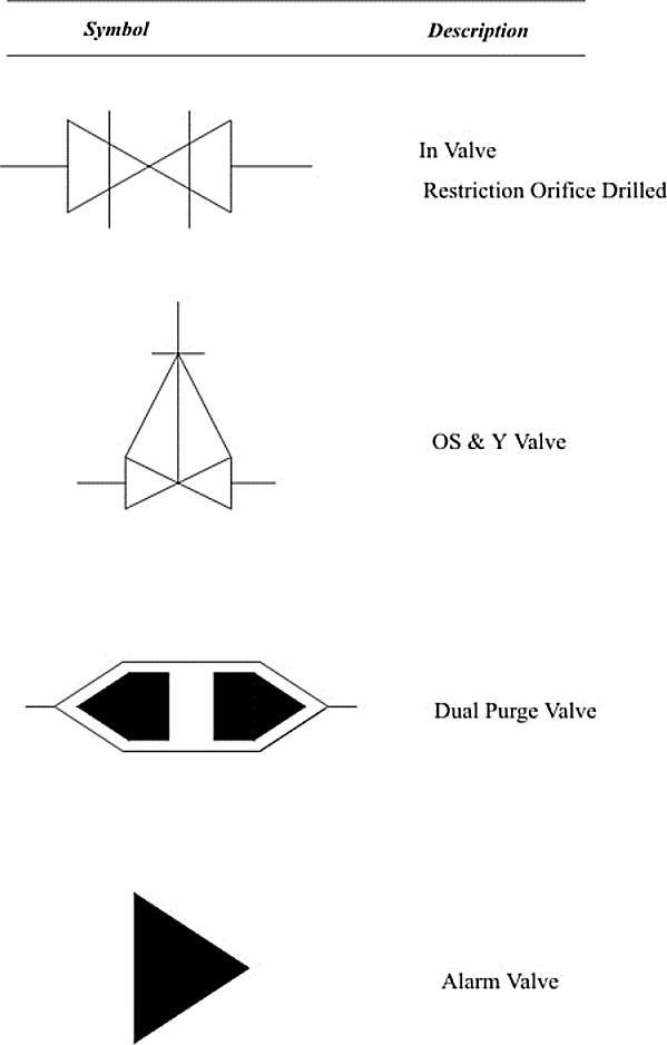


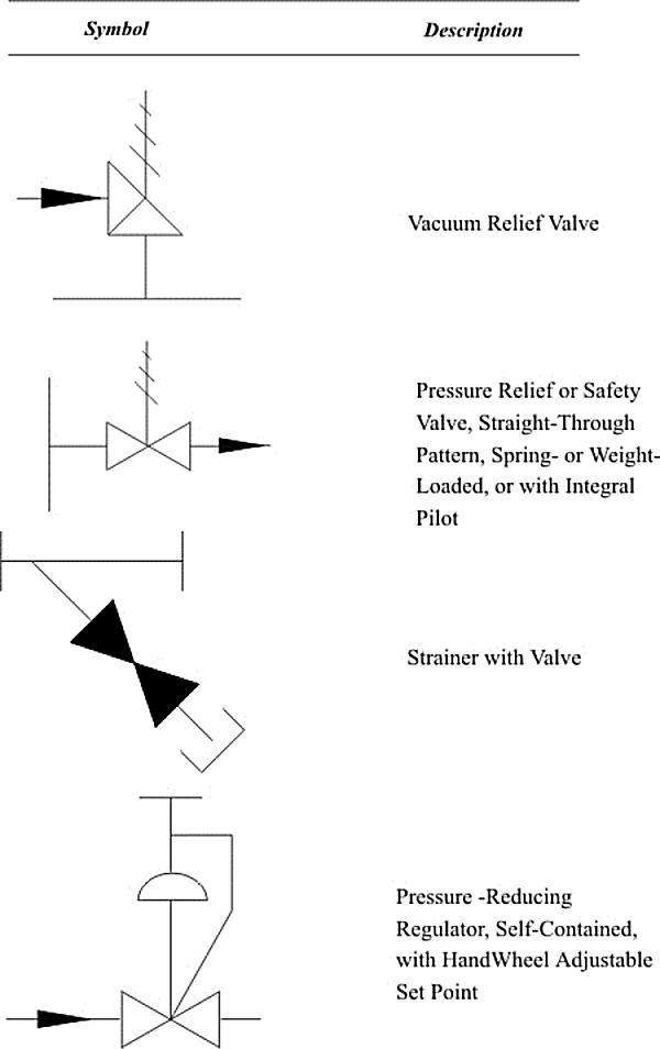


Typical P&ID

Typical process data sheet

Some websites for safety information
The following websites may be of interest for those searching for more information or support for process safety related projects. The list is only a sample of the range of facilities available.
| Subject | Website | Comment |
|---|---|---|
| Chemical Safety | http://www.rose-hulman.edu/Library/www/chemengin_www.h | |
| Safety Standards | http//:www.standards.com.au | |
| Dyadem | http://www.dyadem.com | Canada based PHA consulting. Software products for PHA and risk analysis including Hazops and FMEA. |
| European Process Safety Centre | http://www.epsc.org.uk | Information and publications on process safety. Source of EPSC Guide to Hazop Studies published by I Chem E. |
| EU Directive Information | http://europa.eu.int/comm/environment/seveso/index.htm#1 | EU centre for information on Chemical Accident Preparedness Prevention and Response. Provides details on the implementation and history of Seveso 2 directive. |
| Exida | http://www.exida.com | US Consulting/engineering group. Manuals and study courses for Certified Functional Safety Expert Provides SIL calculation software tools with reliability databases. Informative newsletter. |
| Factory Mutual | fmglobal.com | Safety equipment testing laboratories and insurers. Certification body. |
| Health and Safety Exec.(UK) | http://www.hse.gov.uk/sources/index | Major contributor to occupational safety technologies and practices. Legally appointed body for safety supervision in UK industry. See index for vast range of data sheets, books and guides. |
| HSE Power and Control Newsletter | http://www.hse.gov.uk/dst/sctdir | HSE safety specialists provide informative newsletters. |
| IEC. International Electro-technical Commission | http://www.iec.ch/home | Develops international standards in all areas of electronics, communication, consumer products, safety instrumentation, etc. Bookstore for IEC standards |
| Instrument Society of America | http://www.isa.org | Bookstore for ISA S84.01. Specialist section on safety systems. |
| Jenbul Consultancy | http://www.jenbul.co.uk | Management and leadership of Hazop studies. Risk assessments etc. Site safety management services. |
| OHSA _USA. | http://www.osha-slc.gov http://www.osha.gov/oshastats.gov |
US Dept of Labour, Occupational Safety and health Administration. Vast database of accident reports, regulatory information and accident statistics |
| Simmons Associates | http://www.tony-s.co.uk | UK consultancy for software management and instrumentation safety practices. Downloads of technical briefs on safety subjects. Support on IEC 61508 compliance and documentation. |
| TUV Services in Functional Safety | http://www.Tuv-global.com/sersfsafety | Based in Germany and USA with offices in many countries. Certification laboratories for safety system devices and PLCs. Find list of PES certifications Papers on certification etc Details of TUV Certified Functional Safety Expert qualification/exam. |
| UK Defense Standards | http://www.dstan.mod.uk | Free standards on download. See computer hazops standard. |
| UK Institute of Electrical Engineers. | http://www.iee.org/Policy/Areas/SCC/index.cfm | Safety competency and commitment website. See also competency newsletter. |
| UK Institute of Chemical Engineers | http://www.iche.co.uk | Publications on hazop studies. |
| Oil and Gas ESD | http://www.oilandgas.org | Safety code of practice |
| US Chemical safety board | http://www.csb.org | Accident reporting and evaluation service. Statistics and reports. |
Practical exercises
Items required
- One 600ml bottle (unopened) of Diet Coke (NOTE … other soft drinks are not acceptable)
- Packet of Mint Mentos (NOTE … other brands or flavours are not acceptable)
- One Mocona type coffee jar (with the tight fitting glass plunger)
- Strainer
- Ice (cubes or crushed)
- Several clear glass drinking glasses
- Roll of paper towels (several cloth tea towels would be acceptable)
- Clear, flexible plastic tube (about 1 metre in length)
- Funnel to fit clear, flexible plastic tube
- Cooking oil
- Bucket to collect waste liquids
- Eye-dropper
- Several drinking straws
- Ice cream and container
- Tea bags
- Fresh carrots
- Kitchen knife for carrots
- Table salt
- Digital thermometer (a liquid filled thermometer probably does not have the accuracy or robustness for this job)
- Baking Soda
- White vinegar
- Two Teaspoons
- One electric kettle (preferably with a lid)
Practical Example 1 – Simple physical reaction
Objective – to illustrate a physical reaction
Requirements
- One 600 ml bottle of diet coke
- Packet of Mint Mentos
Procedure
- Go outside
- Place bottle of diet coke in a “safe” location
- Open bottle
- Add mints
- Stand back
The reaction with the mints will be the famous coke-mentos geyser
This illustrates a physical reaction, and the effect of the correct and incorrect “catalyst”. Is the mint a catalyst, a promoter, or a reagent?
Practical Example 2 – Simple chemical reaction
Objective – to illustrate a chemical reaction
Requirements
- 1 clear transparent drinking glass
- Baking soda
- White vinegar
- Tablespoon
Procedure
- Put on eye protection
- Add some baking soda to the glass (approx 2 tablespoons)
- Slowly add vinegar to glass
- Observe reaction
This is a simple chemical reaction.
The reaction is:
NaHCO3 + CH3COOH => CH3COONa + H2O + CO2
Have the Students balance the reaction.
What kind of reaction is this?
Practical Example 3 – Ideal Gas Law
Objective – to illustrate how temperature changes in gases can cause pressure changes in gases.
Requirements
- (set up in advance)
- 1 device to boil water
- Approx 500 ml water
- 1 empty Mocona coffee jar (or any coffee jar with a tight glass plunger top)
Procedure (in advance)
- Boil water
- Check that the plunger lid is not ridiculously tight. Have every delegate check.
- Add about 15 ml of water to jar.
- Seal lids.
- Check that lids are sealed.
Procedure
- Allow jars to cool to room temperature.
- Ask one delegate to apply the exact same force as previously used. The jar cannot be opened.
Explain the ideal gas law. The volume of gas did not change. The moles of gas did not change. The ideal gas constant did not change. The temperature did change, so the pressure therefore must change.
We can calculate the new pressure.
Practical Example Number 4 – Simple heat transfer
Objective – to illustrate that heat flows from high temperature to low temperature.
Requirements
- 1 device to boil water
- Approx 500 ml water
- Ice cubes or crushed ice
- 2 drinking glasses
- Towels
- Strainer
Procedure
- Fill first drinking glass about ½ full of ice. Fill with water.
- Boil some water in the boiling device
- When water has boiled, fill second glass approx ½ full of freshly boiled water. Fill rest of way with cold water from first glass, using the strainer to ensure ice does not pass to second glass
- Refill first drinking glass with water.
- Dry outside of both glasses as best possible.
At this point, we should have one glass that is about 20-25 deg C warmer than ambient air temperature, and one glass that is about 20-25 deg C colder than ambient air temperature.
Now … ask the delegates to try and estimate the temperature of the glasses, but they are not allowed to touch the glasses. They should feel some warmth from the hot water glass, but nothing from the cold water glass.
This is a simple illustration of radiant heat transfer, and shows how heat flows “downhill” from high temperatures to low temperatures.
Practical Example Number 5 – Change in density of boiling fluids
Objective – to illustrate that a boiling fluid has a lower density than a non-boiling fluid
Requirements
- 1 boiling device
Procedure
- Fill boiling device with water. Carefully note level.
- Boil water
- Carefully note top of liquid level when boiling.
Why are they different? We did not add water to the boiling device, and some water was removed in the form of steam, so why was the level of the boiling liquid higher?
Practical Example Number 6 – Pressure of two different density liquids
Objective – to illustrate that a lower density fluid needs a greater height to create the same pressure gradient as a higher density fluid
Requirements
- Cooking oil
- Clear, flexible plastic tube
- Funnel to fit clear, flexible plastic tube
- Water
- Bucket (to collect waste liquid)
Procedure
- Ask two delegates to hold the tube vertically so there are no kinks
- Using the funnel, add some water to the tube. Observe the height on one side, and compare to the height on the other side – they should be identical
- Using the funnel, add some cooking oil to the tube. Observe the height on one side, and compare to the height on the other side – they should be different
Why are they different? They are different because the density is different.
Practical Example Number 7 – Natural convection evaporation
Objective – to illustrate how evaporation of a fluid below its boiling point can occur, and how it cools
Requirements
- Water
Procedure
- Ask each delegate to place a drop of water onto the back of their hand
- Ask each delegate to spread the water around the back of their hand
- Ask the delegates to blow on the back of their hand
Why did their hands get cold? The water was at room temperature, the hand was at room temperature, and water does not boil until it reaches 100 deg C.
Practical Example Number 8 – Sublimation
Objective – to illustrate how some components can go from vapour to solid without making a liquid.
Requirements
- Ice Cream container taken directly from the freezer
- Towel
Procedure
- Wipe container to ensure it is dry
- Have the delegates observe the outside of the container
- Observe frost forming on the outside
- Open the ice cream container
- In a few moments, the outside of the container that does not have ice cream touching it will be liquid instead of frost
The frost is always dry – it goes from vapour to solid.
Practical Example Number 9 – Simple mass transfer
Objective – to illustrate how a concentration driving force works, and to see the effect of temperature
Requirements
- 2 clear, sturdy drinking glasses (tumblers)
- 2 teabags
Procedure
- Make two “cups of tea” but in one, be very careful to not agitate anything. With time, the unstirred tea will tend to collect in one spot, and you will be able to see clear water, and tea separately in the glass
- While the tea is being leached from the teabags, take the remaining two glasses.
- Fill one with hot water
- Fill the other with either cold or room temperature water
- Repeat without agitation with the two glasses of different temperature
- The tea should move quicker through the hot water.
Both practicals illustrate conduction and convection mass transfer, and the effect of temperature on mass transfer.
Practical Example Number 10 – Density
Objective – to illustrate how a density can change buoyancy
Requirements
- 1 clear drinking glass per delegate
- Room temperature water
- Fresh carrots
- Knife to cut the carrots
- Table salt
Procedure
- Fill each glass with water
- Add a thick slice of carrot to each glass. The carrot should sink.
What is the density of carrot compared to the density of water?
- Now, slowly add salt to the water, until the carrot starts to float
What is the density of carrot compared to the density of salt water?
This illustrates the principle of many hydro-metallurgy processes, using changing density to progressively separate and purify our component.
Practical Example Number 11 – Endothermic reaction
Objective – to illustrate how a chemical reaction can lower temperature
Requirements
- 1 clear drinking glass
- Room temperature white vinegar
- Baking soda
- Digital thermometer
Procedure
- Place thermometer in glass
- Add 20-25 ml of white vinegar. If this does not cover the thermometer, add more vinegar in increments of 20-25 ml until covered
- Record temperature
- Add one teaspoon of baking soda per 20-25 ml of vinegar.
- Note the reaction (including bubbling)
- Watch temperature, and record lowest temperature.
The reaction consumes heat – it draws heat from the atmosphere – that is why the temperature dropped.

Professional Certificate of Competency in Advanced TCP/IP-Based Industrial Networking
Designed for engineers and technicians who need practical knowledge in…Read more
Professional Certificate of Competency in Allen Bradley Controllogix / Logix5000 PLC Platforms
Designed for engineers and technicians who need practical knowledge in…Read more
Professional Certificate of Competency in Arc Flash Protection
Designed for engineers and technicians who work in the electrical…Read more
Professional Certificate of Competency in Chemical Engineering and Plant Design
Designed for engineers and technicians who need practical knowledge in…Read more
Professional Certificate of Competency in Circuit Breakers, Switchgear and Power Transformers
Designed for engineers and technicians who need practical knowledge regarding…Read more
Professional Certificate of Competency in Control Valve Sizing, Selection and Maintenance
Designed for engineers and technicians who need a solid understanding…Read more
Professional Certificate of Competency in Electrical Power System Fundamentals for Non Electrical Engineers
Designed for engineers and technicians who need to understand the…Read more
Professional Certificate of Competency in Electrical Power System Protection
Designed for engineers and technicians who need practical skills and…Read more")
Professional Certificate of Competency in Electrical Wiring Standards: AS/NZS 3000:2018 (Australia and New Zealand Only)
This professional development course is designed for engineers and technicians…Read more
Professional Certificate of Competency in Fundamental E & I Engineering for Oil and Gas Facilities
Designed for engineers and technicians who need to update their…Read more
Professional Certificate of Competency in Gas Turbine Engineering
Designed for engineers and technicians who need practical skills in…Read more
Professional Certificate of Competency in Hazardous Areas and Intrinsic Safety For Engineers and Technicians
Designed for engineers and technicians who need to understand the…Read more")
Professional Certificate of Competency in Heating, Ventilation and Air-Conditioning (HVAC)
Designed for engineers and technicians from a wide range of…Read more
Professional Certificate of Competency in IEC 61850 Based Substation Automation
Designed for engineers and technicians who need to understand the…Read more
Professional Certificate of Competency in Industrial Data Communications
Designed for engineers and technicians who need to understand how…Read more
Professional Certificate of Competency in Instrumentation, Automation and Process Control
Designed for engineers and technicians who need to gain practical…Read more
Professional Certificate of Competency in Machine Learning and Artificial Intelligence
This professional development course is designed for engineers and technicians…Read more
Professional Certificate of Competency in Mechanical Engineering
This professional development course is designed for engineers and technicians…Read more
Professional Certificate of Competency in Onshore and Offshore Pipeline Systems
Designed for engineers and technicians who need to gain an…Read more
Professional Certificate of Competency in Power Distribution
designed for engineers and technicians who need to gain a…Read more
Professional Certificate of Competency in Practical Machine Learning Using Python for Engineers and Technicians
Designed to use Python Programming to work with machine learning…Read more
Professional Certificate of Competency in Practical Python for Engineers and Technicians
Designed for engineers and technicians who need to understand the…Read more & SCADA Systems")
Professional Certificate of Competency in Programmable Logic Controllers (PLCs) & SCADA Systems
Designed for engineers and technicians who need to get practical…Read more
Professional Certificate of Competency in Project Management for Engineers & Technicians
This professional development course is designed for engineers and technicians…Read more
Professional Certificate of Competency in Safety Instrumentation Systems for Process Industries
Professional development course designed for engineers and technicians who want…Read more
Professional Certificate of Competency in Sewage and Effluent Treatment Technologies
Designed for engineers and technicians who need practical skills and…Read more
Professional Certificate of Competency in Structural Design for Non Structural Engineers
Professional development course designed for engineers and technicians who need…Read more")
Professional Certificate of Competency in Substation Design (Main Equipment)
Professional development course is designed for engineers and technicians who…Read more")
Professional Certificate of Competency in Substation Design (Control, Protection and Facility Planning)
Designed for engineers and technicians who need to gain practical…Read more
Professional Certificate of Competency in the Fundamentals of Process Plant Layout & Piping Design
Professional development course is designed for engineers and technicians who…Read more
Professional Certificate of Competency in Practical Mechanical Sealing
This professional development course is designed for engineers and technicians…Read more
Professional Certificate of Competency in Road Construction
This professional development course is designed for engineers and technicians…Read more
Professional Certificate of Competency in Specification and Technical Writing
Master the art of writing clear, accurate, and professional technical…Read more
Professional Certificate of Competency in Hydraulics and Pneumatics
Overview of all aspects related to the construction, design, operation,…Read more
Professional Certificate of Competency in Big Data and Analytics in Electricity Grids
This course explores the use of big data & data…Read more
Professional Certificate of Competency in Renewable Energy Systems
This course covers various renewable energy systems that are popular…Read more
Professional Certificate of Competency in Smart Grids
A smart grid is an electricity network that uses digital…Read more
Professional Certificate of Competency in Hydrogen Energy – Production, Delivery, Storage and Use
Hydrogen energy short course designed for engineers and professionals interested…Read more")
Professional Certificate of Competency in Building Information Modelling (BIM)
This professional development course is covering practical aspects of using…Read more
Professional Certificate of Competency in Industrial Internet of Things
Internet of Things (IoT) is the most sort after technology…Read more