This manual will enable you to reduce expensive downtime on your plant and equipment by following the correct application and selection of lightning and surge protection devices.
Designed for engineers and technicians who need to understand the basics of electrical engineering. The course mainly focusses on earthing, bonding, lightning, and surge protection. Learn more
IDC Technologies Pty Ltd
PO Box 1093, West Perth, Western Australia 6872
Offices in Australia, New Zealand, Singapore, United Kingdom, Ireland, Malaysia, Poland, United States of America, Canada, South Africa and India
All rights to this publication, associated software and workshop are reserved. No part of this publication may be reproduced, stored in a retrieval system or transmitted in any form or by any means electronic, mechanical, photocopying, recording or otherwise without the prior written permission of the publisher. All enquiries should be made to the publisher at the address above.
Disclaimer
Whilst all reasonable care has been taken to ensure that the descriptions, opinions, programs, listings, software and diagrams are accurate and workable, IDC Technologies do not accept any legal responsibility or liability to any person, organization or other entity for any direct loss, consequential loss or damage, however caused, that may be suffered as a result of the use of this publication or the associated workshop and software.
In case of any uncertainty, we recommend that you contact IDC Technologies for clarification or assistance.
Trademarks
All logos and trademarks belong to, and are copyrighted to, their companies respectively.
Acknowledgements
IDC Technologies expresses its sincere thanks to all those engineers and technicians on our training workshops who freely made available their expertise in preparing this manual.
ACKNOWLEDGEMENTS
The following resources have been made use of in preparing this manual and are duly acknowledged.
Standards and Codes of Practice
AS1768-2007 Lightning Protection
IEEE 80:2000 IEEE Guide for Safety in Substation Grounding
IEEE 1100:2005 IEEE Recommended Practice for Powering and Grounding of Electronic Equipment
IEEE 142:2007 (Green Book) IEEE Recommended Practice on Grounding of Industrial and Commercial Power Systems
IEEE C62.41-1991 IEEE Recommended Practice on Surge Voltages connected to Low Voltage AC Power Circuits
ESKOM Distribution Standard Part-2 Earthing (SCSASAAL9-July 1999)
IEC/TR 61400-24 Wind turbine generator systems – Part 24: Lightning protection (Technical Report)
Technical Papers, Reports and Bulletins
Technical paper ‘Safe Coordination between power and communication surge protection’ by Alain Rousseau and Alistair Hunt
Technical Paper ‘Active Lightning protection systems and a means of calculating the protective area’ by A.J. Surtees
Technical paper ‘A method of identifying the lightning strike location on a structure’ by Hartono and Robiah (ICEMC ‘95 at Kuala Lumpur)
NOAA Technical Memorandum NWS SR-193 on Lightning Fatalities, Injuries, And Damage Reports In The United States From 1959-1994
Technical Paper The U.S. National Lightning Detection Network and Applications of Cloud-to-Ground Lightning Data by Electric Power Utilities by Cummins et al. from the IEEE Transactions On Electromagnetic Compatibility, Nov 1998
Technical Paper ‘Lightning Mapping System’ by C. Lennon and L. Maier of National Aeronautics And Space Administration
Technical Paper A Critical Review of Non conventional Approaches to Lightning Protection’ by M.A. Uman and V.A. Rakov in the American Meteorological Society publication (Dec 2002)
Technical Paper ‘Principles Of Lightning Protection For Telecommunications Facilities’ by A.J. Surtees (http://www.powerquality.com/art0047/art1.html)
Report Of The Third-Party Independent Evaluation Panel On The Early Streamer Emission/Lightning Rods Lightning Protection Technology by Bryan et al (A recommendation made to NFPA Standards Council.
National Renewable Energy Laboratory, Wind Turbine Lightning Protection Project Report 1999—2001
Technical paper ‘Lightning protection for wind turbine blades and bearings’ by Ian Cotton et. al,
Technical paper ‘Lightning Protection Optimization for Large Wind Turbines with Method-of-Moments’ by Florian Krug, Ralph Teichmann et. al.
Product Guides and Application notes of various Manufacturers (ERICO Inc., Furse, Lightning Master Corporation, MTL technologies)
Contents
Acknowledgments i
1 Overview 1
1.1 Lightning and its effects 1
1.2 Lightning protection system for a building or structure 2
1.3 Lightning detection and warning systems 4
1.4 Role of grounding in lightning protection systems 4
1.5 Bonding of grounding systems and metallic services 5
1.6 Surge protection 5
1.7 Maintenance of lightning protection systems 6
1.8 Additional information 6
2 Lightning physics, effects and risk assessment 7
2.1 The Physics of Lightning 8
2.2 Incidence of lightning strikes 13
2.3 Probability of a lightning strike 18
2.4 Effect of lightning strike on objects on the ground 20
2.5 Indirect effects of lightning 22
2.6 Effect of lightning strike on electrical installations 24
2.7 Assessment of lightning risk 24
2.8 Summary 28
3 Lightning safety 29
3.1 Human safety aspects 29
3.2 Risk of lightning strike – statistics 29
3.3 Personnel safety measures against lightning strike 31
3.4 Importance of lightning detection 33
3.5 National Lightning Detection Network (NLDN)TM – an overview 34
3.6 Sensors for detection in areas not covered by LDN 36
3.7 Summary 40
4 Lightning protection of structures 41
4.1 Basics of lightning protection of structures 41
4.2 Lightning protection levels 42
4.3 Lightning protection system design approach 43
4.4 Main components of a lightning protection system 54
4.5 Materials used in lightning protection systems 64
4.6 Dependence of protection requirements on type of structure 59
4.7 Side flash 60
4.8 Alternative hypothesis for protection adequacy 62
4.9 Non-conventional lightning protection systems 64
4.10 Summary 67
5 Lightning protection of electrical lines and substations 69
5.1 Effect of lightning strike on electrical installations 69
5.2 Protection of electrical lines 69
5.3 Protection of electrical substations 72
5.4 Summary 74
6 Principles of grounding and bonding as applicable to lightning protection systems 75
6.1 Objectives of grounding 75
6.2 Electric shock 76
6.3 Objectives of bonding 80
6.4 Equipotential bonding 82
6.5 Routing of grounding conductors 84
6.6 Ground electrodes 86
6.7 Soil resistance 86
6.8 Measurement of soil resistivity 89
6.9 Resistance of a single rod electrode 91
6.10 Current carrying capacity of an electrode 93
6.11 Use of multiple ground rods in parallel 94
6.12 Measurement of ground resistance of an electrode 94
6.13 Concrete encased electrodes 96
6.14 Chemical electrodes 98
6.15 Corrosion problems in electrical grounding systems 100
6.16 Maintenance of grounding system 101
6.17 Summary 101
7 Surge protection of equipment – Part I 103
7.1 Introduction 103
7.2 What is a surge? 103
7.3 Principle of surge protection 106
7.4 Surge protection devices 107
7.5 Graded surge protection 111
7.6 Selection of suitable device for surge protection 115
7.7 Positioning and selection of lightning/surge arrestor 116
7.8 A practical view of surge protection for sensitive equipment 119
7.9 Mitigation of surges 122
7.10 Codes on surge protection 125
7.11 Summary 126
8 Surge protection of equipment – Part II 129
8.1 Introduction 129
8.2 SPD for signal applications 129
8.3 Surge protection of instrumentation systems 131
8.4 General principle of surge protection of transmitters 132
8.5 Surge protection of transmitters at the field end 133
8.6 Comprehensive loop protection 134
8.7 SPDs for other types of sensors 135
8.8 Protection of telemetry systems 136
8.9 Protection of data communication systems 137
8.10 SPD for hazardous applications 138
8.11 Grounding of intrinsically safe circuits 139
8.12 Summary 140
9 Maintenance of lightning protection systems 143
9.1 Introduction 143
9.2 Need for maintenance 143
9.3 Maintenance activities 144
9.4 Summary 145
Appendix-A Risk Assessment approach recommended in AS:1768 147
Appendix-B Lightning protection of wind turbines 155
Appendix-C Lightning protection of marine equipment 175
Appendix-D Electrical noise and mitigation 181
Appendix-E Exercises 215
Appendix-F Case Study 253
In this chapter, we will introduce the phenomenon of lightning and the means of protecting buildings and structures from being damaged by lightning strikes and the importance of the role of grounding and bonding. We will also touch upon lightning detection and warning systems. We will also introduce the topic of surge protection of sensitive equipment. All these concepts will be explained in detail in the chapters that follow.
Learning objectives
This chapter dwells upon the following topics:
Lightning and its effects on facilities and equipment
Approach for protecting buildings and structures from lightning strikes
Detection and warning systems
Role of grounding and bonding in lightning protection
Surge protection of electrical equipment (power, communication and control)
Need for maintenance of lightning protection components
1.1 Lightning and its effects
Lightning is the sudden draining of electrical charge built up in low cloud systems. It may involve another cloud system (which is not of much interest to us in this course) or ground (which is). The flow of charge creates a steep fronted current waveform lasting for several tens of microseconds. A direct lightning strike on a human body or livestock can result in death or serious injury. Lightning can cause destruction of a living organism, such as a tree. It can damage building parts through which the lightning surge is conducted to the ground. It can even place personnel within a building at risk because of very high potential differences between different parts of a building that carry the lightning surge. Even the flow of lightning surges in the ground can cause electrocution due to high potential differences between different points in the soil carrying the surge currents. Lightning strikes on electrical installations (which include overhead conductors of power and communication lines) can cause current and voltage surges. A nearby strike to the ground can cause such problems by coupling into electrical circuits. A surge may consist of a single spike or multiple diminishing spikes and unless properly protected against, can cause failure of insulation in electrical wiring or devices due to excessive voltage. A surge traveling through electrical power supply network can damage sensitive electronic equipment. A proper understanding of the mechanism of lightning and its effects is, therefore, essential for planning protection against lightning strikes so that no damage is caused to personnel, buildings and electrical installations.
Lightning is one of the most widely studied and documented of all natural phenomena. Over the years a lot of research has been done worldwide and several publications as well as national and international standards have evolved. These give us a good insight into this phenomenon.
Some of these standards are:
AS 1768:2007 Australian Standard on Lightning protection
ANSI/NFPA 780 National Lightning protection code
IEC 61024 Lightning Protection of structures
IEC 61312 Protection against lightning electromagnetic impulse
IEC 61662 Assessment of risk due to lightning
IEC 61663 Lightning protection of telecommunication lines
IEEE 142:2007 IEEE Green Book (Chapter-3)
IEEE 487-2000 Protection of Wire-Line Communication Facilities Serving Electric Power Stations
While it is difficult to predict the behavior of lightning with exactitude, it is possible to provide a high level of safeguard against damages, injuries and loss of life due to lightning. The following are some of the ways of protecting personnel and installations against lightning and related ill effects:
Lightning warning systems to warn personnel who are engaged in outdoor activities about impending lightning activity to enable them to take shelter
Lightning protection systems for structures as per relevant codes
Quality grounding and bonding
Surge arrestors on power circuits
Multi-level graded protection of signal paths using Surge Protective Devices (SPD)
Periodic maintenance of lightning protection systems to ensure integrity of conducting paths.
We will discuss in this course the phenomenon of lightning, its effects and prevention of damages due to lightning strikes (also called lightning flashes).
1.2 Lightning protection system for a building or structure
A lightning protection system to be provided for a building or any other structure is based on the perceived risk of a lightning strike and the damage it may cause. The risk is, in turn, related to the extent of lightning (or thunderstorm) activity in the region where the facility is situated. Many countries have collected data on thunderstorms in their territories, which are published in the form of Isoceraunic maps for different world regions in different national and international standards. Figure 1.1 shows the distribution of lightning activity on a worldwide basis. The activity is expressed in terms of Flashes/Sq. km/Year. Note that the activity in arid regions is much lower than in regions with high rainfall. Areas with very little occurrence of thunderstorms are naturally at a much lower risk. Large continental regions close to the equator are observed to have a high level of lightning activity. Another observation is the lower incidence of lightning in oceans. The lightning activity increases as we approach the landmass.
Figure 1.1 Worldwide lightning activity distribution
Other factors such as the type of surroundings, height of the structure, type or value of contents in a building, degree of human presence, etc., are also of importance in deciding the extent of risk due to lightning and play a major role in deciding upon the necessity of providing lightning protection (or otherwise) for each specific case. Different national standards have evolved specific methods for risk assessment. We will discuss typical assessment methods in detail later in this course.
Once the need for providing lightning protection is assessed by these methods, the next step is to design a suitable protection system. It should be recognized that no system can guarantee 100% protection against all incidents of lightning. The severity of the lightning expressed in terms of the current flow varies and to ensure protection against all cases is simply not possible. The most probable values are considered in the design of lightning protection systems in order to make them cost effective and at the same time provide reasonable protection against most cases of lightning strikes.
Lightning protection systems have evolved over the years, from the simple Franklin Rod, followed by the Faraday cage method, to the modern, non-conventional lightning protection systems. A number of products are available in the market to ensure reliable protection of facilities against direct lightning strikes. Some of them have active lightning attraction components, which claim to focus the lightning discharges on themselves instead of other vulnerable portions of the facility that is being protected. Others attempt to suppress the formation of a lightning strike from happening. These claims are not validated properly and their scientific basis is open to debate. We will, however, review them briefly in the later chapters of this document.
Methods of computing the effectiveness of protection have also been under evolution, starting from the Cone of Protection type of analysis, to the Rolling Sphere Method, to the computations based on Collection Volumes. Many organizations such as the Electric Power Research Institute (EPRI), USA and the Lightning Safety Institute, as well as manufacturers of lightning protection hardware offer design services using computer applications which help in assessing the lightning risk and designing the most appropriate protection system. We will demonstrate a typical application as a part of the hands-on session in this course.
We will also discuss in detail the effects of lightning on electrical lines and outdoor installations and how these facilities can be protected against the damaging effects of strikes using the above-discussed principles.
1.3 Lightning detection and warning systems
While Isoceraunic maps are useful in obtaining a fair idea about the frequency of thunderstorms in a given area, they do not really help in understanding the actual number of cloud to ground lightning strokes or the severity of lightning discharges, both of which have a bearing on the design of lightning protection systems. The United States of America has addressed this issue with the installation of a network of lightning sensors throughout the geographical area of the country and by linking them on a real time basis to a central facility. This system communicates the presence of lightning activity in the area covered by each sensor, and the data of each discharge, to the central monitoring facility using satellite links. This facility immediately analyzes the data and issues appropriate warnings to local agencies for preventive measures. We will review the details of this network in a later chapter.
For areas where such a network does not exist, as well as for facilities handling highly hazardous materials (which may not want to rely on an external agency for warnings), individual localized lightning warning products can be deployed. Such products are also useful in outdoor facilities such as golf courses, wind farms etc., to indicate the approach of a thunderstorm so that people present in these sites can be warned to take shelter in safe locations. We will discuss a couple of typical systems later in this course.
1.4 Role of grounding in lightning protection systems
As noted in an earlier section, grounding plays a very important role in the protection of buildings and equipment against direct lightning strikes as well as surges from indirect strikes. In the case of direct strikes, a low impedance path from the lightning protection conductor to the ground is essential to keep the inevitable voltage-rise within safe limits, when currents of large magnitudes are conducted by the lightning protection system. Note the use of the term impedance in preference to resistance here. While the normal power system ground is designed primarily to provide a low resistance path to ground, in the case of grounding systems of lightning/surge protection systems, it is the impedance which is of importance. As we shall see later, a surge gives rise to voltage and current pulses having extremely fast rise times. Any inductance in the grounding circuit obstructs the flow of surge currents and produces a voltage drop. This drop is a function of the inductance and the rate of rise of the current. Remember that even a piece of wire has its own self-inductance, which is sufficient to cause an appreciable voltage drop while conducting a lightning surge if the length becomes excessive. Thus the grounding conductors of a lightning protection system (including the ground connections of surge protection devices) must be as short as possible and without any avoidable bends.
Conduction path to lightning can also be provided using the building’s structural members. In the case of concrete buildings, the steel reinforcement (re-bars) can provide a low impedance ground path.
The availability of a good, low-resistance (and low impedance) ground electrode system is also a matter of importance. The voltage rise of a facility is to be computed with reference to the true ground (the general earth mass) and electrode resistance thus becomes an important factor as the voltage drop across this resistance contributes to the potential rise. We will discuss in detail the principles of grounding electrodes, the effect of soil resistivity on ground electrode resistance and methods of obtaining lower ground resistance under difficult soil conditions (by the use of chemical electrodes and soil enhancement). Most vendors of integrated lightning protection systems include the required materials for ensuring low ground electrode resistance to facilitate proper operation of their protective systems.
We will briefly discuss electric shock and what causes it. The principles of electric shock and the related topics of ground potential rise, step potential and touch potential are applicable not only to electrical power systems but also to lightning protection installations.
1.5 Bonding of grounding systems and metallic services
Another important issue in protection of sensitive electrical equipment against damage by lightning-induced surges is the relative potential difference that can be caused during a lightning discharge through the protection system. To eliminate or at least minimize such potential difference, it is necessary to bond together the different grounding systems as well as other metallic service lines in a facility, so as to achieve an equipotential plane. Many a failure of sensitive electronic and communication equipment is due to the oversight of designers of these individual systems in recognizing the need for such bonding. A good designer will ensure integration of these systems properly so as to avoid destructive potentials from appearing between the internal parts of sensitive devices.
1.6 Surge protection
One of the major effects of lightning strike on electrical and electronic equipment is a high voltage surge. A surge is caused by the lightning discharge when the associated current tries to find a path to ground. A surge need not be due to a direct strike alone but can happen due to a strike on a nearby structure. In this event, a surge can be transmitted into an adjacent electrical system (which in this context includes communication or control systems) by various means.
These are:
Galvanic (direct Electrical Contact)
Electrostatic coupling
Electromagnetic Induction
Radio Frequency interference (RFI)
The type of protection to be provided at different points in the electrical system is based on the surge voltage/current values that the equipment is likely to be subjected to. For example, the highest exposure to surges happens in the equipment connected to an external power system. The surge current pulse reduces in magnitude with correspondingly lower energy levels as we move from the power inlet equipment to the main distribution circuits, then to the branch distribution and finally to power supplies of sensitive equipment. This is mainly because of the fact that the inductance of the conductors has an attenuating effect on the surge pulse. Even a short length of conductor may present substantial impedance because of the fact that the very steep wave front of a surge has the same effect as a current of very high frequency.
This means that equipment connected to the external power supply system needs to have a high impulse withstand rating while equipment further down the system can be rated progressively lower. Also, the devices used for surge protection must be suitably graded depending on the level of surge energy expected at the points of the electrical system where they are installed.
Several types of devices are available for protection of electrical equipment from the damaging effects of surges. These components are commonly known as Lightning arrestors (used to protect large electrical equipment such as transformers or switchgear from being damaged by surges) or Surge Protection Devices (SPD), a term used mainly in the context of sensitive equipment. Transient Voltage Surge Suppressor (TVSS) is another name for an SPD, an older term mostly used in earlier references. All these devices function by providing a low-impedance ground path and safely diverting the surge currents (and thereby the damaging energy of a surge) to ground – away from the sensitive equipment which they protect. The characteristic of these devices is such that they do not come into play during normal system conditions but act only when the voltage of the system exceeds certain threshold values. We will discuss these systems and devices in detail later.
1.7 Maintenance of lightning protection systems
Lightning protection systems operate under difficult conditions and are constantly exposed to weather. Also, the grounding components are usually buried in soil and are subject to corrosion due to galvanic action of stray currents as well as the action of chemical substances in the soil. Unless these components are periodically inspected and the defects attended to, the system may fail when subjected to lightning surges and may endanger life and property. We will discuss the measures to be instituted for periodic inspection and checks on various system components in the concluding chapter.
1.8 Additional information
We will discuss the above concepts in detail in the chapters that follow this overview. A few appendices have also been included for information on related topics. The first of these appendices illustrates the principles of lightning risk assessment as suggested by the Australian Standard AS 1768:2007. Others include lightning protection measures for special structures such as a Wind turbine generator and marine installations and the measures to be taken for mitigation of electrical noise (which can be caused by the Radio Frequency Interference from lightning activity).
We will discuss in this chapter the physics relating to the formation of atmospheric charges and the resulting lightning discharges. We will also briefly touch upon the problems a lightning strike can cause to natural objects and man-made structures. We will discuss in detail the risk assessment approach to be adopted while deciding upon the need for lightning protection of a given structure or facility.
Learning objectives
Definitions of terms related to lightning
The physics of lightning, its characteristics and strike probability
Effects of lightning strike
Lightning risk assessment procedure
Definition of terms used
Lightning flash (or Lightning discharge): An electrical discharge in the atmosphere involving one or more electrically charged regions, most commonly in a cumulonimbus cloud, taking either of the following forms:
Ground flash (or Ground discharge): A lightning flash in which at least one discharge channel reaches the ground. Cloud flash: A lightning flash in which the discharge channels do not reach the earth.
Lightning flash density: The number of lightning flashes of the specified type occurring on or over unit area in unit time. This is commonly expressed as flashes per square kilometer per year. The ground flash density is the number of ground flashes per unit area and per unit time, preferably expressed as a long-term average value.
Lightning protection system: A system of conductors and other components used to reduce the injurious and damaging effects of lightning.
Lightning strike: A term used to describe the lightning flash when the attention is centered on the effects of the flash at the attachment point (see definition below), rather than on the complete lightning discharge.
Lightning strike attachment point: The point on the ground or on a structure where the lower end of the lightning discharge channel connects with the ground or structure.
Lightning stroke: A term used to describe an individual current impulse in a complete ground flash.
Thunderday: A calendar day during which thunder is heard at a given location. The international definition of lightning activity is given as the number of thunderdays per year (also called ‘isoceraunic level or ceraunic level’).
Zone of protection: The portion of space within which an object or structure is considered to be protected by a lightning protection system.
2.1 The Physics of Lightning
Lightning is the sudden draining of charge built up in cloud systems. Lightning may occur between two cloud systems, within a single cloud system or between a cloud system and ground. Most lightning is within the cloud or between cloud systems. Only about 15% are cloud-to-ground discharges, also called ground flashes, these being responsible for the bulk of the damaging effects of lightning. Cloud-to-cloud discharges can generate radio interference, often heard as clicks and bangs from nearby storms, or whistles and howls from storms on the other side of the planet. The discharges to ground are far more destructive than the discharge between clouds. This is because a direct lightning strike may involve a living being or other objects which are subjected to extremely high-magnitude short-duration current pulses that happen during the sudden transfer of charge from the cloud to the ground.
We will now discuss how such a build up of electrical charge occurs in cloud systems. Updraughts and downdraughts of air are fairly common events experienced by most of us in the form of turbulence when we fly in an aircraft. Such movements of air may be generated by heat coming from hillsides in full sun, by cold air masses pushing underneath warmer air in a frontal weather system or simply by the deflection of air currents by high mountain systems. We know that the temperature of the atmosphere falls as we rise higher than ground level, at the rate of approximately 60 C for every km above mean sea level. As the air rises, it progressively cools and forms a cloud consisting of water droplets and, at greater heights (where the temperatures are extremely low, being around –40 to –60 Deg C), consisting of ice crystals. A ‘thunder cloud’ is a system of this type in which the air velocities are much greater than normal.
Figure 2.1 shows the wind, temperature and ice/water distribution in a thundercloud. The violent updraughts and downdraughts within the cloud system can generate static electricity charges running to several kV in magnitude. Though the exact mechanism of charge separation is not clear, observations indicate that the ice particles in the top portion of the cloud are positively charged whereas the heavier water particles in the bottom portion of the cloud carry a negative charge.
Note from the figure that lightning flashes occur between clouds (inter-cloud), within a cloud system (intra-cloud) or between a cloud system and ground. The occurrence of a lightning flash to ground happens when a build up of charge takes place in a cloud system close to the ground. This charge is usually of the order of several million volts and usually of negative polarity at the bottom. The flow of charge between the cloud system and ground during a lightning flash creates a steep fronted current waveform lasting for several tens of microseconds. The flow is more usually that of negative charge though at times it may involve positive charge flow too. About 95% of ground flashes belong to this type (flow of negative charge). When positive strokes do occur, they are usually at the end of the active life of a particular thundercloud and a single stroke may discharge the whole of the upper positive cloud charge center in a stroke of exceptional severity. The statistically less frequent positive lightning flash usually consists of a single stroke having average and maximum peak amplitudes that are significantly higher than negative lightning strokes and is accompanied by continuing current with a total duration that can be as long as one to two seconds.
Figure 2.1 Charge build up within a cloud system
Figure 2.2 shows the charge separation in a cloud and the corresponding induced charges in the ground. The movement of clouds causes a corresponding movement of positive charges on the ground. This is observable as a corresponding current flow in metallic pathways such as pipelines on the ground.
Figure 2.2 Charge separation in a cloud and induced charges in the ground
The high electrical field between the cloud and ground (which may be as high as 20 kV/m immediately below the thundercloud charge centre) causes ionization of the air and creates a conducting path. The first stroke of a ground flash is normally preceded by a downward-progressing low-current leader discharge, which commences in the negatively charged region and progresses towards the earth, depositing negative charge in the air surrounding the channel. The leader proceeds in steps of 20 to 30 meters towards the ground, each step forming further ionization for the subsequent step. When the lower end of the leader is roughly 100 m from the ground, upward electrical discharges (streamers) are initiated from sharp objects on the ground, such as the tips of radio masts and flagpoles and propagate towards the leader channel. These objects are essentially conductors short-circuiting part of the vertical field and hence producing an intense field concentration at the tip. Natural objects can also promote point discharges, particularly in mountainous areas where physical elevation further intensifies the field. Several streamers may start, but usually only one is successful in reaching the downward leader. The high current phase (return stroke) commences at the moment the upward moving streamer meets the downward leader. The position in space of the lower portion of the lightning channel is, therefore, determined by the path of the successful streamer, i.e. the one which succeeded in reaching the downward leader. See Figure 2.3 (a) to (d) below for the progression of a typical lightning stroke.
Figure 2.3 Lightning stroke initiation
The lightning flash discharging along the ionized channel causes a very high peak of current amounting to several kilo amperes and dissipates its energy in the form of heat (temperatures up to 20 000ºC for a few microseconds), sound and electromagnetic waves (light, magnetic fields and radio waves).
A ground strike consists of a sequence of one or more high amplitude, short duration current pulses. The initial leader stroke and main return stroke are generally followed by subsequent leaders and return strokes in rapid succession. Up to 42 separate strokes have been recorded as forming one discharge. Stroke spacing is in tens of milliseconds and, physically, each follows the initial leader track unless heavy winds or other disturbances move the channel. In some ground-strokes, low amplitude, long duration currents (sometimes termed continuing currents) flow between the strokes or after a sequence of strokes. The currents are unidirectional and are usually negative, i.e. a negative charge is injected into the object struck. For all practical purposes, the stroke can be considered to be generated by a current source whose wave shape and magnitude are unaffected by the characteristics of the ground termination.
Some of the parameters of a lightning stroke that are of interest to us are:
Peak current (I) usually expressed in Kilo Amps
Rate of rise of current (dI/dt) in Kilo Amps per micro-second
Time to Crest (TCR) in micro-seconds
Time to fall to half of peak value (Th)
As the rate of rise is not uniform throughout, this value is further expressed as dI/dt (Max), dI/dt (10%/90%) and dI/dt (30%/90%). dI/dt (Max) is the maximum value of slope in the rise curve, dI/dt (10%/90%) is the average slope between 10% of peak current and 90% of peak current and so on. Figure 2.4 shows a typical lightning waveform.
Figure 2.4 Typical waveform of lightning
As we saw earlier, a lightning discharge consists of multiple strokes, each represented by a current pulse or wave. The first current wave has a relatively lower dI/dt but a higher magnitude, followed possibly by several more (on an average 3) of a much higher dI/dt but a lower peak current. Figure 2.5 shows a typical lightning discharge.
Figure 2.5 A typical lightning discharge with multiple wave components (strokes)
Like any typical natural phenomenon, all lightning strikes are not identical but show wide variations in their parameters. The magnitude of lightning discharges around the world has been measured to range from 2 kA to more than 200 kA, with rise times to peak current of less than 10µs. The variation in magnitude and rise times follows the ‘log-normal’ distribution typical of many natural phenomena. BS 6651 gives the following distribution:
1% of strokes exceed 200 kA
10% of strokes exceed 80 kA
50% of strokes exceed 28 kA
90% of strokes exceed 8 kA
99% of strokes exceed 3 kA
It is thus appropriate to define lightning parameters in a probabilistic format. Table 2.1 shows a table for peak lightning current. Table 2.2 shows the maximum and average rate of rise of lightning current.
Table 2.1 Peak Lightning current distribution
Type of lightning Strike
Cumulative Frequency
98%
95%
80%
50%
5%
First negative (kA)
4
**
20
**
90
Subsequent negative (kA)
**
4.6
**
12
30
Table 2.2 Maximum and average rate of rise of lightning current
First negative stroke
Cumulative Frequency
95%
50%
5%
Maximum Rate of rise kA/ Micro second
9.1
24
65
Average Steepness kA/Micro second
Between 30 and 90%
2.6
7.2
20
Between 10 and 90%
1.7
5
14
Subsequent negative strokes
Cumulative Frequency
95%
50%
5%
Maximum Rate of rise kA/ Micro second
10
40
162
Average Steepness kA/ Micro second
Between 30 and 90%
4.1
20
99
Between 10 and 90%
3.3
15
72
2.2 Incidence of lightning strikes
The incidence of lightning strikes at any given location depends on both atmospheric and geographical factors. It is usually associated with areas having convection rainfall. It requires the presence of high moisture levels in the air and high surface temperatures on the ground. For example, the incidence of lightning is very high in Florida whereas in colder locations such as Canada, where moisture levels in the atmosphere are equally high, are much less prone to lightning.
Since the lightning protection measures to be taken for an installation will depend on the probability of lightning strike at that location, the frequency of lightning occurrence has been extensively studied and the results are published in the form of Annual Isoceraunic maps for different world regions. These are contour maps, which show the mean annual thunderstorm days in the region involved. A thunderstorm day for this purpose is defined as one when thunder is heard at the point where it is measured. This obviously cannot indicate whether it is a result of inter-cloud or cloud-to-ground discharge. It does not also show the frequency/number of instances or severity of cloud to ground flashes.
The isoceraunic maps for Australia and New Zealand as well as the United Kingdom, Continental USA and Canada are shown in Figures 2.6 to 2.10.
Figure 2.6 Isoceraunic map of USAFigure 2.7 Isoceraunic map of Australia (Source: Australian Standard AS 1768 (INT): 2003)Figure 2.8 Isoceraunic map of New Zealand (Source: Australian Standard AS 1768 (INT): 2003)Figure 2.9 Isoceraunic map of CanadaFigure 2.10 Isoceraunic map of the UK
Methods have been developed to compute the ground flash density (flashes/sq. km/year) from the average thunderstorm days. Table 2.3 below gives the relationship between these parameters.
Table 2.3 Relationship between thunderstorm days and Ground Flash density
Thunderstorm Days per year
Ground flash Density in Flashes/sq. km/year
Average
Limits
5
0.2
0.1 to 0.5
10
0.5
0.2 to 1.0
20
1.1
0.3 to 3.0
30
1.9
0.6 to 5.0
40
2.8
0.8 to 8.0
50
3.7
1.2 to 10
60
4.7
1.8 to 12
80
6.9
3.0 to 17
100
9.3
4.0 to 20
An empirical relation to compute the ground flash density using the thunderstorm days is as follows.
Where
Ng is the ground flash density in strikes per km2 per year
Td is the Thunderstorm days per year
2.3 Probability of a lightning strike
A typical approach for arriving at the probability of lightning strike on an object or structure is to consider the following factors – the incidence of lightning strikes in the geographical area where the structure is situated and the attractive area offered by the structure for lightning. The attractive area can be defined as the horizontal area within which a downward leader may be intercepted by an upward leader originating from the structure. Figure 2.11 below shows the attractive area for a lightning mast. The attractive area in turn depends on the attractive radius RM (shown in figure). If the downward leader of a lightning comes anywhere within the sphere formed by the attractive radius with the tip of the mast as center, it will strike the mast.
Figure 2.11 Attractive radius of a lightning mast
An empirical formula for the attractive radius of a mast is:
RA = 0.84 × h0.6 × I0.74
Where
RA is the attractive radius in meters
h is the height of the lighting mast in meters
I is the peak lightening current in kA
While the above formula is mainly applicable for high, slender, vertical masts, a different formula is applied for a horizontal conductor such as the shield wire provided on an overhead electrical line. In this case, the attractive distance is given by the formula:
RD = 0.67 × h0.6 × I0.74
Where
RD is the distance of attraction on either side of the conductor in meters
h is the height of the conductor from ground in meters
I is the peak current of lightening in kA.
The number of ground flashes that a structure will attract in one year can be calculated as a function of the ground flash density (in flashes/sq.km/year) and the attractive area expressed in sq.km.
2.4 Effect of lightning strike on objects on the ground
Lightning may strike humans and livestock, as well as other natural and manmade objects and structures on the ground. We will concentrate on the latter in this section. The subject of safety precautions against death/injury to humans will be dealt with in a later chapter.
The principal effects of a lightning strike on an object are electrical, thermal and mechanical. These effects are determined by the magnitude and wave-shape of the current as well as the energy discharged into the object.
2.4.1 Electrical
A lightning strike is primarily a series of current pulses (strokes) of very high magnitude. Being analogous to a current source, the magnitude of the current, I, of a lightning discharge is not affected by the impedance of the path through which it flows. In other words, assuming that the current path has an overall impedance Z, the effect of lightning discharge will be to cause a voltage rise of I*Z across the path through which it flows; the more the impedance, the higher is the voltage. It must be remembered that even a short length of copper or galvanized steel strip can offer substantial impedance, mainly as a result of the steep rise time of the lightning current wave and the inductance of the strip.
Some of this voltage appears across parts of the structure thorough which the discharge takes place. Part of it may appear in the layers of soil along which the discharge takes place. Especially in the case of a lightning stroke terminating directly on the ground, a substantial potential difference can develop in the form of equipotential concentric rings with the point of stroke as the center. It, thus, puts the personnel and livestock who are in the vicinity at risk. Sometimes, such potentials can be transferred to points much farther away by metallic piping or other conducting parts running between these points.
Refer to Figure 2.12, which shows potential difference around the point where lightning discharge is injected into ground.
Figure 2.12 Ground Potential difference around the point of lightning strike (Source: Standard AS:1768)
NOTE: Person X is in contact with the ground at a and b: person Y is in contact with the ground at c and the conductor at d; person Z is in contact with the conductor at e and a metallic handrail shown grounded at g.
In the above figure, person X is subjected to the potential between a and b applied between his feet (known as step potential). Person Y is subjected to the potential difference across c and d applied between his hand and feet (called touch potential). Person Z is subjected to the potential between e and g. It should be noted that this potential is likely to be much higher than in the previous cases because the potential of a point which is much farther away (i.e., point g) is being transferred by the metallic handrail.
In addition, dangerous potential differences can be ‘fed back’ into the building by metallic services which are in contact with the soil. When the piping of these services runs through the building, it conveys the potential of the soil with which it is in contact into the building premises. This can cause electric shocks to occupants, destruction of sensitive equipment and also a phenomenon called side flash. Side flash occurs due to very high potential differences between the metallic conducting parts, which carry the lightning current and adjacent metallic services of a building, which may be at the potential of remote ground. Sometimes side flashes can also occur between the parts conducting lightning current and nearby parts such as window frames, which are not electrically connected to the lightning conductors.
Dangerous potential differences can also be introduced into a building from a strike at a remote location by means of power and communication services entering a building (particularly those which are routed through overhead lines). We will discuss the actual mechanism of coupling of the lightning strike energy with these lines later in this chapter under the heading of ‘indirect effects of lightning strike’.
The electrical potential difference caused as discussed above can result in injury or death of human beings as well as livestock. In addition, they can also cause extensive damage to power and electronic equipment. These aspects are discussed in detail later in this manual.
2.4.2 Thermal
The current of the discharge may take place along a metallic conductor, as shown in Figure 2.12, or in the absence of such paths, may be forced to take a route of higher electrical resistance such as masonry or concrete. The resistance thus being high, the heating that takes place due to the current (which is equal to I2R, where R is the resistance of the discharge path) will also be correspondingly higher. Even though the discharge current of the lightning strike is very high, the duration of current flow in the conducting path is of the order of a few milliseconds and, therefore, may not cause much damage, particularly in good conducting materials. Local variations of conductor section or previously sustained damages may, however, cause localized heating or even melting of the material.
At the point of attachment of a lightning discharge channel to a thin metal surface, a hole may be melted in the surface. This is primarily due to the thermal energy from the hot plasma of the discharge channel being deposited directly in the metal and partly due to the thermal energy caused by the passage of current through the metal. The size of the hole melted in the sheet depends on the material and the thickness of the sheet and the charge delivered. For example, a moderately severe lightning flash delivering a charge of 70 Coulombs would melt a hole about 100 mm2 in area in a sheet of galvanized iron 0.38 mm thick.
2.4.3 Mechanical
Mechanical damage due to lightning is usually a result of sudden heating. For example, when lightning strikes a tree, the flow of current through the trunk may cause the moisture in the trunk to suddenly evaporate. The resulting high pressure steam may cause the trunk to explode or the bark to fly away from the tree. Similar damage may also occur when lightning discharge flows through masonry or wood in which moisture is present. In addition to these, mechanical forces may also result due to the electrodynamic effects of current flow through a lightning conductor.
2.5 Indirect effects of lightning
The foregoing discussion mainly concentrated on the problems of direct lightning strike on structures. However, the effects of lightning strike on a building, its occupants and contents can also be due to the indirect effects of ground flashes on other objects or facilities. Some of these objects can be adjacent to the structure in question but some can be many kilometers away. We will discuss the details of such indirect strikes below.
2.5.1 Lightning effects by resistive coupling
When lightning strikes the ground near a building, it causes a massive rise in ground voltage (ground potential rise) in the vicinity. This rise in ground voltage affects electrical grounding systems (grounded pipe work, etc.) and is conducted back through these into the building where it can travel through the electrical system, creating heavy damage along its path. Additionally, any data or telecommunication cables connecting the affected building to a second building provide a path for the currents to affect that building also. Figure 2.13 illustrates such a coupling effect.
Figure 2.13 Lightning effects through resistive coupling
2.5.2 Lightning effects by inductive coupling
A lightning strike on a lightning conductor forming part of the structural protective system of a building generates a large electromagnetic pulse of energy, which can be picked up by nearby cables in the form of a destructive voltage surge. Figure 2.14 below depicts such a scenario.
Figure 2.14 Lightning effects through Inductive coupling
2.5.3 Lightning effects by capacitive coupling
As we saw in an earlier section, overhead high-voltage power distribution lines are prone to direct lightning strikes as well as induced voltages from strikes on the protecting shield wires. While much of this lightning energy is dissipated by high voltage surge protection devices installed at the ends of a power line, a substantial part will travel further along the distribution system. This is because of the steep wave front which imparts the characteristics of a high frequency voltage. It, thus, passes through the inter winding capacitance between the HV and LV windings of power transformers into the power systems of individual buildings. See Figure 2.15 on the following page.
Figure 2.15 Lightning effects through capacitive coupling
It is, thus, clear that any protection against lightning should not only consider direct strikes but also the voltages arising out of the various indirect coupling methods described above. We will discuss the mitigation of the effects of such surges in a later chapter under surge protection.
2.6 Effect of lightning strike on electrical installations
In the foregoing discussion we reviewed the principles of lightning strike on structures, as well as the indirect effects of strikes nearby and direct and indirect strikes on conductive service lines. In particular, lightning strikes on electrical lines or sub stations are those that cause problems in the electrical distribution network, which come right into our residences and offices. A direct strike on a conductor of a power line causes extremely high voltage pulses at the stroke point, which are propagated as traveling waves in either direction from the point of strike. These pulses can find their way into the distribution system and to sensitive electronic and control equipment. In addition to direct strikes, electrical equipment can also be affected by indirect strikes (effects of a strike close to the equipment in question). The lightning protection of electrical equipment and installations must receive due attention, just like other buildings and structures. The protection methods, however, differ from those applicable to buildings although the general principles are valid. We will discuss these aspects in detail in a later chapter.
2.7 Assessment of lightning risk
The decision to provide or not to provide lightning protection to a building or structure is based on the assessment of risk involved. The assessment is done in terms of the likelihood of the structure being struck and the consequences of any such strike. The use of the structure, the nature of its construction, the value of the contents, and the prevalence of thunderstorms in the area are all factors that need to be considered in making the assessment. The IEC standard 61662 provides guidelines on management of risk due to lightning and forms the basis of assessment procedure adopted by national standards such as AS/NZ 1768.
In assessing the risk, the following are the considerations:
Type of loss due to lightning
Ways in which lightning can cause this loss (direct and indirect strike)
Types of damage that a facility can be subjected to
Risk probability
Losses due to lightning can be classified as:
Loss of human life
Loss of service to public
Loss of cultural heritage
Loss of economic value
The extent of loss will depend on the number of people normally present within a building, the type and importance of the service provided to the public, the value of contents in the building and the possible loss of revenue as a result of damages sustained. The following examples illustrate this: A church or theatre (large number of people present at the same time); a power station (important public service); a museum (cultural heritage; and a data centre (loss of revenue).
Lightning can result in loss due to the following basic causes:
Direct strike on a structure
Strike to ground near the structure (Indirect)
Direct strike on electrical service lines (Indirect as far as the structure is concerned)
Strike to ground near the service lines (Indirect)
Types of damage due to lightning strikes are:
Injury to personnel
Fire, explosion, mechanical damage, release of dangerous chemicals, etc.
Failure of electrical and electronic equipment as a result of over voltages
A comprehensive lightning protection system must address the prevention of all three types of damages listed above (and thereby all the different types of losses enumerated earlier). While lightning protection of the structure itself addresses the prevention of damage due to direct strike, prevention of the indirect strike damage, such as failure of electrical and electronic equipment by overvoltage, will require the installation of various surge protective devices in power, control and signal circuits and also at their points of termination at the vulnerable equipment. We will discuss both these forms of protection in subsequent chapters of this text. In addition, fire protection becomes an important issue if the risk of a fire being started by a direct or indirect strike is high; and also, if the structure contains substances that pose a fire hazard. While fire protection is (in a strict sense) not to be classified under lightning protection (because fire can originate due to many other reasons as well), the existence of such a system considerably reduces the overall risk and can affect the choice of the level of lightning protection needed (the concept protection levels will be covered in a later chapter). A building with fire protection in place may be adequately protected by a system of lower lightning protection level compared to an identical case without fire protection.
The type and extent of damage to a structure will depend on the following factors:
Type of construction;
Contents and application;
Incoming conductive electrical service lines; and
Measures taken for limiting the risk.
Lightning strike on a building or facility carries the following risks.
Risk of loss of human life
Risk of loss of service to public (applicable for public utilities and other public facilities
Risk of loss of cultural heritage (applicable for buildings or structures of historic interest or those housing artifacts of cultural/historic importance such as museums/art galleries etc.)
Risk of economic loss
Table 2.4 below summarizes the foregoing discussions.
Table 2.4 Damage and cause
Type of Damage
Due to Direct Strike on the structure
Due to a strike on
Ground near structure
Incoming conductive service lines
Ground near incoming conductive service lines
Injury to living beings
Touch/Step voltage and side flash
Touch voltages conducted through lines
Physical damage
Mechanical and thermal effects/resulting fires
Mechanical/ thermal effects of conducted overvoltages at service entry, sparking/fires
Failure of electrical and electronic equipment
Overvoltages along conducting path
Induced overvoltages
Conducted overvoltages
Induced overvoltages conducted through the lines
Note that each type of damage may result in one or more type of losses. For example, physical damage in the form of fire due to a direct strike or due to conducted overvoltage from an incoming line may result in loss of life, loss of service, loss of cultural heritage or loss of economic value depending on the type of the structure, its purpose and contents. The risk assessment procedure must individually consider each of the above elements of risk and the various probabilities of its occurrence. The actual risk probability is then compared with tolerable or acceptable risk and if the actual risk is higher than the acceptable risk it has to be concluded that protection is necessary to bring down the risk to tolerable levels. The following are considered as the maximum tolerable risk levels.
Loss of human life 1 in 105
Loss of service to public 1 in 103
Loss of cultural heritage 1 in 103
Loss of economic value To be assessed by the facility owner (otherwise taken as 1 in 103)
Lightning protection of a structure includes all measures by which the structure and its occupants and contents are protected from death, injury or damage by a direct lightning strike to the structure or an indirect strike on any nearby feature on the ground or through voltages communicated by conductive service lines coming into the structure. The actual requirements of protection are decided based on the assessment of the perceived risks. A decision to provide for lightning protection measures may, however, be taken without any risk assessment; for example, if the damage to a building will have minimal impact, it may be decided that no protection need be given against lightning. Conversely, if a building is of extreme significance and there is a desire that there should be no risk to the structure at all, a decision to provide protection may be taken even without a formal assessment.
Examples of the latter category of structures are:
Those in or near which large numbers of persons congregate;
Those concerned with the maintenance of essential public services;
Those in areas where lightning is prevalent;
Very tall or isolated structures; and
Structures of historic or cultural importance.
When it is thought that the consequential effects will be small and that the effect of a lightning flash will most probably be merely slight damage to the structure, it may be economic not to incur the cost of protection but to accept the risk. Even in such a case, it is better to make an assessment so as to give some idea of the magnitude of the risk that is being taken.
Any structure which is entirely within a zone protected by an adjacent object or objects (whether protected or not) should be deemed to be protected, i.e. no separate protection is necessary for such structures.
A typical system of classification of structures recommended in the standard IEEE:142 is described below. In this approach, structures are classified in ascending order of protection requirement.
Class 1
Structures which need very little or no additional protection except connecting them to an effective ground electrode come under this category. These are all-metal structures; buildings with metallic roofing, side cladding and metallic frame work, stand alone metallic masts, etc. come under this category.
Class 2
Structures that have a metallic roof, side cladding and non-conductive framework are in this category. Protection to these structures is provided by down conductors bonded to the roof and side members and connected to ground electrodes.
Class 3
These include metallic frame buildings with non-metallic roof and side cladding. In this case, air terminations on the top of the building and on other non-conducting surfaces connected to the metal frame of the building are required to protect the insulating surfaces from being punctured by lightning.
Class 4
This class includes completely non-metallic structures such as buildings and tall chimneys/stacks constructed of reinforced concrete or masonry. These structures need extensive protection using air terminations, down conductors and grounding electrodes.
Class 5
Buildings of historic or public importance or those containing valuable materials, places where a large number of people can gather at a time and public utilities such as power plants, water works etc, come in this category and need utmost attention while planning protection.
Each national standard for lightning protection usually stipulates its own classification of structures and risk assessment approach. The Australia/New Zealand standard for lightning protection (AS-1768) includes a risk assessment method, which is a typical example of the approach outlined in this section. Details of the same are discussed in Appendix-A.
2.8 Summary
Lightning is the sudden draining of charge built up in low cloud systems. The principal effects of a lightning strike on an object are electrical, thermal and mechanical. These effects are determined by the magnitude and wave-shape of the current discharged into the object. Lightning strike on electrical lines or sub stations cause surges in the distribution lines, which come right into our residences and offices.
The incidence of lightning strikes at any given location depends on both atmospheric and geographical factors. Annual Isoceraunic maps for different world regions show the mean annual thunderstorm days of the region involved and are useful in predicting the probability of lightning in a given location. The probability of lightning strike on an object also depends on the attractive radius of the structure for lightning, which can be calculated using empirical formulae.
The decision to provide or not to provide lightning protection to a building or structure is based on the assessment of risk involved. Various national standards for lightning protection usually stipulate specific risk assessment procedures. A building, its occupants and contents are at risk not only by direct lightning strikes but also due to the indirect effects of ground flashes on other objects or facilities through resistive, inductive or reactive coupling. Some of these objects can be adjacent to the structure in question but some can be many kilometers away. Therefore, protection against lightning should consider both direct strikes as well as the effects of the various indirect coupling of strikes with electrical lines and equipment.
This chapter is about the human safety aspect of lightning and how the detection of lightning in real time helps in improving safety against lightning strikes.
Learning objectives
Human safety aspects of lightning strikes
Strike statistical data
Safety measures against lightning strikes
Guidelines for safety and treatment of affected persons
Detection of lightning activity
NLDN basics and sensors for use in areas not covered by detection networks
3.1 Human safety aspects
Human safety against lightning strikes involves two distinct aspects: safety against direct strikes and safety against exposure to the indirect effects of a lightning strike. We will discuss the former in this chapter. The mitigation of dangers arising out of indirect effects of lightning on persons working within a building or close to a structure largely depends on proper lightning protection measures for the building or structure against direct strikes. Lightning protection measures have to also consider the issue of human safety against lightning surges conveyed through power and communication lines into the building. These will be dealt with as a part of lightning protection for buildings and other structures in the next chapter.
One of the important parameters of protection against direct strikes on human beings is the capability of detecting the approach of a thunderstorm and lightning activity in the immediate vicinity. This is because, unlike a fixed structure, lightning protection measures cannot possibly be taken to protect personnel who are working in exposed locations or engaged in leisure activities outdoors. We will discuss the infrastructure which makes detection of thunderstorms possible. We will also discuss the do’s and don’ts of lightning safety, knowledge of which will go a long way in avoiding lightning related accidents.
3.2 Risk of lightning strike – statistics
As we saw in an earlier chapter, lightning behavior does not follow any predictable pattern and statistical data is relied upon in arriving at conclusions regarding probable lightning strike severity and other parameters. Extensive studies have been conducted in the USA in respect of fatalities, injuries and damages caused by lightning by the National Oceanic and Atmospheric Administration (NOAA) and documented in the form of Technical Memorandum NWS SR-193. The results and conclusions are given here to illustrate typical lightning related risks to human beings. These conclusions are useful in arriving at a set of precautions to be taken / actions to be avoided to reduce the probability of fatalities and injuries due to lightning.
When all types of weather-related casualties are examined, it is seen that lightning remains near the top of the list; with only flash floods and river floods combined ranking higher than lightning in terms of deaths. Vulnerability to lightning is a constant and widespread threat to people and property during every thunderstorm season and the number of fatalities shows less variability than nearly all other phenomena related to convective weather.
Table 3.1 shows the 30-year death rates due to different weather phenomena.
Table 3.1 Summary of 30-year fatalities in weather related incidents
Cause
30-year Fatality rate
Flash floods and river floods (combined)
139
Lightning
87
Tornado
82
Hurricane
27
The studies done for two sets of 4-year periods about 100 years apart are quite revealing. Refer to Figure 3.1 which shows a comparison of the percentage of types of lightning deaths during a sample 4-year period during the 1890s and the 1990s.
Figure 3.1 Comparison of fatalities activity-wise
Note: Many of the Outdoor Recreation activities and locations involved fishing, boating, and occurred near the beach or water in the 1990s.
The change concerning Indoors victims consisted mainly of incidents inside dwellings. Houses are now better-grounded than a century ago due to the installation of power, plumbing, and phones over this time period. A lightning strike to a dwelling in the 1890s often resulted in a fire or killed people during routine household activities. In recent years, however, such a strike usually caused a casualty only when a person was in direct contact with either power-sources, phones, or plumbing that bring the lightning discharge current into a building.
The salient features seen from the figure above are:
There has been a shift of the percentage causalities towards urban environments when the data of 1890s is compared with that of 1990s.
Similarly, a shift has occurred in the setting of lightning fatalities from predominantly agricultural activities in the 1890s to recreational activities in 1990s.
No doubt, these reflect the relative changes in rural to urban population and the percentage of population engaged in agriculture. The trends may be similar for the other industrialized countries as well. However, the study also draws our attention to the areas where lightning safety measures must be directed.
The location at the time of accident has also been documented in the above study and is shown in Figure 3.2 below. This further reinforces the above conclusions.
Figure. 3.2 Comparison of fatalities location-wise
Note that a substantial number of casualties in the 1990s data set have taken place while taking shelter underneath a tree. The other salient location where deaths have occurred is near the beach or water. Considered along with the other locations of outdoor recreational activities, the number of those killed in such locations is marginally above those taking shelter under trees. Such information is helpful in designing more relevant educational material for reducing future lightning casualties.
3.3 Personnel safety measures against lightning strike
As we have seen in the previous section, deaths and injuries due to lightning can take place outdoor (more likely) as well as indoor (less likely). The safety of persons inside a building is largely governed by the lightning protective measures instituted for protecting the building and how well the lightning discharges can be conducted to ground and away from the occupants. In fact, the effectiveness of these measures is reflected in the much lower incidence of deaths of persons inside buildings. Even this low number can be further reduced by taking additional precautions.
A Lightning Safety Group (LSG) was formed during the 1998 American Meteorological Society Conference in Phoenix, Arizona, to outline appropriate actions to reduce lightning related accidents. A set of recommendations was formulated and published in 1998 by LSG towards achieving this objective. The document outlining these recommendations states thus:
Many people incur injuries or are killed due to misinformation and inappropriate behavior during thunderstorms. A few simple precautions can reduce many of the dangers posed by lightning. In order to standardize recommended actions during thunderstorms, a group of qualified experts from various backgrounds collectively have addressed personal safety in regard to lightning, based on recently improved understanding of thunderstorm behavior. The seemingly random nature of thunderstorms cannot guarantee the individual or group absolute protection from lightning strikes, however, being aware of, and following proven lightning safety guidelines can greatly reduce the risk of injury or death. The individual is ultimately responsible for his/her personal safety and has the right to take appropriate action when threatened by lightning. Adults must take responsibility for the safety of children in their care during thunderstorm activity.
The LSG study addressed the following issues.
Identifying safe and not so safe locations during thunderstorm activity.
Safety guidelines for individuals.
Safety guidelines for small groups and/or when the evacuation time is less than ten minutes.
Safety guidelines for large groups and/or when the evacuation time is more than ten minutes.
Important components of an action plan.
First aid recommendations for lightning victims.
The following safe and not-so-safe locations have been identified in the study. Also, it identifies activities which put a person inside a building at risk and advises that such activities should be avoided.
3.3.1 Safe locations during thunderstorms
Large enclosed structures (substantially constructed buildings) tend to be much safer than smaller or open structures. The risk of lightning injury depends on whether the structure incorporates lightning protection, construction materials used, and the size of the structure. In general, fully enclosed metal vehicles such as cars, trucks, buses, vans, fully enclosed farm vehicles, etc. with the windows rolled up provide good shelter from lightning. Contact with metal or conducting surfaces outside or inside the vehicle is to be avoided.
3.3.2 Not-so-safe locations during thunderstorms
High places and open fields
Isolated trees
Rain or picnic shelters
Baseball dugouts
Communications towers
Convertibles
Golf carts
Water (ocean, lakes, swimming pools, rivers, etc)
3.3.3 Indoor activities to be avoided during thunderstorms
Use of the telephone
Taking a shower
Washing hands
Doing dishes
Any activity which involves contact with conductive surfaces with exposure to the outside such as metal door or window frames, electrical wiring, telephone wiring, cable TV wiring, plumbing, etc
3.3.4 Individual safety guidelines for observance during thunderstorms
The study also offers the following set of guidelines for individual safety during thunderstorms.
Generally speaking, if an individual can see lightning and/or hear thunder he/she is already at risk. Louder or more frequent thunder indicates that lightning activity is approaching, increasing the risk for lightning injury or death. If the time delay between seeing the flash (lightning) and hearing the bang (thunder) is less than 30 seconds, the individual should be in, or seek a safer location. However, this method of ranging has severe limitations in part due to the difficulty of associating the proper thunder to the corresponding flash.
High winds, rainfall, and cloud cover often act as precursors to actual cloud-to-ground strikes notifying individuals to take action. Many lightning casualties occur in the beginning, as the storm approaches, because people ignore these precursors. Also, many lightning casualties occur after the perceived threat has passed. Generally, the lightning threat diminishes with time after the last sound of thunder, but may persist for more than 30 minutes. When thunderstorms are in the area but not overhead, the lightning threat can exist even when it is sunny, not raining, or when clear sky is visible.
When available, attention should be paid to weather warning devices such as NOAA weather radio and/or credible localized lightning detection systems. However, such information should not override visual/audible clues and plain common sense.
3.3.5 Treatment of injury due to lightning
The effects of lightning strike on a human body include burns to the skin (usually superficial), damage to various bodily organs and systems, loss of consciousness, cessation of breathing and cessation of heartbeat. When a person is struck on the head, the injuries will include damage to brain, heart and lungs. A temporary or permanent hearing impairment may be experienced as a consequence of the extremely high sound pressure levels associated with a nearby lightning strike. In cases where the person is exposed to high touch or step potentials, the injuries tend to be less severe as the body is only subjected to a fraction of the current of a direct strike.
As the first step in treating an affected person, it should be ensured that breathing is restored by artificial respiration and heartbeat/blood circulation is restored by external cardiac massage, or other appropriate methods. These procedures should be continued until breathing and heartbeat are restored, or till it is medically confirmed that the patient is dead. Lightning strike victims are sometimes thrown violently against an object, or are hit by flying fragments of a shattered tree and therefore first-aid treatment may have to include treatment for traumatic injury as well.
3.4 Importance of lightning detection
It will be clear from the above discussions that the key to the safety of individuals in outdoor locations is the ability to forecast the approach of thunderstorm activity and to issue timely warnings to people to seek shelter. The administrative measures needed for evacuation of a large congregation of people also needs sufficient advance notice. This implies the following:
Availability of a large enough network for lightning detection so as to cover as large a geographical area as possible with sufficient sensitivity so that micro-tracking and forecast of thunderstorm progress is possible.
In areas where such a network does not exist, the availability of stand-alone warning systems to predict the approach of thunderstorm.
The National Lightning Detection Network (NLDN) of the USA is an example of the former. We will review the details of this network in the next section. But since such networks (or at least networks that offer a similar comprehensive coverage)are not available in most parts of the world, use of standalone sensor based systems may be deployed for use in outdoor locations involving large gathering of people such as golf courses, beaches, etc. We will discuss a typical system later in this chapter.
3.5 National Lightning Detection Network (NLDN)TM – an overview
In the mid-1970s, three University of Arizona scientists, Dr. E. Philip Krider, Dr. Burt Pifer and Dr. Martin Uman began researching lightning properties and behavior. Over the next decade, their research and the contributions of others resulted in the development of the United States National lightning detection system, now known as the U.S. National Lightning Detection Network (NLDN). Since 1989, the NLDN has monitored the 20 to 25 million cloud-to-ground lightning strikes that occur every year across the contiguous 48 states. The network operates 24 hours a day, 365 days a year.
NLDN consists of 105 ground-based sensing stations located across the United States that instantaneously detect the electromagnetic signals given off when lightning strikes the earth’s surface. These remote sensors send the raw data via a satellite-based communications network to the Network Control Center (NCC) in Tucson, Arizona. Within seconds of a lightning strike, the NCC’s analyzers process information on the location, time, polarity and amplitude of each strike. The lightning information is then communicated to users across the country.
This information has wide-ranging uses, notably for the following:
Air traffic controllers to re-route traffic around hazardous weather and to warn pilots before takeoffs and landings at airports.
Weather forecasters to identify storm weather conditions and to issue warnings to the public.
Forestry officials to focus fire fighting efforts in remote areas.
Electric power utilities to prepare crews for dispatch to specific areas for quick repairs when thunderstorms threaten transmission lines and generating facilities.
Communications networks to re-route traffic around thunderstorms to avoid interruptions.
To warn players in golf courses and other outdoor sports facilities to seek safety.
Lightning strike locations are determined in about 30 seconds thus making it an important early warning tool. The very high accuracy of the network is ensured by precise waveform processing, time synchronization using global positioning system (GPS), high-speed signal processing and wide-band peak gated magnetic direction finding techniques.
NCC personnel closely monitor network operations with every sensor and processor being monitored for data quality and proper operation. Every lightning event is accompanied by quality control parameters that provide an objective level of confidence for making informed decisions.
Figure 3.3 Lightning tracking sequence
Legend
Sensor
Satellite
Earth Station
NCC
Satellite-relay of analyzed data from NCC
Display of Lightning data in user terminals
The sequence of operations (illustrated in Figure 3.3) is as follows.
Sensors detect lightning flashes and transmit data to a satellite.
The satellite transmits data to an earth station.
Data is transmitted from the earth station to NCC via land-lines.
NCC processes data.
Processed data is relayed back to the satellite.
Lightning data is displayed within seconds of occurrence.
It is an established fact that lightning discharges produce a series of broadband VHF pulses. By detecting the time-of-arrival (TOA) of these pulses by sensors placed at widely separated sites, the location of the source of radiation can be computed. The network records the time, polarity, signal strength and number of strokes of each cloud-to-ground lightning flash detected over the entire geographical area of the United States and uses a combination of TOA and direction finding technology is used to locate the flash. The sensor system is known as Improved Performance from Combined Technology Antenna System (IMPACT).
Each IMPACT sensor provides information on azimuth and the time taken by the signal to propagate from its origin to the station (absolute arrival time minus the estimated time of occurrence). The azimuth establishes a vector from the sensor to the stroke, while the propagation time establishes distance (range), thus defining a circular locus of possible locations around the sensor. Location and time are determined by iteratively adjusting initial estimates of these parameters so that differences between observed and calculated azimuths and propagation times are minimized. Depending on the location within the network, a location average accuracy of 500 meters, with a detection probability between 80-90 percent, is ensured.
Although the system detects and analyzes individual return strokes from each flash, it groups all strokes that belong to the same flash and provides only one data record per flash. This record contains the time, location and peak signal amplitude of only the first return stroke, but provides data on the number of strokes that made up the flash. In addition to warnings on real-time basis as the storm is active, the system also creates a database of lightning frequency as well as flash intensity in any given location within the area covered by the system. This data can then be used for effective risk assessment for specific locations, as we shall see in later chapters.
Similar detection networks are being established or are under operation in other countries including Australia.
3.6 Sensors for detection in areas not covered by LDN
In many parts of the world where comprehensive lightning detection systems such as the NLDN do not exist, it is possible to provide localized lightning detection and alarm using a stand-alone sensing system. A typical system available in the market is illustrated in Figure 3.4 by way of an example.
Figure 3.4 A Typical System for sensing of Local thunderstorm activity
The system typically consists of the following:
A sensing antenna
Grounding elements for the antenna
A control console
One or more audible alarms for outdoor use
The system detects the presence of a thunderstorm within a range of 15 km as well as the presence of a storm cell directly in the vicinity of the sensor. This is achieved by the dual action of the sensor, which acts as an antenna to detect electromagnetic fields caused by thunderstorms in the vicinity and also as a detector of corona currents. The sensing antenna has at its tip a sharp point, which causes corona currents to flow when there is a storm cloud directly above. The sensor measures this current and a warning alarm is sounded if the field strength increases to about 4kV/m. The antenna also detects electromagnetic field changes caused by lightning activity at a distance of up to 10-15km.
When the field strength increases to a value of 7kV/m or the storm discharges are detected at a distance of 8 to 10 km, the alert alarm is sounded. This indicates that a thunderstorm may take place in the protected area within about 10 minutes, giving enough time for people to take shelter in a safe location. Precautions such as deactivation of sensitive equipment which do not have adequate surge protection and isolation of detonation circuits in mining sites can be taken within the available time. An all-clear alarm is sounded after the conditions are back to normal so that routine activities can be safely resumed.
A control console is supplied as a part of the system and is connected to the sensing antenna through a shielded cable. The console should be installed in a safe enclosure. The sensing antenna itself must be installed on level ground away from any tall structures. A minimum clearance of twice the height of the structure is recommended so that the sensors will work correctly, as the tall structure is likely to suppress the flow of corona currents emanating from the sensor. The antenna will have to be kept in place using suitable fixing clamps/pegs to ensure that it remains upright. A grounding rod is provided to ensure that the antenna is properly connected to earth. External audible alarms must be installed at locations where they are sufficiently audible and cannot be easily tampered with. Multiple alarms will be necessary for facilities spread over a large area such as a golf course.
Since the system can cause alerts in the event of thunderstorms within a radius of 8 to 10 km, it is possible that the storm itself may not pass directly above the protected location and may take a different course. This, however, is no reason not to take appropriate protective measures. Those responsible for the facilities protected by these systems must take steps to inform the personnel using the facilities regarding the precautions to be taken in the event of the sounding of the alert.
Other more advanced systems are available to track thunderstorms developing within a range of 300-500 km by using direction sensitive detectors which connect to an add-on card in a personal computer running Windows XP or a similar operating system. An example of such a system is the one offered by Boltek (www.boltek.com). These systems are capable of alerting the user using audio alarms based on the proximity of a thunderstorm and the lightning strike rate (both distance and rate limits are user selectable). The software application displays lightning activity superimposed over an area map so that the user has an exact idea of the location of the storms. The system has also the capability of storing lightning activity data for review later. A typical screen view of the tracker is shown below in Figure 3.5.
Figure 3.5 Thunderstorm activity displayed on a PC monitor
The sensor must be mounted at a sufficient elevation facing north as shown in Figure 3.6 but in such a way that it is not prone to direct strike. In buildings made of timber, the sensor can be placed indoors.
Figure 3.6 Mounting of sensor
Unlike the system described earlier, this PC based system will need a different sensor to detect electric field activity. A schematic diagram of the arrangement is shown in Figure 3.7
Figure 3.7 Electric Field Monitor for local thunderstorms
The electric field monitor (EFM-100 in the diagram above) can be directly interfaced with the serial/USB port of a PC for display of electric field strength and alarms. Simultaneous monitoring of up to 4 such sensors is possible and the system also provides for data archival for play back. Figure 3.8 below shows the progressive plot of a thunderstorm using a Windows based utility on a PC monitor.
Figure 3.8 Progression of a thunderstorm as an Intensity-Time plot
3.7 Summary
Human safety against lightning strikes involves two distinct aspects: the first is that of safety against direct strikes and the other is safety against exposure to the indirect effects of a lightning strike. The former implies the availability of lightning detection systems to indicate the presence of a thunderstorm in the vicinity. The latter aspect is covered by the lightning protection systems for buildings and structures. The National Oceanic and Atmospheric Administration (NOAA) have conducted extensive studies in USA in regard to fatalities, injuries and damages caused by lightning. The studies indicate that substantial numbers of victims are outdoors at the time of the incident with the highest rate of casualty being those who take shelter underneath a tree. The other salient location where deaths have occurred is the beach/water. Even with those who are indoors, certain actions have been identified as being risky when there is a thunderstorm, for example, any activity which involves contact with conductive surfaces with exposure to the outside such as metal door or window frames, electrical wiring, telephone wiring, cable TV wiring, plumbing, etc.
The National Lightning Detection Network (NLDN) is a network for lightning detection covering the complete geographical area of the USA. The network records the time, polarity, signal strength, and number of strokes of each cloud-to-ground lightning flash by deploying sensors based on a combination of time-of-arrival of electromagnetic signals from ground flashes and direction finding technology. Such networks are either being established or are already in operation in other countries as well. In locations where comprehensive lightning detection systems such as the NLDN do not exist, it is possible to provide localized lightning detection and alarm using a stand-alone sensing system. Such systems can be used for alerting the personnel engaged in outdoor activities regarding the imminent arrival of a thunderstorm thus enabling them to take shelter in safe locations.
In this chapter we will learn about the general principles governing the protection of structures and buildings, and their occupants and contents, from the effects of lightning strikes.
Learning objectives
Basics of lightning protection of structures and different protection levels
Design approach to lightning protection systems and verifying adequacy of design
Cone of protection and Rolling Sphere method of analysis
Protection system components
Influence of structure type on protection design
Side flashes, causes and prevention
Alternative hypothesis – Collection volume method
Non-conventional protection systems – Early streamer and charge transfer methods
4.1 Basics of lightning protection of structures
We learnt in the previous chapter that the incidence of lightning related fatalities involving people staying indoors has fallen drastically in the last 100 years. This is mainly due to the presence of many metallic connections that lead lightning strike currents away from the building and conduct them safely to ground. The awareness and understanding of the need for protection of buildings from lightning and the protection measures incorporated in all modern buildings is another reason for reduced number of fatalities. Also, such buildings are either constructed out of a frame of conducting materials such as steel, or at least contain an appreciable amount of embedded conducting materials (as in the case of reinforced cement concrete). By adopting appropriate methods to ensure continuity of the conducting frame or the embedded conducting material right up to the soil, such structures can be made to offer an excellent degree of lightning protection.
Figure 4.1 illustrates the former hypothesis. In this figure, the various modes of entry of a lightning current into a building, as well as those leading the current away from the building are shown. Entry points for a direct strike can be features such as air terminals (part of lightning protection system), communication antennae, etc. Indirect entry by strikes on other objects could be effected through the power line or communication line coming into the building, water piping from an overhead tank which bears a strike and so on. Metallic piping such as water mains, gas piping, etc., or metallic sheaths of buried power cable or communication cable or ground electrodes placed specifically for conducting lightning currents into ground are the exit points for lightning. With the availability of so many exit paths, any danger to occupants arising out of a lightning strike is greatly minimized.
Figure 4.1 Entry and exit points for lightning currents (Source: Australian Standard AS/NZ 1768)
The danger to occupants is more as a result of indirect entry of discharge currents through power lines, telephone lines, plumbing, etc., through which a person may inadvertently be subjected to high potentials caused by a lightning strike.
From the above discussion, the following points are evident:
Lightning protection of a building needs a device which can attract a lightning downward leader onto itself (refer to chapter 2) and provide an attachment point for a lightning strike, in preference to other vulnerable parts of a structure.
There should be some means of conducting the lightning strike energy to the ground without causing damage to the structure. Multiple conducting paths are better and result in lower impedance, thus limiting the potential difference along the current path. A lightning protection system offers such conducting paths. By doing so, a protection system prevents the lightning discharge from taking alternative unprotected paths.
The grounding system design must be such that no differential potential exists between different parts of the building or within equipment located in the building. One of the methods of ensuring this is to bond different metallic services as well as different grounding systems within the building. We will see more about this aspect in a later section.
4.2 Lightning protection levels
Protection level (PL) represents the effectiveness or efficiency of a lightning protection system, with Level I being the most effective to Level IV being the least effective. This overall efficiency comprises two individual components, the interception efficiency and the sizing efficiency. The interception efficiency is characterized by the peak lightning current value which the protection system can successfully intercept through its air terminals. The lower the value, the higher the interception efficiency. The sizing efficiency is the measure of the lightning charge Q and the steepness of the lightning stroke current wave (di/dt) that can be safely withstood by the downconductors of the protection system to ground. The higher these values, the higher the sizing efficiency. (We will discuss air terminals and downconductors in greater detail in the sections that follow).
As per IEC 61024-1 the efficiency of protection for protection levels I to IV are:
Level I 98%
Level II 95%
Level III 90%
Level IV 80%
4.3 Lightning protection system design approach
The first step in the design of a lightning protection system is to use one of the accepted risk assessment procedures to determine whether the facility in question carries a risk of lightning damage that warrants a protective system installation. We have discussed this aspect in an earlier chapter.
The design of a protection system (if found necessary as a result of the above assessment) has to take into account the geometry of the facility and apply the principle of zone of protection to ensure its effectiveness. This principle can be illustrated as follows. Protection against lightning is primarily by means of one or more air terminals either in horizontal or vertical configuration (or any combination thereof). Each terminal protects a given portion of space surrounding it. This space, which is within the protective coverage of a terminal, is called the zone of protection of this terminal. The number and disposition of terminal should be such that their overlapping protection zones (considered together) will envelop the whole of the protected facility. Any lightning strike on the facility will attach itself to one of the air terminals and will be conducted to ground by means of a network of downconductors and ground electrodes, thus avoiding the flow of discharge currents through the vulnerable components of the protected building.
Any protection system thus comprises air terminals, downconductors and ground electrodes (or a ground network). These, combined with other minor components such as fasteners, joints and test links, make up the complete protection system. Appropriate choice of materials and selection of conductor parameters is the next part of the design. This includes the material and size of conductors and the design of ground electrode network.
The final part of the design is to review the presence of other metallic components of the building exposed to lightning, the external and internal metal parts and buried services entering or leaving the building. All these will have to be brought approximately to the same voltage with reference to the ground mass so that any possibility of side flashes or other problems due to large inadvertent potential differences do not occur. This is called bonding.
The subject of indirect lightning damages due to surge voltages communicated through power or communication lines and protection thereof will be discussed separately in a later chapter.
There are different approaches for evaluating the zone of protection of individual air terminals and thereby that of the entire lightning protection system. The cone of protection method is the classic method, which has been in use since the early days of protection. Practical experience with protections based on this approach has caused this approach to be reviewed and another approach called the Rolling Sphere method has come into wide use. Most of the modern day standards are based on this approach.
Other approaches of evaluating protection efficacy have also been proposed. An example of such an approach is the Collection Volume method suggested by Dr A. J. Eriksson. This method is based on the concept of competing features of the structure being protected for evaluation of protection efficacy. We will discuss this concept in some detail later in this chapter. It must, however, be noted that the existing standards (IEC and other national standards) on lightning protection have not taken cognizance of these alternative approaches as their effectiveness is not certain and is not well-supported by field studies. On the other hand, the rolling sphere method provides the best protection option even though it may err on the conservative side.
4.3.1 Cone of protection approach using a Franklin Rod
This method involves placing a simple metallic rod at or near the highest point in a structure so that its tip is higher than any part of the structure. In the case of structures with small heights, it can take the form of an independent mast. The rod (or mast) is electrically connected to a grounding system through an electrically conducting material. Refer to Figure 4.2 below.
Figure 4.2 Example of the cone of protection principle
This method is meant to provide protection to any object falling within a cone whose side subtends a specified angle to the vertical. Hence this is named the Protection Angle method or the Cone of Protection method. In Figure 4.2, a lightning mast independent of the protected structure but near enough to divert any lightning occurring in the vicinity a mast is shown protecting a building falling within its cone of protection. Normally an angle of 45 degrees is taken as the protective angle. The angle can vary between 30 degrees and 60 degrees depending on the degree of lightning protection desired for the structure (lower values for higher degree of protection). This is also called the geometric protection method.
This method is outdated and lacks any scientific basis and therefore cannot be taken as a reliable means of protecting a structure. It is, therefore, not normally used for protection of present day buildings. It can result in failure of protection, especially when applied to very tall structures.
An improved cone of protection method has been suggested to overcome this problem with varying protection angles (depending on the height of the lightning mast) as shown in Figure 4.3.
Figure 4.3 Improved cone of protection principle applied to Tall Structures
4.3.2 The Faraday Cage
The method which is often used to protect buildings, is called the Faraday Cage method or the Mesh method of lightning protection. See Figure 4.4 below.
Figure 4.4 The Faraday Cage principle
The figure shows a hollow metal box connected on one side to the ground. It is clear that if there is a lightning strike on this box, the entire conducting surface of the box will come into play to conduct the lightning discharge current to the ground. This means that any building or structure placed within the box will not be affected by the lightning strike. Obviously, it is not very practical to surround a building with such a box. Therefore, we do the next best thing by enclosing a building within a mesh of conductors. The spacing of the mesh will depend on how well the building is to be protected. A closer spacing means better protection.
So, we now have a mesh around the building, as shown in Figure 4.5, instead of a metal box.
Figure 4.5 The Protective mesh
A practical example of a building protected by such a mesh is shown in Figure 4.6 below.
Figure 4.6 The practical example of a protective mesh around a building
This figure shows a building with an elevated part in the top (may be a lift house, or a water storage tank) with a TV Antenna placed on top of it. Note how roof conductors (also known as horizontal air terminals) are placed both on the elevated portion as well as the roof slab itself and are interconnected closely. Note how the antenna itself is also bonded with the roof conductors. The down conductors lead the lightning discharge current to the ground rods, which are interconnected at ground level to form a ring. It is also usual to interpose a test link in the down conductor, to isolate the ground electrodes for enabling periodic testing of electrode resistance. Edges and corners of a building are vulnerable and will have to be provided with air terminals, as we will discuss later in this chapter.
Note:
In these examples, we are primarily considering buildings of non-metallic roofing/frame construction with no exposed metal parts. A building with metallic roofing does not require separate air terminals and needs only down conductors to carry the lightning discharge currents. We will discuss these aspects in detail later.
The protection provided to the building will depend largely upon the number and spacing between air terminals on the roof. Air terminals can both be horizontal conductors or vertical rods. The distribution of air terminals can be arrived at by using the Rolling Sphere Method as described in the section below.
4.3.3 The Rolling Sphere Method (RSM) for analysis of protection adequacy
The basis for ascertaining the adequacy of mesh type protection is the Rolling Sphere method. In this method, an imaginary sphere is rolled over the protecting structure and the shaded areas, which the sphere cannot touch, are within the protection zone. The radius of the sphere can vary between 20 m to 60 m depending on the degree of protection required. The standard protection will consider a radius of 45 m and increased degree of protection can be obtained by reduction of the radius. This method is also referred to as the Electro-Geometric method in some literature; since the protection efficiency is determined using an empirically calculated protective sphere radius which is also related to the peak lightning current. (Refer to Figure 4.7 and Table 4.1 below).
Figure 4.7 Rolling Sphere method of assessing the protection (Source: Australian Standard AS/NZ 1768)
Table 4.1 Radius of Rolling Sphere for different Protection Levels (classical values)
Protection Level
Radius of Sphere m
Interception current kA peak
I
20
2.9
II
30
5.4
III
45
10.1
IV
60
15.7
The table also indicates the minimum values of lightning stroke current (peak) which will be intercepted by the protection system. Note that higher the level of protection, smaller is the lightning current value that can be intercepted.
It can also be seen that better the protection, smaller is the sphere radius considered in the protection system design and lower is the minimum peak current of a lightning flash, which the system can protect against. As we saw in the earlier chapter on Lightning physics, about 80% of the ground flashes tend to exceed a peak current value of 20 kA while 99% of the flashes will exceed 3 kA. We can see from the above table that a system design based on a sphere of radius 60 m can only protect against lightning flashes above 15.7 kA (peak current). About 15% of the flashes can be of magnitudes lower than this value and can thus bypass the protection. Compare this with a design based on a sphere of 20 m radius which can offer protection against all flashes exceeding a peak current value of 2.9kA. Such a system can protect a structure from more than 99% of the flashes leaving it unprotected only against 1% of the flashes, which in any case cannot inflict much damage because of their lower energy levels.
Most of the current lightning protection standards such as NFPA-780, BS-6651, IEC-62305 and AS-1768 are based on this principle.
When applying the Rolling Sphere method to flat surfaces, it is obvious that a horizontal conductor placed just on the roof (in contact with it) cannot offer protection to the rest of the roof, because the sphere can be rolled all over the horizontal plane of the roof. In the earlier IEC standard 61024, the roof was deemed to be protected by such horizontal air terminals provided that the spacing of these conductors is not greater than 5m, 10m, 15m or 20m for protection levels I, II, III and IV respectively. The corner points and edges however need to be protected with conductors laid along these edges. This is the classical mesh type of protection. However, in some of the other standards (such as AS/NZ 1768), such an approach is not recommended. The protection efficacy in these standards is considered strictly as per the RSM principle, thus making it mandatory to provide air terminals which are at a minimum height of 0.5m above the protected surface. This is applicable both for vertical and horizontal conductors of the lightning protection system acting as air terminals.
The protection range offered by an air terminal can be calculated from the formula:
Formula 4.1
where
r is the horizontal distance in meters from the air terminal which will be protected by the terminal
h is the height of the terminal in meters
a is the radius of sphere in meters for the protection level chosen as given in table 4.2
For a vertical air terminal, r is the radius of the circle with center at the air terminal location and any point on the structure lying within the circle is protected.
For a horizontal terminal, r represents the distance on either side up to which the structure is protected from direct strikes.
Also note that the value of h cannot be zero. This means that the air terminals (vertical or horizontal) should be placed at a height from the protected plane.
The complete protection of a large structure, thus means an array of air terminals. These terminals are normally arranged in the form of a grid in the case of vertical terminals and parallel conductors in the case of horizontal terminals. The spacing of the grid/parallel conductors is given by the following equations.
For vertical air terminals, the grid spacing should at least be:
Formula 4.2
For horizontal conductors the distance between parallel conductors should not be less than:
Formula 4.3
The Rolling Sphere Method as described above has certain shortcomings. In any building there are certain vulnerable points, which are prone to lightning attachment. This is because of field intensification that occurs around pointed features of a structure as well as corners and edges. This needs to be considered and air terminals must be provided to take care of protection of such vulnerable points. Detailed studies made in Malaysia and Singapore (both with very high incidence of thunderstorms compared to locations in temperate climates) by Hartono and Robiah and presented in the International Conference on Electromagnetic Compatibility ICEMC 95, amply illustrate failures due to incorrect placement of air terminals and down conductors. In this paper they have also described a model to arrive at the relative probability of lightning strike attachment on specific unprotected edges and surfaces in the building geometry. Using this model, it will be possible to place horizontal air terminals and down conductors precisely at locations perceived as having a high probability of strike attachment.
The vulnerable points in decreasing order are as follows:
Pointed apex roofs, spires and protrusions
Gable roof ridge ends
Outer roof corners
Exposed edges of horizontal roofs, and the slanting and horizontal edge of gable roofs
Lower horizontal edges and vertical edges on outer sides just below corners
Flat surfaces near points and corners
Intruding surfaces and other surfaces, particularly flat surfaces
While planning protection, the most vulnerable features (points and corners) should be first provided with air terminals and rolling sphere method should be used to check coverage of edges. If these are not covered, then more terminals will have to be added. In other words, the sphere should rest on the air terminals without coming into contact with the rest of the structure. Check whether the least vulnerable areas such as flat surfaces are covered with the air terminals. If not, provide additional terminals to ensure complete coverage of protection. A mix of horizontal air terminals (conductors placed at a slight elevation above the adjacent surfaces) and vertical air terminals can protect a structure completely.
The other problem with the classical values of protection radius is that the design becomes too conservative, particularly when applied to large flat surfaces such as a building roof. More realistic designs without excessive material usage for such surfaces (but without compromising the protection efficiency) are possible with the use of dual sphere radii shown in Table 4.2 below, the purpose of which will be explained in this section.
Table 4.2 Radius of Rolling Sphere for different Protection Levels (dual values)
Protection Level
Radius of Sphere m
I
20 (60)
II
30 (60)
III
45 (90)
IV
60 (120)
The radius of sphere values shown in brackets are applicable for evaluating protection of flat surfaces and are higher than the sphere radius value applicable for features which are more vulnerable to lightning attachment (listed earlier).
For large flat surfaces, the value of r (in Formula 4.1) is calculated using the larger value shown within brackets. For example, for protection level III, a will have a value of 90m when planning air terminals for a large flat roof. However, for verifying protection of more vulnerable features such as edges, the smaller value should be considered. For protection level III, this value will be 45m.
Naturally for flat surfaces the r value to be used will be the one calculated using the larger sphere radius as explained above.
We will illustrate these principles with an example. We have a building of 70m length, 50m width and 20m height for which we will provide a lightning protection system of level III protection. The first step will be to protect the top edges and corners by 1m high vertical conductors. The protection range offered can be calculated by substituting values in the formula 4.1 as:
The value of r works out to 9.4m. Note that we are substituting the lower value of a in this case because, we are protecting the edge of the roof, which is more susceptible to a strike.
The minimum spacing of conductors required along the edge is 2* 9.4 which is 18.8m. Providing 5 equally spaced terminals along the 70m side (spacing 17.5m) and an additional 2 terminals along the width of 50m (spacing 16.7m) will adequately protect the edges. Fig. 4.8 below illustrates the protection along the 70m edges of the roof. Note that the vertical flat surfaces of the structure are also protected as the sphere of 45m radius cannot come into contact with the vertical surfaces.
Figure 4.8 Sectional view of protection of a flat roof edge by vertical terminals (Source: Australian Standard AS/NZ 1768)
These terminals can however not provide protection for the entire roof because of the large area involved. Further protection is needed by an array of vertical terminals of height say 1.25m.
The range of protection offered by vertical terminals placed on a flat roof can be calculated by substitution of values in formula 4.1 as:
which gives a value of 14.94m (say 15m). The terminals thus have a protection radius of 15m. Note the use of the value 120 being the higher of the two values of a, since it is the flat roof we are protecting. Four such terminals arranged in the middle of the roof (in combination with the vertical rods already placed along the edges) can give adequate protection. Figure 4.9 illustrates this.
Figure 4.9 Plan view of protection of a flat roof edge by vertical terminals (Source: Australian Standard AS/NZ 1768)
An alternative scheme of protection can also be worked out using the following:
Horizontal conductors along the roof edges placed 1m above the edge, and
2 additional horizontal conductors also 1m from the surface OR
2 additional 1.5m high vertical rods placed symmetrically along the 70m axis
Figure 4.10 illustrates this arrangement.
Figure 4.10 Plan view of protection of a flat roof edge by a combination of terminals (Source: Australian Standard AS/NZ 1768)
For tall buildings with large vertical surfaces, the protection of these surfaces can be assessed using the larger of the two radii values shown in Table 4.2. Figure 4.11 illustrates an example of a level III protection scheme. Note the use of sphere of radius 90m for the larger vertical side and 4m radius value for the smaller surfaces.
Figure 4.11 Assessment of protection of a large vertical side of a building (Source: Australian Standard AS/NZ 1768)
In this section, we have mainly discussed the placement of air terminals for satisfactory protection of the structure. In the next section we will discuss about the details of the entire lightning protection system including the air terminals, down conductors and ground electrodes and their minimum requirements.
4.4 Main components of a lightning protection system
As we have seen earlier in this chapter, the following are the essential protection system components.
Air terminal
Down conductor
Grounding system
The requirements for these components are specified in detail in various national standards and we will briefly discuss them here in general terms. System designers must consider the applicable standards while planning a system ensuring compliance of local codes and regulations.
4.4.1 Air terminal
The air terminal of a structure consists of horizontal or vertical conductors or a combination of both depending on the structure to be protected. Examples are:
A spire will be protected by an air terminal in the form of a single vertical rod.
A small building with a sloping roof can have a single horizontal terminal on the roof ridge.
A large flat roofed building will need a system of horizontal air terminals in combination with properly spaced vertical terminals (as we saw in an earlier section).
In special cases, one or more horizontal wires suspended over the structure to be protected, strung between independent support structures may act as air terminators. (This method is commonly used for protection of outdoor electrical switchyards as well as storage sheds containing explosive substances).
A horizontal terminal at the edge of a short parapet wall can be taken as having the same effect as a vertical terminal of a height equal to that of the parapet. In many cases, a metallic railing along the parapet wall provided as an architectural feature may serve as horizontal air terminal. Refer to Figure 4.12, which shows such an arrangement. The railing is bonded to the reinforcement steel of the building columns to ensure a low impedance path to ground.
Figure 4.12 Metallic railing used as air terminal (Source: Australian Standard AS/NZ 1768)
It should be ensured that the connections between the air terminal system on the roof and the ground network (or electrode) are without any sharp loops, as the high voltage drop in the loop can result in a flash to jump across the thin parapet wall causing damage. Figure 4.13 illustrates this requirement.
Figure 4.13 Connections between horizontal terminals and downconductors (Source: Australian Standard AS/NZ 1768)
As can be seen, if the total length of the conductor loop is less than 8 times the width ‘d’ of the parapet wall, it is acceptable to make a connection as shown on the left hand side figure. In other cases, where this condition cannot be satisfied, connection as shown on the right hand side figure should be adopted.
The air terminations must be sized adequately for carrying the maximum peak value of lightning surge current. They should withstand the localized heating during the attachment of a lightning flash without being melted or otherwise damaged and should maintain their integrity. The minimum recommended sizes are:
Strip conductors
25mm x 3mm
Rods
10mm dia.
Stranded conductors
35 sq.mm
Any protruding metal parts such as communication antennae must be bonded to the air terminal. If there is a specific need to insulate such equipment, the connection may be done using a spark gap or a surge-arresting device, which will break down when subjected to a surge and establish a connection till the surge currents continue to flow. Bonding conductors should have a minimum section of 35mm x 3mm for strips and 35 sq. mm for stranded cable/conductors.
For tall buildings, application of the rolling sphere method will indicate that protection should be provided for the sides of the building above the height of the sphere radius. (Refer to the example shown in Figure 4.11). However, large flat surfaces which are vertical or almost vertical are less likely to form attachment points for lightning discharges than are external corners or other projections which provide electric field enhancement. As such, these can be considered adequately protected by the down conductors as described in the next section.
4.4.2 Downconductor
A downconductor performs two functions:
As a means of carrying the lightning discharge current of a flash attracted by the air terminal to the ground electrode. (Example: Conductor between the air terminal of a tall mast and ground)
As air terminals protecting the vertical side surfaces of a building.
Downconductors must be provided on each external corner of the building. In addition, downconductors must also be provided along the perimeter of a large building at intervals not exceeding 20 meters. Reinforcement of RCC columns as well as building structural columns may also be used as downconductors. Downconductors, which are not called upon to function as air terminal may be insulated to avoid side flashes (discussed in a later section) to other exposed metal work or to equipment located close to these conductors inside the building. Alternatively, they can be bonded to such metal work and other metal surfaces.
Sharp bends in a downconductor, such as around the edge of a roof, do not significantly impede the discharge of a lightning current, nor are the mechanical forces produced by a lightning current likely to endanger the conductor or its fixings. However, re-entrant loops in a conductor can produce high inductive voltage drops so that the lightning discharge may jump across the open side of the loop. Take the example of a building cantilevered out from the first storey upwards. The downconductors in this case should be taken straight down to the ground since, by following the contour of the building, a hazard could be created to persons standing under the overhang formed by the cantilever. In such a case, the use of internal ducts for downconductors is recommended. Refer to Figure 4.14.
Figure 4.14 Recommended practice for down conductors (Source: Australian Standard AS/NZ 1768)
The use of reinforcement bars in concrete construction as downconductors needs a special mention. Reinforcing bars, which are normally laid overlapped and tied by binding wires, can be used as downconductors. Though electrical continuity of such construction is normally not satisfactory for power frequency applications (such as providing ground continuity) it does not matter when using them for conducting lightning discharges. During the first few microseconds of the first stroke, a large inductive voltage drop occurs from the top to the bottom of the building. Even if there are thin films of iron oxides and cement between the bars, the voltage required to cause breakdown of these films would be less than 1000 V. The initial voltage difference along the height of the building would be larger than the voltage required to break down the oxide and cement films between bars. Once breakdown has occurred, there would be localized arcing between the steel bars, with a voltage drop of a few tens of volts.
Thus there are good reasons for relying on the reinforcing bars to act as down-conductors, even when no special precautions have been taken (such as welding the bars together) to ensure electrical continuity. The localized arcing (referred to above) would produce relatively small amounts of energy in relation to the thermal capacity of typical reinforcing bars. The heating effects will, therefore, be negligible.
Where the steel reinforcement of the building is used as the downconductor system, it should be ensured that an effective electrical connection exists between the air terminal system and the steel reinforcement. Such connections should be made as close as possible to the top of the building and preferably at a number of points around the building perimeter. In this case, it is essential to establish proper continuity using approved type of coupling devices/welding. Also when welding air terminals to reinforcement bars, it is advisable to connect multiple bars to ensure as many parallel paths as possible.
In the case of tall structures, it may be shown using the rolling sphere method that the vertical surfaces above a height equal to the radius of the sphere are unprotected. In such cases, the downconductors also perform the function of air terminals. The interval of 20 m is applicable in this case also. It should also be ensured that all vertical corners are provided with a downconductor as these are probable lightning attachment points. Where the number of downconductors required exceeds the number of vertical corners, the remaining downconductors should be placed uniformly between the ones at the corners.
Downconductors must be sized adequately for carrying the maximum peak value of lightning surge current. They should withstand the localized heating in the event of the attachment of a lightning flash without melting or otherwise being damaged and should maintain their integrity. The minimum recommended sizes are:
Strip conductors
25mm x 3mm
Rods
10mm dia.
Stranded conductors
35 Sq.mm
Galvanised materials
35 Sq.mm
Where the steel reinforcement or the structural steel material of the building columns is used as downconductors and are covered by masonry work, a lightning strike on the vertical sides may cause dislodging of masonry. To prevent this from happening, metallic downconductors must run exposed on the surface of the building.
In cases where any part of a lightning protection system is exposed to mechanical damage, it should be protected by covering it with moulding or tubing preferably of non-conductive material. If metal is used, the conductor should be electrically connected to both ends of the protective covering.
It is preferable to connect down conductors directly to ground electrodes situated such that the discharge currents flow away from the protected structure. Use of a test link between the down conductor and the ground electrode is preferred in order to measure the resistance of the individual electrodes. In addition, test links should also be provided at appropriate points to enable verification of the continuity of each parallel path of the lightning protection system.
4.4.3 Grounding
For dissipating the lightning discharge safely into the soil, without any undue touch and step potential differences being developed, it is necessary that a low impedance grounding system be available to which the downconductor can be connected. Normally, each down conductor should be directly terminated to a ground electrode. Unlike power applications where the resistance of the grounding system plays a major role, in the case of lightning protection grounding, it is the impedance which is of importance. However, the measurement of ground system impedance requires high frequency or impulse type instruments. Since such specialized instruments are usually not readily available, a ground resistance of lower than 10 ohms can be considered acceptable for a lightning protection system. This limiting value must be obtained before interconnecting the lightning protection system to any other unrelated building services.
A reduction of ground resistance can be achieved by extending or adding to the electrodes or by interconnecting the individual ground electrodes.
Materials used as grounding electrodes as well as buried conductors interconnecting electrodes with downconductors must be sized adequately for conducting the maximum peak value of lightning surge currents. Recommended minimum sizes are:
Ground rods
12 mm dia.
Galvanised pipe electrode
25 mm dia
Strips (galvanized steel)
50 x 3 mm
Stranded conductor
75 sq.mm
We will devote a complete chapter later in this course to the study of ground electrodes and the calculation/measurement of ground electrode resistance.
4.5 Materials used in lightning protection systems
Any material used in lightning protection systems must have adequate conductivity as well as mechanical strength; should be durable, corrosion resistant and should not result in corrosion of other building components with which it will be in contact. It should be remembered that the protection system may not be easily accessible for maintenance and hence should be able to perform with minimum attention for extended periods.
Copper is quite suitable for use as lightning protection air terminals and down conductors. However, it may cause corrosion of steel materials in the building structure and other underground piping due to cathodic action (when used as ground electrodes) and due care must, therefore, be exercised. Other preferred materials are galvanized steel and aluminium. Any conductive coatings applied on lightning conductors should be durable and non-inflammable.
Lightning air terminals used for protection of chimneys are directly exposed to exhaust gases must be appropriately coated with tin or lead in order to withstand corrosive action of fumes.
In addition to the above considerations, conductors must be designed to carry the full discharge current of the lightning flash without overheating (which can ignite substances that are in contact) or other deterioration.
Since lightning discharges are similar to high frequency currents (having a very steep wave front and short rise time), materials carrying lightning currents exhibit skin effect whereby most of the current tends to flow in the outer part of the conductor. In view of this, tape or strip type conductors are preferred over circular sections, except in cases where thin strips cannot be used due to mechanical considerations.
The lightning protection system should have as few joints as possible. Joints and bonds should be adequate from mechanical and electrical considerations e.g. clamped, screwed, bolted, crimped, riveted or welded. Where overlapping joints are used, the length of the overlap should not be less than 20 mm for all types of conductors. Contact surfaces should first be cleaned then inhibited from oxidation with a suitable corrosion-inhibiting compound. Unless this is ensured, there is a risk of localized overheating of joints while carrying a discharge, resulting in progressive deterioration and failure.
4.6 Dependence of protection requirements on type of structure
The components of a lightning protection system as described above are not applicable uniformly to all types of buildings. As may be evident from the foregoing discussion, the objective of a protection system is to capture a lightning flash and conduct its energy safely to the ground away from vulnerable parts of the structure it is protecting. In the case of a structure made completely of a conducting material such as steel, there will be no need to provide air terminals on the roof as well as down conductors. The metal frame of the building itself can perform the functions of these components. All that needs to be ensured is that the metal members of the roof, which will receive the lightning strike, are bonded properly to the vertical supporting columns. Also the vertical members are connected to ground electrodes or the ground networks so that electrical continuity from roof metal right up to the soil is established.
In the case of an RCC structure with a metal roof, downconductors which are bonded to the roof material may provide the required continuity and the down conductors will be connected to ground through ground electrodes.
Conversely, a building with non-conducting roof and steel supporting columns will be provided with air terminals on the roof which will be bonded to the support structural members. These members will in turn be connected to the grounding system.
As discussed earlier, the reinforcement bars of RCC support columns may themselves be used as down conductors as they provide the required continuity. Also, the RCC footings at the base of columns can be considered earth electrodes, provided that the required minimum earth resistance values are achieved.
The design of lightning protection systems has to be, therefore, done with due consideration to the type of structure being protected.
4.7 Side flash
When a lightning protection system of a building carries the discharge current of a lightning strike of several kA (peak value), a potential difference develops along the path of the discharge current. This is mainly due to the interaction between the steep-fronted current surge and the self-inductance of the downconductor. Thus, the downconductors and other exposed parts as well as the grounding electrode itself may attain potentials of a very high magnitude with reference to the general earth mass. Such high potential differences between the lightning protection system conductors and other earthed metallic objects located close to them may cause electrical breakdown of the intervening air-gap and thus result in a flash. This phenomenon is called side flash. Refer to Figure 4.15 illustrating such a case. In fact, side flashes may even be caused between two adjacent structures, one of which is subjected to a lightning strike, if the potential rise is large enough.
Figure 4.15 Example of side flash between two structures (Source: Australian Standard AS/NZ 1768)
Even if there is no arcing, such a potential difference may cause electrocution of personnel inside the protected premises, as they can inadvertently be in contact with two metal surfaces with a large potential difference between them. In fact, most of the lightning-related fatalities inside buildings happen as a result of this phenomenon. The occurrence of a side flash may be inhibited in two ways – by isolation or by bonding. We will discuss these methods in detail below.
4.7.1 Isolation
Isolation involves keeping the lightning protection conductors separate from the rest of the building components by proper electrical clearances and by using appropriate levels of external insulation of the conductors.
Though this sounds simple, it is difficult to achieve in practice, particularly in large multi-level structures because of the very high values of potential difference. It is very difficult to maintain the required air clearances for preventing break down at such potentials. Also, the installation of other services at a later date violating the required clearances cannot altogether be ruled out. Moreover, when the lightning conductors are mounted on earthed building structures, the required degree of high impulse strength insulation may be difficult to achieve. Another possibility is that even the other metal surfaces in a structure (apart from the lightning conductor) may assume high potentials. This can happen due to proximity of the buried portion of these services and the grounding path of the lightning protection systems. For these reasons, isolation is not considered useful for any except very small structures.
4.7.2 Bonding
Bonding involves connecting together all metal surfaces such as window frames, hand rails of balcony/other platforms, external metal staircases, etc., at various levels with the lightning protection system so that are all effectively brought to the same potential, thus preventing side flashing. (Hence, this method is also called equipotential bonding). Bonding will, in addition, eliminate dangerous potential differences between simultaneously accessible metal surfaces, resulting in improved personnel safety.
The general requirements for bonding (stipulations extracted from standard AS:1768) are as follows:
Where practicable, all structural steel and metallic reinforcement in a structure not forming a part of the lightning protection system should be bonded to that system.
Metal that is attached to the outer surface of a structure should preferably be bonded as directly as possible to the lightning protection system. Where bonding is difficult and where the consequences of side flashing to isolated metalwork is not considered serious, bonding may be omitted.
Where such metal has considerable length, e.g. cables, pipes, gutters, stairways, and runs approximately parallel to a downconductor or column, it should be bonded to the lightning protection system at each end and at intervals of not more than 10 m.
Where there is insufficient clearance from the lightning protection system, metal entering or leaving a structure in the form of cable sheathing/armoring or piping for electric, gas, water, telephone, steam, compressed air or other services, should be bonded as directly as possible to the grounding system at the point of entry or exit outside the structure on the supply side of the service.
In the bonding of adjacent metalwork to the lightning protection system, careful consideration should be given to the possible effects such bonding would have upon metalwork, which may be cathodic-protected.
In the ground, bonding between the grounding network of any structure and buried metal service pipes is essential, unless the service can be effectively isolated. If this is not done, an electrical breakdown can occur through the soil between these systems and the resulting arc can cause structural damage or may even puncture a service pipe. Surge protective devices may usually be fitted where such direct connection is unacceptable so that the connection is established only while conducting a lightning surge.
4.8 Alternative hypothesis for protection adequacy
We discussed the traditional approaches to lightning protection design in the previous section. Designers no longer favor the cone of protection method, which was used to assess the effectiveness of the Franklin Rod method of protection, as it results in inadequate protection of tall structures. The Rolling Sphere Method (RSM) provides a better assessment of protection but results in a conservative design. Moreover, the classical RSM by itself does not consider the effects of field intensification created by the structure (or other nearby features) as a basis for upward leader inception. Correct placement of lightning conductors on a building based on the susceptibility to lightning attachment is a very important consideration in achieving a good degree of protection (as discussed earlier).
Some of the other drawbacks of this method are:
Main lightning-related parameters, such as leader charge distribution, leader propagation, etc., are not adequately represented
Effects of altitude on air breakdown parameters not considered
Applicability for the wide range of structure shapes and dimensions encountered in practice is doubtful.
Variation in the lightning attachment probability of different competing features on structures is difficult to predict.
Collection Volume Model
In 1979, Dr. A.J. Eriksson presented an improved model, which allows for the intensification of ambient electric field created by a grounded structure. Eriksson’s work was a fundamental step forward in lightning protection design, since it supported the field observations that the majority of lightning flashes terminate on the corners and nearby edges and other sharp features of unprotected structures, i.e. the points of highest electric field intensification. The electric field is the most important parameter in lightning protection. The ‘field intensification factor’ at a point of interest is the ratio of electric field at that point to the ‘ambient’ value of the field due to the thundercloud and downward leader.
Further extensions have been made to Eriksson’s model for application to practical structures. These techniques use computer modeling of electric fields around a wide range of 3D structures and apply the concept of ‘competing features’ to determine how well a structure is protected. The method used by these models is known as the Collection Volume Method (CVM). The CVM takes the physical criteria for air breakdown, together with a knowledge of the electric field intensification created by different points on a structure and uses this information to provide the optimum lightning protection system for a structure, i.e. the most efficient protection design for the required protection level.
In other words, CVM is simply an improved version of the Electro-geometric Model with an enhanced striking distance relationship. In this method, the striking distance is taken as a function of both the peak current and the field intensification factor for a given prospective strike point on the building. Refer to Figure 4.16 illustrating the CVM principle.
Figure 4.16 The collection volume method
The striking distance surface shown in the above figure is hemispherical in shape with a radius whose value is smaller for weaker ground flashes. That is, weaker lightning flashes have to travel nearer to the grounding electrode to generate an upward leader. The striking hemisphere will thus be arrived at based on the level of protection desired; higher the protection levels smaller the sphere. The striking distance relationship is shown in table 4.3 given below.
Table 4.3 Striking distance relationship with peak lightning current
Peak First Stroke Current (kA)
Striking Distance (m)
6.5
34
8
39
10
45
16
61
However, not every downward leader that enters the hemisphere will be automatically intercepted by the lightning electrode. Other upward leaders from adjacent objects or even the ground may intercept the leaders that enter the hemisphere at a very low height and at low velocities. The parabolic curve shown in the figure thus represents the Equal Probability locus (or velocity-derived Locus). The space bounded by the hemisphere and parabola is called the Collection Volume.
The effectiveness of protection electrode depends on the relative collection volumes of the electrode vis-à-vis the other competing points on the building surface where a high concentration of electric field intensity can occur. This will include sharp corners, edges, masts and other projections. The larger the collection volume of air terminals the higher the probability of sending out an upward streamer which can meet the downward leader before any other streamer originating from other competing points. Figure 4.17 illustrates this action.
Figure 4.17 Protection evaluation using the Collection Volume Method
For example, Strike 1 with a higher flash intensity is likely to be attracted by the air terminal ‘A’. But another flash (Strike 2) of lower intensity which meets the striking distance surface at a point below the velocity locus will possibly attach itself to the streamer from edge ‘B’ of the building. This means that air terminal ‘A’ cannot reliably protect the entire building against low intensity flashes. More number of rods may be required to provide a satisfactory degree of protection.
The CVM approach to lightning protection thus overcomes some of the deficiencies of the electro-geometric approach, particularly in its ability to assess the strike probability taking other competing points on the building geometry into consideration. It also permits the other lightning-related parameters, such as leader charge distribution, leader propagation, etc., as well as the effects of altitude on air breakdown to be integrated into the assessment.
However, it must be stressed that none of the International or National standard has based its recommendations based on this theory.
4.9 Non-conventional lightning protection systems
In all our discussions about lightning protection, it must be kept in mind that lightning being a natural phenomenon, it is impossible to predict with 100% accuracy the behavior of a lightning flash. So irrespective of the theoretical basis adopted, any protection method may not be completely successful in preventing lightning attachment on unprotected points of a structure. The second difficulty is the impossibility of duplicating a lightning flash in a laboratory. While a system may perform very well under laboratory conditions, its success under field conditions cannot be guaranteed. Several non-conventional protection systems have emerged in the market based mainly on laboratory experiments, each claiming to offer enhanced protection at lower costs. The underlying methods used in many of these devices do not appear to have adequate scientific basis and even their claims of enhanced protection are disputed in several publications. We will however discuss the non-conventional lightning protection systems briefly so that readers are acquainted with the existence of such alternative methods.
Non-conventional protection systems can be classified under the following two categories. The first is the Early Streamer emission system. The other is the Charge Transfer System (also sometimes called Static Dissipation Array). We will now discuss each of these approaches to lightning protection.
4.9.1 Early streamer emission system
These systems deploy vertical air terminals where an intense electric field is induced whenever a downward leader is detected, resulting in an upward streamer from the tip of the electrode much earlier than those from the ordinary Franklin rod type of (passive) electrodes (hence the name early streamer emission).
The active air terminals provided in these systems (which are vertical rods with an active component at their tip) generate a high electrical field as soon as a downward leader from a cloud starts towards the ground and immediately cause an upward leader to emanate from the air terminal. Though a normal air terminal also behaves in roughly the same fashion, the active protection systems claim faster reaction time. As a result, the upward leader from the active air terminal reaches out much higher resulting in the lightning stroke to be invariably directed to the ground through the protection system. The longer striking distances and larger collection volumes of the active air terminals normally means that fewer such terminals are required on a structure. They should be positioned such that their collection volumes overlap the natural small collection volumes of the structural projections. Computer applications are available to predict the effectiveness of such active air terminals and allow the designer to interactively select the number and height of the air terminals and also experiment with various placement locations of these terminals on a specific building model.
There are several types of early streamer emission systems. All of them employ specially designed air terminals that are claimed to create enhanced ionization near the air terminal. They do this in the following ways.
By employing radioactive sources.
By a special arrangement of passive electronics and electrodes that facilitate the electrical breakdown of small spark gaps in a high electric field of the approaching stepped leader.
By the application of an external voltage to the air terminal from a man-made source.
The key to the success of the Early Streamer Emission Systems is their claimed ability to propagate a streamer at a velocity of about 106 m per second upwards. This does not appear to have been satisfactorily achieved under actual field conditions, thus raising doubt about the effectiveness of these systems. The paper by Hartono and Robiah, mentioned earlier, has also documented cases where buildings protected by such devices have been struck and sustained damage.
4.9.2 Charge transfer system
The principle of the charge transfer system is based on the fact that the field intensification observed near sharp points during thunderstorm activity can cause a stream of charge flow from the ground towards the ionized cloud system, thus nullifying the charge and preventing a ground flash from happening. For this reason, they are also referred to as ‘Lightning Elimination systems’. Since they achieve this using a multiple array of sharp pointed electrodes, they are also called ‘Static Dissipation Arrays’.
Lightning elimination systems include one or more elevated arrays of sharp points, often similar to barbed wire, that are installed on or near the structure to be protected. These arrays are connected to grounding electrodes via down conductors as in the case of conventional lightning protection systems. The principle of operation of lightning elimination systems is that the charge released via corona discharge at the sharp points will either:
Discharge the overhead thundercloud, thereby eliminating any possibility of lightning (this is why such arrays are sometimes referred to as ‘dissipation arrays’) or;
Discourage a downward-moving leader from attaching to the array and to the structure to be protected by reducing the electric field near the array and, hence, suppress the initiation of an upward-connecting leader.
Either way, the protected structure is not subjected to the effects of the flash. The following argument is advanced in favor of this type of protection. While the attraction methods described earlier can encourage the lightning flash to attach itself to the protective air terminal (thus bypassing the discharge current from flowing through the protected structure), they cannot prevent damage to sensitive systems within the structure by indirect, induced surges. So a system which can suppress a lightning strike is better from the point of view of avoiding indirect surge damage. The users of such systems are air traffic control towers and utility substations, both of which usually house sensitive monitoring and communication equipment. However, some of the experimental installations have reported that the desired results were not achieved, as is evident from the following.
Beginning in 1988, the US Federal Aviation Administration carried out a test of ‘multi-point discharge lightning protection systems’ in Florida. At the conclusion of this study in 1990, the FAA submitted as follows.
‘The study shows that the LDS (Lightning Dissipation System) did not out-perform the standard FAA lightning protection system during periods of storm activity. We have also proven, to our satisfaction, that we can prevent damage to FAA facilities with a properly designed overall protection scheme using standard Franklin air terminals at a much lower cost. For these reasons, we will continue to protect FAA facilities with the standard lightning protection system. The lightning dissipation systems at the Tampa airport and the lightning deterrent systems at the Orlando airport were removed and replaced with the standard Franklin air terminal systems.’
The FAA final report itself on FAATC T16 Power Systems Program, ACN-210 was more specific:
‘It can be concluded from the video tapes and the magnetic tapes that there were lightning strikes to both the Sarasota and Tampa Air Traffic Control Towers. (Conventional lightning protection was installed on the Sarasota tower which suffered no damage from the strike. A lightning dissipation array was installed on the tower at Tampa; ‘several systems suffered outages at Tampa as a result of this incident.’) It can also be concluded that loss of equipment from lightning strikes to a facility can be attributed to improper protection practices.’
4.9.3 To use or not to use
Quite a lot of literature in the form of user testimonies is available to support the claims of manufacturers of non-conventional protection systems. Equally impressive counterclaims from eminent researchers are also documented, disputing their effectiveness. Whether these systems can prevent damage under all situations in spite of their often-impeccable performance under laboratory conditions, is still under a cloud of doubt.
The conventional methods, particularly the lightning protection system using a combination of horizontal and vertical terminals with properly selected placement of air terminals in vulnerable points, downconductors and ground electrodes seems to be the safer choice, though such systems are more conservative and expensive. Users will be well advised to keep an open mind and carefully analyze the claims of various kinds of systems available in the market. Satisfactory field performance can alone be the final proof of the effectiveness of any system and this must be insisted upon while selecting any protection system for use in critical installations.
4.10 Summary
Modern buildings are either constructed out of a frame of conducting materials such as steel or have a considerable amount of embedded steel materials as in the case of reinforced cement concrete construction. By using appropriate methods to ensure continuity of the conducting frame all the way to the soil, such structures can be made to offer an excellent degree of lightning protection.
The first task in design of a protection system is to ascertain the need for protection by a risk assessment procedure. Mesh type of protection with a combination of vertical and horizontal air terminals, down conductors and earth electrodes is the most common type of protection adopted. Once a protection system is decided upon, it is verified whether the building in question is fully covered by the protection system, using the zone of protection principle. Cone of protection, Rolling Sphere and collection volume are different methods available to verify coverage. Current standards follow the Rolling Sphere method, but the collection volume method, which takes into account the field intensification factor of the competing features of a building has a better mathematical basis.
Non conventional protection systems are also available and are based on either the ‘early streamer emission’ approach or the ‘lightning elimination’ by a dissipation array. Users should exercise utmost caution if they wish to opt for these systems, as their effectiveness is not established beyond question.
Building elements made of conducting material or having embedded conducting material such as reinforcement bars may be used as part of the lightning protection system by ensuring proper electrical continuity between different elements. Where external conductors are to be provided in lightning protection systems, copper and galvanised steel strips are the most commonly recommended materials.
The very high potential differences that can arise due to the flow of lighting discharge currents through a protection system can cause side flashes. Proper bonding of all exposed metal parts ensures that such flashes do not occur, besides improving personnel safety by eliminating high potential differences between simultaneously accessible metal surfaces. Bonding of buried metal pipes and metal components of other services with the lightning protection system is equally essential to avoid arcing in the soil and consequent damage.
In this chapter, we will learn about the general principles governing the protection of electrical lines and substations from the effects of lightning strikes.
Learning objectives
Effect of lightning flash on electrical installations
Protection of electrical lines
Protection of outdoor substations
5.1 Effect of lightning strike on electrical installations
The discussions in the previous chapter concentrated on the principles of lightning strikes and how their effects on buildings can be mitigated. However, lightning strikes on electrical lines or sub stations cause problems in the distribution network, which come right into our factories, residences and offices. We will briefly touch upon this aspect further.
Electrical transmission and distribution lines which run in largely uninhabited terrains as well as electrical substations which are outdoor installations occupying large open areas are vulnerable to direct lightning strikes and consequent failure of insulators. Electrical lines are also vulnerable to the effects of nearby ground strikes by induced voltages. Direct strikes should be avoided where possible by suitable air terminals, as we will discuss in this chapter. The induced pulses appearing as current/voltage surges on the lines can damage the equipment connected to these lines and suitable surge protection devices should be provided for protecting such electrical equipment. The subject of surge protection will be dealt with in a later chapter.
5.2 Protection of electrical lines
An overhead transmission (or distribution) line is particularly vulnerable to strikes as it may be the tallest object in the vicinity. This is especially true of lines running across open country. Any flash thus tends to strike a tower or the line itself more often than the other ground level objects. A direct strike on a conductor of a power line causes pulses of extremely high voltage at the strike point, which are propagated as traveling waves in either direction from the point of strike. Refer to Figure 5.1, which illustrates this behavior. The current divides itself into two equal parts and travels in either direction.
Figure 5.1 Direct lightning strike on an overhead line
The crest of the pulse can be calculated as:
V = 0.5 I x Z C
Where
V is the crest voltage
I is the peak lightning current (which divides itself into two halves and travels in either direction)
ZC is the characteristic impedance (also referred to as surge impedance) seen by the pulse in the direction of travel. The range of this impedance is between 300 Ohms and 1000Ohms.
Thus for a peak current of 40 kA the voltage of the pulse can be as high as 3000 kV (for the lowest value of surge impedance). The Basic Insulation Level (BIL) of most systems is much lower than this value (for example: a 24 kV line has a BIL of 125 kV). The BIL is a function of the line voltage rating and it is estimated that for lines of voltage ratings lower than 400 kV, a direct strike is always likely to cause an arc to the ground at the first point of support. This does not normally result in any damage to the insulator. The line may, however, trip because a current may continue to flow through the ionized path even after the lightning surge passes off but this will be taken care of by the line protective devices which cause the circuit breaker to trip. An auto-reclose operation of the breaker usually restores the supply successfully. The arcing at the first support will still result. Also, the surge wave with a modified waveform (whose peak has been shaved off by the arcing) will propagate further along the line even after the first support has sparked over. As the surge travels along the line, the severity will reduce as a result of the natural attenuation provided by the line parameters (inductance, resistance and line to ground capacitance). This remnant surge is expected to be absorbed by the surge protection devices at the point of termination. A French study has estimated that only 3% of the over voltage instances observed in MV overhead lines are attributable to direct lightning strikes. We will discuss the subject of protecting electrical equipment from conducted surges in the chapter on surge protection.
A direct strike of this nature can be avoided by stringing one or more shield wires along the phase conductors sufficiently above them, so that the shield wires attract direct strikes, not the phase conductors. Refer to Figure 5.2 below.
Figure 5.2 Lightning strike on the shield wire of an overhead line
The shield wire is earthed at each transmission tower and thus the lightning current safely passes into the ground mass. However, the passage of lightning current does cause a local voltage increase of the shield wire with reference to ground as a result of the inductance L and resistance R of the tower (pylon) and the grounding system of the pylon. The voltage value U is shown in Figure 5.2. This voltage may cause an arc to jump between the shielding wire and any of the phase conductors if the clearance between them cannot withstand the voltage. If the ground resistance (or impedance) of the pylon connection is not low, such a flash over is a real possibility. The clearance between the phase conductors and the shield wire is adequate to withstand such voltages in the case of lines of 400 kV rating and above. On the other hand, lines below 90 kV may exhibit a tendency to flash over unless the grounding resistance of the pylon structure is very low. Grounding resistance (and impedance) thus become decisive factors in such cases.
Even when protected in the above manner, the flow of the pulse of lightning current in the shield wire causes an induced voltage pulse in the phase conductors. A nearby ground strike can also induce such a voltage in the phase conductors. They are mainly characterised by their very steep wave front (around one micro-second) and their very fast damping. The typical characteristic of these waves is a front time of 1.2 ms and tail time of 50 ms or over. The voltages being much smaller in value than the direct pulse, the surge safely passes along the line without causing any insulation failure. Outdoor switchyard installations are protected from direct strikes by shield wires or by lightning masts (mounted on freestanding structures or integrated with the substation gantry structures) or a combination of both. Examples of such protection were discussed earlier in this chapter.
To protect the equipment at the termination point of the overhead lines (such as circuit breakers, transformers, measuring devices, etc.), lightning arrestors are provided at the point of termination. These arresters absorb any surges in the line and prevent them from traveling into the substation equipment. Lightning arrestors belong to the general equipment category of surge protection devices (SPD). The arrestors used in HV circuits are essentially nonlinear resistors placed within porcelain housing and present a very high resistance at normal voltages. They are designed to break down at voltages above the highest system operating voltage (but lower than the Basic Insulation level of the system) thereby becoming good conductors and pass the energy of the lightning impulse to the ground. Once the voltage comes down (after the discharge of the pulse is over) the arrestors return to their original high impedance state. The arrestors are placed on structures and their line terminals connected to each phase of the line. The other end of the arrestors (ground terminal) are connected to the substation grounding system through short ground conductors of adequate cross sectional area.
Arrestors can also be optionally provided with surge counters for the purpose of monitoring their action. We will discuss the various types of surge protection devices in the later chapters.
5.3 Protection of electrical substations
Electrical substations discussed here are outdoor type MV or HV substations. Indoor type substations using metal-enclosed equipment are safe from direct strikes and are, therefore, not discussed here. Lightning surges can however be impressed on these equipment if they are connected to overhead lines. In such cases, the equipment will have to be protected using surge arrestors or surge protection devices as will be discussed later in this manual. Protection of outdoor substations from direct lightning strike can be achieved by:
Lightning masts of free-standing type or by extension of substation structures
Shield wires strung over the live parts of outdoor substation installations.
Both of these arrangements perform the function of air terminals discussed in the previous chapter. Effectiveness of protection provided by these terminals can be evaluated using the cone of protection method or more preferably by the Rolling Sphere method.
Examples of evaluation using the cone of protection method as applied to smaller substation switchyards are illustrated in Figures 5.3 and 5.4 below. The angles α and β shown in the first figure are usually assumed as 30 degrees and 45 degrees respectively. In Figure 5.3, a value of 45 degrees has been uniformly assumed.
Figure 5.3 Example of the cone of protection principle applied to substationsFigure 5.4 Another example of the cone of protection principle applied to substations
The rolling sphere method can also be applied to substations (in fact, some of the authorities recommend it for all major substations) as shown in Figures 5.5 and 5.6.
Figure 5.5 RSM applied to substation lightning mastFigure 5.6 RSM applied to substation elements
5.4 Summary
A direct strike on a conductor of a power line causes pulses of extremely high voltage at the strike point, which are propagated as traveling waves in either direction from the point of strike. Prevention of such a direct strike is achieved by stringing one or more shield wires along the phase conductors sufficiently above them so that the shield wires attract direct strikes and not the phase conductors. To protect the equipment at the termination point of the overhead lines (such as circuit breakers, transformers, measuring devices, etc.), lightning arrestors are provided at the point of termination. These arrestors absorb any surges in the line and prevent them from traveling into the substation equipment.
Protection of substations from direct lightning strike can be achieved either by lightning masts (of free-standing type or by extension of substation structures) or by shield wires strung over the live parts of outdoor substation installations. Effectiveness of protection of these terminals can be evaluated using the cone of protection method or more preferably by the Rolling Sphere method (in fact, some of the authorities recommend it for all major substations).
In this chapter, we will discuss the importance of various forms of grounding and why all the different grounding systems should be bonded between themselves as well as with other services of the building. We will also cover the design and installation practices of ground electrodes.
Learning objectives
Objective of grounding and bonding
Electric shock and touch and step voltages
Equipotential bonding
Principles of routing of grounding conductors
Ground electrodes
Soil resistivity, factors affecting soil resistivity and its measurement
Current carrying capacity of electrodes
Electrode resistance measurement
Special electrodes
Corrosion of grounding conductors and electrodes and need for proper maintenance
Important note
The terms ‘earth’ as well as ‘ground’ have both been in general use to describe the common signal/power reference point and have been used interchangeably around the world in the Electro-technical terminology. The IEEE Green Book, however, presents a convincing argument for the use of the term ‘ground’ in preference to ‘earth’. An electrical ground need not be anywhere near the earth (meaning soil).
For a person working in the top floor of a high-rise building, electrical ground is far above the earth. In deference to this argument, we will adopt the term ground in this chapter to denote the common electrical reference point.
6.1 Objectives of grounding
Grounding is a term that is used to represent the connection of a metallic object (which may include an electrical conductor) to ground. Grounding can be grouped under the following major categories.
Electrical system grounding, which can be classified further as:
Neutral grounding of electrical supply source (which can be considered to include grounding at the service entrance cabinet in user premises).
Grounding of metallic enclosures of electrical equipment
Grounding of lightning protection system
Signal reference grounding
Each of these categories of grounding has certain definite objectives.
The main objective of electrical grounding is the safety of personnel. Electrical system grounding has the following functions:
It provides a reference for the entire power system to the ground mass and establishes a path for flow of currents to ground whenever there is a failure of insulation so that the fault can be detected by circuit protective devices and isolated.
It ensures that in the event of an accidental connection of live parts to a conducting metallic enclosure, any person coming in contact with the enclosure does not experience dangerously high voltages. This is done by bonding the enclosure to the ground so that the potential of the enclosure is firmly ‘clamped’ to that of the ground.
As we have seen in the earlier chapters, grounding of lightning protection system provides a low impedance conductive path for the energy of a lightning discharge (attracted by the lightning air terminations) into ground. The ground (soil) thus acts as an infinite sink for the discharge and prevents excessive voltages from appearing along the conducting path. Such voltages may be impressed upon the occupants of a facility as touch, step or transferred voltages.
Signal reference grounding has the principal objective of controlling noise in signal circuits, which in turn is due to interference from high frequency external signals including those due to lightning.
In this chapter we will discuss the relation between grounding and safety. We will examine the facts about electric shock hazards and the touch/step potential dangers.
6.2 Electric shock
Electric shock is the result of flow of electric current through the human body. The human body presents a certain amount of resistance to the flow of electric current. This, however, is not a constant value. It depends on factors such as body weight, the manner in which contact occurs and the parts of the body that are in contact with the earth. A human body may bridge a live part and ground. The potential difference thus impressed on the body causes a flow of current through the resistance presented by the body and results in electric shock. Figure 6.1 illustrates the electrical equivalent of a human body.
Figure 6.1 Electrical equivalent circuit of a human body
A flow of electric current through the body affects the functioning of muscles which are themselves controlled by minute electrical signals from the nervous system. If the flow of current through the human body involves the heart muscles, it can produce a condition known as fibrillation of the heart denoting cardiac malfunction. If allowed to continue, this can cause death. The threshold of time for which a human body can withstand flow of current depends on the body weight and the current flowing through the body. An empirical relation has been developed to arrive at this value:
Where
tS = Duration of exposure in seconds (limits of 0.3 and 3 sec)
IB = RMS Magnitude of current through the body
SB = Empirical constant
Using this relation and assuming a normal body weight of 70 kg, it can be calculated that:
Where
IB = RMS Magnitude of current through the body (Amps)
tS = Duration of exposure in seconds
(Decided by the operation of protective devices)
This value, however, has to be used with care. For example, a considerable portion of the body resistance is due to the outer skin. Any loss of skin due to burning in contact with electrical conductors can lower the resistance and increase the current flow to dangerous values.
In general, two modes of electrical potential application can happen. One is a person standing on the ground and touching an electrically live part. The other is the case of a potential difference between two points on the ground being applied across the two feet with the distance being about 1 meter. Refer to Figure 6.2, which illustrates these conditions.
Figure 6.2 Modes of application of electric potential
Since the human body presents different values of resistance to the flow of electricity in these two modes, the voltage limits for tolerance of human body are calculated individually for both cases as follows.
Case-1 Contact with live part by hand:
Where
RA is the touch voltage circuit resistance (ohm)
RB is the body resistance (taken as 1000 ohms)
RF is the self resistance of each foot to remote earth in ohms
RMF is the mutual resistance between the feet in ohms
Case-2 Contact with feet:
Where
RA is the Step Voltage Circuit resistance in Ohms
RB is the Body Resistance Taken as 1000 Ohm
RF is the self resistance of each foot to remote earth in ohms
RMF is the Mutual resistance between feet in Ohms
The type of contact that normally happens in electrical equipment and installations is mostly of the first mode. The voltage in this mode of contact is called Touch Potential. Electric shock because the touch potential in the electrical equipment develops due to direct contact with a live part or indirect contact with a part, which is not normally live but assumes dangerous potentials under certain circumstances such as insulation failure. Indirect contact invariably involves the metallic enclosure of electrical equipment.
The occurrence of the second mode of contact is specific to outdoor electrical substations with structure-mounted equipment. This voltage is known as Step Potential. Step potential is a result of potential difference between two points of the soil when there is a ground fault involving flow of electric current through soil layers.
In the case of lightning, both touch and step potentials can occur depending on the way the human body bridges the points of potential difference. Inside the buildings, it is invariably the touch mode. In outdoor locations, it is the step mode, which is likely to come into play. We had already illustrated these concepts in chapter 2 in Figure 2.12. These are very similar to the concepts discussed above for electric power frequency currents, except that the impedances too play a major role in the case of lightning discharges unlike the case of power frequency currents where resistance value is the most important consideration.
A particularly dangerous variation of the touch potential is the transferred potential, which was also illustrated in the figure cited. Unlike shock situations involving electrical equipment, electric shock due to lightning need not involve any electrical equipment. The path of lightning current is where voltage differences arise. Thus, a person who is in contact with the lightning down-conductor may be in danger because of the potential difference that appears on this surface when it conducts lightning discharge. Then there are other possibilities too. Dangerous potential differences can be ‘fed back’ into the building by metallic services such as water piping which are in contact with the soil. When the piping of these services runs through the building, it conveys the potential of the soil with which it is in contact into the building premises. This can be very different from the local voltage of the other surfaces because of the passage of lightning current through the building structure. Such dangerous potentials can be avoided either by maintaining complete isolation (by suitable insulation, which can be quite difficult) or by electrically connecting various conducting surfaces with which a person can simultaneously come into contact (bonding) so that there is no relative potential difference between them. These were discussed in the previous chapter under the section on side flashes with regard to lightning protection. In general, bonding is a desirable course of action for ensuring safety against electric shock; not only for lightning protection system but also for all the other conducting parts including electrical grounding. We will discuss the basics of bonding and the requirements of a typical standard (BS 7671) for ‘equipotential’ bonding. Note that ‘equipotential’ and ‘supplementary’ bonding requirements are discussed in the context of electrical power distribution safety but the principles apply for all situations of electric shock as well, including lightning safety.
6.3 Objectives of bonding
In the foregoing section, we covered the basic principles of electric shock hazards. We have also covered in earlier chapters the physics of lightning and how surges due to lightning strokes are safely conducted to ground using a lightning protection system consisting of air terminations, down conductors and grounding electrodes. Both these grounding systems are inherently noise prone, since the conduction of surges and fault currents into ground is accompanied by a rise of voltage of the conducting parts connected to these systems with reference to the local earth mass. When sensitive electronic equipment first started appearing in the work place, it was usual for the manufacturers of these equipment to demand (and get) a separate isolated ground reference electrode since it was claimed that connecting these systems with the building ground would affect their operation due to the ground noise. Thus, the concept of ‘clean’ ground was born as opposed to the other ‘dirty’ ground.
While this did give a solution of sorts to the problem of noise, it violated the fundamental requirement of personnel safety. Figure 6.3 below shows isolated groundings.
Figure 6.3 Isolated grounding systems
Here, we see three different types of ground each isolated from the others; the power system ground, the lightning protection ground and the ‘clean’ electronic ground. While this is perfectly trouble-free most of the time (when no lightning discharge or power system faults occur), the situation becomes positively dangerous when there is a surge due to lightning or faults. As we saw earlier, when lightning strikes a building, it produces a momentary high voltage in the grounding conductors due to the inherently fast rise time of the discharge and the impedance of the grounding leads/electrodes. Similarly, when there is an insulation failure, the flow of substantial earth fault current causes a perceptible rise of voltage in the metal parts exposed to these faults and the associated grounding conductors (limited to safe touch potential values, but a rise all the same).
So while the clean ground which does not develop these high potentials remains at true ground potential, other metal parts or building structures or flooring in its vicinity can all assume a high potential, albeit briefly, during surges and faults. It means that a high potential can and does develop between the electronic ground and the equipment connected to it and the building ground or the lightning protection ground, which gives rise to inherently unsafe situations both for personnel and for the equipment connected to the ‘clean ground.’
Another problem with an isolated ground is that the ground resistance of a system, which uses one or two electrodes, is much higher than the common ground. The touch potential of the electronic equipment enclosures in the event of an earth fault within the equipment may therefore exceed safe limits. The answer to these problems therefore lies in connecting all these different grounding systems together (refer to Figure 6.4)
Figure 6.4 Grounding systems brought to a common electrode
The figure above shows all three grounding systems tied at a single point to the ground. Theoretically, this arrangement will prevent differential potentials between different grounds. But in practice, such a common ground electrode will have a high value of impedance, which cannot properly disperse lightning surges and will cause an undue potential rise in the grounding system with respect to the earth mass. The arrangement is therefore not of much practical value.
Figure 6.5 shows a system with multiple grounding points with different types of electrodes bonded together to form a low impedance ground path which ties together all forms of grounding within the building. It prevents the grounding system from attaining dangerous potential rise with reference to the general earth mass and also avoids differential voltages between the building’s exposed metallic surfaces and equipment enclosures.
It is this type of system that is installed in any modern facility to ensure that no unsafe conditions develop during lighting strikes or ground faults. The grounding system safely conducts away the surge currents through lightning downconductors as well as currents conducted by different surge protection devices connected to the electrical system into the ground path without causing undue potential differences anywhere within the system.
Bonding of the different grounding systems is thus the first step towards protection of sensitive equipment against surges. In fact, it is not only the electrical reference points which need to be bonded, but also all kinds of metallic surfaces which can give rise to a differential potential. We will discuss this aspect in the next section on equipotential bonding.
In some cases, the bonding of communication reference points with the rest of the grounded systems may not be desirable. At the same time, keeping them totally isolated will cause unsafe conditions when there is a lightning strike (or a ground fault in the electrical system). In these cases, connection is done through a surge protection device (sometimes called a differential ground clamp). This device keeps the systems isolated under normal conditions, but if there is a substantial potential difference, then the device breaks down and equalizes the potential, thus making the system safe.
Figure 6.5 An integrated grounding system
6.4 Equipotential bonding
Equipotential bonding is essentially an electrical connection maintaining various exposed conductive parts and extraneous conductive parts at substantially the same potential. BS 7671 defines these terms as follows.
Definition: EXPOSED CONDUCTIVE PART
A conductive part of equipment which can be touched and which is not a live part but which may become live under fault conditions.
Definition: EXTRANEOUS CONDUCTIVE PART
A conductive part liable to introduce a potential, generally earth potential, and not forming part of the electrical installation.
An earthed equipotential zone is one within which exposed conductive parts and extraneous conductive parts are maintained at substantially the same potential by bonding, so that, under fault conditions, the difference in potential between simultaneously accessible exposed and extraneous conductive parts will not cause electric shock. In the case of an equipment which handles both power and signal circuits, the relative potential that can occur during such conditions is minimized, thus avoiding failure of sensitive components.
Bonding is the practice of connecting all accessible metalwork – whether associated with the electrical installation (known as exposed-metalwork) or not (extraneous-metalwork) – to the system earth. In a building, there are typically a number of services other than electrical supply that employ metallic connections in their design. These include water piping, gas piping, HVAC ducting, signal circuits, communication circuits, lightning protection conductors and so on. A building may also contain steel structures in its construction.
There is thus a possibility that a dangerous potential may develop between the conducting parts of non-electrical systems including building structures and the external conducting parts of electrical installations as well as the surrounding earth. This may give rise to undesirable current flow through paths that are not normally designed to carry current (such as joints in building structures) and also cause hazardous situations of indirect shock. It is, therefore, necessary that all such parts are bonded to the electrical service earth point of the building to ensure safety of occupants. This is called equipotential bonding. Such bonding, particularly when involving lightning conductors must be carried out carefully. In the case of a structure with several floors, the voltage drop along the lightning downconductors can be quite high due to the steep wave front of the lightning surge and can introduce dangerous voltages. Therefore equipotential bonding must be done at each level of the building covering all the accessible metallic surfaces. Such multiple bonding may also be necessary in other cases, as we will discuss below.
There are two aspects to the equipotential bonding; the main bonding where services enter the building and supplementary bonding within rooms, particularly kitchens and bathrooms. Main bonding should interconnect the incoming gas, water and electricity service where these are metallic but can be omitted where the services are run in plastic, as is frequently the case nowadays. Internally, bonding should link any items, which are likely to either be at earth potential or which may become live in the event of a fault and which are sufficiently large that they can contact a significant part of the body or can be gripped. Small parts, other than those likely to be gripped, are ignored because the instinctive reaction to a shock is muscular contraction, which will break the circuit.
In each electrical installation, main equipotential bonding conductors (grounding wires) are required to connect to the main grounding terminal for the installation of the following:
Metal water service pipes
Metal gas installation pipes
Other metal service pipes and ducting
Metal central heating and air conditioning systems
Exposed metal structural parts of the building
Lightning protection systems
Communication and signal cable sheaths
It is important to note that the reference above is always to metal pipes components. If the pipes/components are made of plastic, they need not be bonded.
If the incoming pipes are made of plastic but the pipes within the electrical installation are made of metal, then main bonding must be carried out; the bonding being applied on the customer side of any meter, main stopcock or insulating insert and of course to the metal pipes of the installation.
Such bonding is also necessary between the earth conductors of electrical systems and those of separately derived computer power supply systems, communication, signal and data systems and lightning protection earthing of a building. Many equipment failures in sensitive computing and communication equipment are attributable to the insistence of the vendors to keep them separated from the electrical service earth. Besides equipment failures, such a practice also poses safety hazards particularly when lightning discharges take place in the vicinity. In such cases, large potential difference can arise for very short periods between metal parts of different services unless they are properly bonded. Some of the case studies in a later chapter deal with this issue.
If the incoming services are made of plastic and the piping within the building is of plastic, then no main bonding is required. If some of the services are of metal and some are plastic, then those that are of metal must be main bonded.
Supplementary or additional equipotential bonding (earthing) is required in locations of increased shock risk. In domestic premises, the locations identified as having this increased shock risk are rooms containing a bath or shower (bathrooms) and in the areas surrounding swimming pools.
There is no specific requirement to carry out supplementary bonding in domestic kitchens, washrooms and lavatories that do not have a bath or shower. That is not to say that supplementary bonding in a kitchen or washroom is wrong but it is not necessary.
For plastic pipe installation within a bathroom, the plastic pipes do not require supplementary bonding and metal fittings attached to these plastic pipes also would not require supplementary bonding. However, electrical equipment still does need to be bonded and if an electric shower, or radiant heater is fitted, they will need to be supplementary-bonded as well.
Supplementary bonding is carried out to the earth terminal of equipment within the bathroom with exposed-conductive part. A supplementary bond is not run back to the main earth. Metal baths supplied by metal pipes do not require supplementary bonding if all the pipes are bonded and there is no other connection of the bath to earth. All bonding connections must be accessible and labeled: “SAFETY OF ELECTRICAL CONNECTION – DO NOT REMOVE”.
6.5 Routing of grounding conductors
The routing of grounding conductors in general and lightning protection system conductors in particular, needs to be done with care. We have seen in the earlier chapter the need for avoiding sharp bends in the lightning downconductors. Two aspects need mention in this context.
Routing of any conductor that carries surge currents should be kept as short as possible. This reduces the conductor impedance and, therefore, the voltage drop across the conductor. This is also applicable to the grounding conductors connected to surge protection devices. When the surge suppressors act to conduct line surges to ground, a steep fronted current wave passes through the device to ground. The voltage of the grounding terminal will depend on the inductance of the grounding conductor, which in turn depends on its length. For a typical lightning surge with a rate of rise of typically 10 kA/micro-second, the voltage drop in the length of the grounding conductor is substantial. The voltage on the terminals of the equipment, which is to be protected, is the sum of the lightning surge suppressor’s breakdown voltage and the voltage drop in the grounding wire. Figure 6.6 illustrates this principle.
Figure 6.6 Ground connection of surge suppressor of a transformer
The other aspect is that of enclosing the grounding conductors in metallic protective conduits for mechanical protection. This can cause the following problem. In the case of a lightning discharge, the current flow is only in one direction since it flows to equalize the charges already present. Providing a steel protective sleeve of a magnetic material such as steel around this conductor has the effect of increasing the reactance of the conductor by a factor of about 40.
Take for example, a coil wound on a transformer without core connected to an AC supply. Now put a magnetic core within the former. You will notice that the current drops sharply because of the increased inductance. The pipe sleeve behaves in a similar fashion as the core. Refer to Figure 6.7.
To avoid this problem, it is necessary to bond the grounding conductor at both entrance and exit points with each integral section of the metallic enclosure. This results in reduction of inductance and, therefore, the voltage drop. Simultaneously, the metal sleeve also acts as a parallel grounding conductor and causes the voltage drop to reduce further (refer to Figure 6.8). This discussion is also equally applicable to grounding conductors, which carry surge currents or lightning discharge currents from surge protective devices described earlier in this section.
Figure 6.7 Coil with and without a coreFigure 6.8 Bonding of earth conductor within a pipe sleeve
We will learn about the design of grounding system and the materials used for this purpose. The practices adopted in different countries follow the national standards/codes that are specified by the appropriate authority and can be significantly different. We will limit our discussion to the general principles involved in the design of earth electrode system.
6.6 Ground electrodes
The final link in the grounding system is the ground electrode. Any type of grounding system be it the power system ground, lightning protection ground or the communication reference ground, it must terminate to a ground electrode (or electrodes) which is in direct contact with the soil mass. In the case of lightning protection system, it directs the lightning energy captured by air terminals and conducted by the downconductors to the ground mass. The design and installation practices adopted for ground electrodes in different countries follow the national standards/codes that are specified by the appropriate authority and can be significantly different. We will, therefore, limit our discussion to the general principles involved in the design of earth electrode system.
The construction of grounding electrodes depends on local codes applicable. The purpose, however, is common. It is to establish a low resistance (and preferably low impedance) path to the soil mass. It can be done using conductors that are exclusively meant for this function or by structures/conductors used for other functions but which are essentially in contact with soil. However, while using the latter category, it must be ensured that the ground connection is not inadvertently lost during repair works or for any other reason.
Factors contributing to ground electrode resistance
The resistance of a ground electrode is made up of the following components:
The resistance of electrode material
Contact resistance of the electrode with soil
Resistance of the soil itself.
The values of the first two are quite low compared to the last and can be neglected. We will discuss the third, viz. resistance of the soil, in further detail.
6.7 Soil resistance
Though the ground itself, being a very large body that can act as an infinite sink for currents flowing into it, can be considered to have very low resistance to current flow, the resistance of soil layers immediately adjacent to the electrode is considerable.
Soil has a definite resistance determined by its resistivity that varies depending upon the type of soil, presence of moisture, conductive salts in the soil and the soil temperature. The soil resistance component of ground electrode resistance is thus decided by the soil resistivity and the electrode geometry. Soil resistivity can be defined as the resistance of a cube of soil of 1 m size measured between any two opposite faces. The unit in which it is usually expressed is ohm meters.
Figure 6.9 Soil resistivity
Resistance of the sample of soil shown in Figure 6.9 can be arrived at by the formula:
Where
R is the resistance between the faces P and Q in Ohms
A is the Area of faces P and Q in m2
L is the length of the sample in meters and
ρ is the soil resistivity in Ohm meters
Soil resistivity for a given type of soil may vary widely depending on:
The presence of conducting salts
Moisture content
Temperature
Level of compaction
Conducting salts may be present naturally in the soil or added externally for lowering the resistivity. Chlorides, nitrates and sulphates of sodium, potassium, magnesium or calcium are generally used as soil additives. However, the addition of such salts can be corrosive and in some cases undesirable from the environmental point of view. Especially, the presence of calcium sulphate in the soil is detrimental to concrete foundations and in case it is to be used for electrode quality enhancements, it should be limited to electrodes situated well away from such foundations. Also, over a period of time, they tend to leach away from the vicinity of the electrode. Moreover, these additive salts have to get dissolved first in the moisture present in the soil in order to lower the resistivity and provision should be made for addition of water to the soil surrounding the electrode to accelerate this process particularly in dry locations.
Moisture is an essential requirement for good soil conductivity. Moisture content of the soil can vary with the season and it is advisable for this reason to locate the electrodes at a depth at which moisture would be present throughout the year so that soil resistivity does not vary too much during the annual weather cycle. There is also the possibility of evaporation of moisture during ground faults of high magnitude (in the long run). The electrode design must take care of this aspect. We will cover this in more detail later in this chapter.
Temperature also has an effect on soil resistivity but its effect is predominant at or near 0º Celsius when the resistivity sharply goes up. Similarly, compaction condition of the soil affects resistivity. Loose soil is more resistive in comparison to compacted soil. Rocky soil is highly resistive and where rock is encountered, special care has to be taken. One of the methods of increasing soil conductivity is by surrounding the electrode with bentonite clay, which has the ability to retain water and it also provides a layer of high conductivity. Unlike salts mentioned earlier, bentonite is a natural clay, which contains the mineral monmorillionite formed due to volcanic action. It is non-corrosive and does not leach away as the electrolyte is a part of the clay itself. It is also very stable. The low resistivity of bentonite is mainly a result of an electrolytic process between water and oxides of sodium, potassium and calcium present in this material. When water is added to bentonite, it swells up to 13 times of its initial volume and adheres to any surface it is in contact with. Also, when exposed to sunlight, it seals itself off and prevents drying of lower layers.
Any such enhancement measures must be periodically repeated to keep up the grounding electrode quality. A section later in this chapter describes about electrodes, which use these principles to dramatically lower the resistance of individual electrodes under extreme soil conditions. Such electrodes are commonly known as ‘Chemical Electrodes.’
IEEE 142 gives several useful tables, which enable us to determine the soil resistivity for commonly encountered soils under various conditions; these can serve as a guideline for designers of grounding systems. The tables are reproduced below:
Table 6.1 Effect of moisture content on soil resistivity
Moisture content %
Resistivity in Ohm M
Top soil
Sandy loam
Red Clay
2
***
1850
***
4
***
600
***
6
1350
380
***
8
900
280
***
10
600
220
***
12
360
170
1800
14
250
140
550
16
200
120
200
18
150
100
140
20
120
90
100
22
100
80
90
24
100
70
80
Table 6.2 Effect of temperature on soil resistivity
Temperature Deg. C
Resistivity Ohm M
-5
700
0
300
0
100
10
80
20
70
30
60
40
50
50
40
6.8 Measurement of soil resistivity
Soil resistivity can be measured using a ground resistance tester or other similar instruments using Wenner’s 4-pin method. The two outer pins are used to inject current into the ground (called current electrodes) and the potential developed as a result of this current flow is measured by two inner pins (potential electrodes). Refer Figure 6.10.
Figure 6.10 Soil resistivity measurement
The general requirements for ground resistance testing instruments are as follows:
The instrument should be suitable for Wenner’s 4-pin method. It should give a direct readout in ohms after processing the measured values of current injected into the soil and the voltage across the potential electrodes.
The instrument should have its own power source with a hand driven generator or voltage generated using batteries. The instrument will use an alternating current for measurement.
Direct reading LCD type of display is preferable. Resistance range should be between 0.01 and 1999 ohms with range selection facility for 20, 200 and 2000 ohms for better accuracy.
Indications should preferably be available for warning against high current through probes, high resistance of potential probes, low source voltage and excessive noise in the soil.
A minimum of four (4) steel test probes of length 0.5 m and sectional area of 140 sq. mm. along with the necessary insulated leads (a pair of 30 m and another pair of 50 m) should be supplied with the instrument
All the pins should be located in a straight line with equal separating distance between them and the pins driven to a depth of not more than 10% of this distance. Care should be taken to ensure that the connections between the pins and the instrument are done with insulated wires and that there is no damage in the insulation.
The resistance of the soil between potential electrodes is determined by Ohm’s law (R=V/I) and is computed and displayed by the instrument directly. The resistivity of the soil is given by the formula:
ρ = 2π S R
Where
ρ is the soil resistivity in Ohm meters
S is the distance between the pins in meters as shown in fig. 6.4 and
R is the resistance measured in Ohms
Since the soil is usually not very homogeneous especially near the surface, the depth to which the pins are driven and the separation between the pins cause resistivity figures to vary and it can indicate the type of soil at different depths. The calculated value of resistivity can be taken to represent the value at the depth of 0.8S where S is the electrode spacing. The test is repeated at different values of S, viz. 1, 2, 3, 5 10 and 15 meters and tabulated. They can also be plotted in the form of a graph. A study of the values will give some indication of the type of soil involved. A rapid increase of resistivity at increasing D values shows layers of soil with higher resistivity. A very rapid increase may indicate the presence of rock and will possibly prevent use of vertical electrode. On the other hand, decrease of soil resistivity as D increases will indicate lower resistivity soils in deeper layers where vertical electrodes can be installed with advantage.
In the case of any abnormality in the values, the test can be repeated after driving the pins along a different direction.
Errors can be caused by various factors in this measurement. These are listed below.
6.8.1 Errors due to stray currents
Stray currents in the soil may be the result of one or more of the following reasons:
Differential salinity
Differential aeration of the soil
Bacteriological action
Galvanic action (more on this later in the chapter)
Ground return currents due to electric traction systems nearby
Currents from multiple grounding of distribution system neutrals
These stray currents appear as potential drop across the voltage electrodes without a corresponding current from the instrument’s current source. Thus, they result in exaggerated resistivity measurements. This can be avoided by selecting an instrument source frequency, which is different from the stray currents, and providing filters that reject other frequencies.
6.8.2 Coupling between test leads
Improper insulation may give rise to leakage currents between the leads, which will result in errors. Ensuring good insulation and running the current and potential leads with a gap of at least 100 mm will prevent errors due to leakage.
6.8.3 Buried metallic objects
Buried metallic objects such as pipelines, fences, etc., may cause problems with readings. It is advisable to orient the leads perpendicular to the buried object if presence of such objects is known.
6.9 Resistance of a single rod electrode
The resistance of a ground electrode can be calculated once the soil resistivity is known. For a rod driven vertically into ground, the electrode resistance is given by the following formula:
Where
R is the resistance of the Electrode in Ohms
ρ?is the soil resistivity in Ohm meters
L is the length of the buried part of the electrode in meters and
D is the outer diameter of the rod in meters
A simplified formula for an electrode of 5/8” (16 mm) diameter driven 10’ (3m) into the ground is:
Where
R is the resistance of the Electrode in Ohms and
ρ is the soil resistivity in Ohm meters
Knowledge of the soil resistivity alone is thus adequate to assess the electrode resistance to a reasonable degree of accuracy. IEEE 142 gives the following table for ready reference and it can be used to arrive at the resistance value of the standard ground rod for different types of soil.
Table 6.3 Soil resistivity for different soil types
Soil type
Average resistivity Ohm M
Resistance of rod dia. 5/8” length 10’ in Ohms
Well graded gravel
600 to 1000
180 to 300
Poorly graded gravel
1000 to 2500
300 to 750
Clayey gravel
200 to 400
60 to 120
Silty sand
100 to 800
30 to 150
Clayey sands
50 to 200
15 to 60
Silty or clayey sand with slight plasticity
30 to 80
9 to 24
Fine sandy soil
80 to 300
24 to 90
Gravelly clays
20 to 60
17 to 18
Inorganic clays of high plasticity
10 to 55
3 to 16
6.9.1 Resistance distribution in soil surrounding a single electrode
The resistance of the soil layers immediately in the vicinity of the soil is significant in deciding the electrode resistance. To illustrate this let us see Figure 6.11 below.
Figure 6.11 Soil resistance distribution around a vertically driven electrode
A current that flows into the ground from a buried electrode flows radially outwards from the electrode. It is, therefore, reasonable to assume for the purpose of calculating the soil resistance that the soil is arranged as concentric shells of identical thickness with the electrode at the center. The total resistance can thus be taken as the sum of the resistance of each shell taken in tandem.
The resistance of each shell is given by the formula:
Where
R is the Resistance of the shell in Ohms
L is the thickness of the shell in meters
A is the inner surface area of the shell in sq. meters
And ρ is the soil resistivity in ohm meters
The area of the shells keeps increasing as we move away from the electrode. Thus, the resistance of the shells keeps reducing in value. IEEE 142 has tabulated this variation as shown in Table 6.4.
Table 6.4 Radial variation of soil resistance around a rod electrode
Distance from Electrode in Feet
App. % of total Resistance
0.1
25
0.2
38
0.3
46
0.5
52
1.0
68
5.0
86
10.0
94
15.0
97
20.0
99
25.0
100
100.0
104
10000.0
117
It can be seen from the above table that the first 0.1’ accounts for 25% of the resistance value and the first 1’ for 68%. At 10’ (equal to the rod length) 94% of the resistance value has been achieved. For this reason, lowering of soil resistivity in the immediate vicinity of the electrode is the key to lowering the electrode resistance. Also, placing more ground electrodes in the vicinity will only interfere with the conduction of current since the current from one electrode will increase the ground potential, which will have the effect of decreasing the current flow from the other nearby electrode (and vice versa).
6.10 Current carrying capacity of an electrode
When the current flow through an (ground) electrode into ground is low, the heat generated in the ground layers gets dissipated fairly fast and does not lead to any appreciable temperature rise. On the other hand, a high current flow, as happens during faults in solidly grounded systems, the effect would be quite different. As we saw earlier, the bulk of the resistance is concentrated in the immediate vicinity of the electrode. Without adequate time for the heat generated to be conducted away, the temperature of the ground layers surrounding the ground electrode rises sharply and causes evaporation of soil moisture around the electrode. If this persists, the soil around can become dry losing all the moisture present in it resulting in arcing in the ground around the electrode. Thus, a smoking or steaming electrode results, an electrode that is ineffective. To prevent this from happening, it is essential to limit the flow of current flowing into the ground through an electrode as indicated by the following formula:
Where
I is the maximum permissible current in Amperes
d is the outer diameter of the rod in meters
L is the length of the buried part of the electrode in meters and
ρ is the soil resistivity in Ohm meters and
t is the time of the fault current flow in seconds
6.11 Use of multiple ground rods in parallel
When it is not possible to obtain the minimum resistance stipulations or the ground fault current cannot be dissipated to the soil with a single electrode, use of multiple ground rods in parallel configuration can be resorted to. The rods are generally arranged in a straight line or in the form of a hollow rectangle or circle with the separation between the rods not lower than the length of one rod. As we have seen earlier in this chapter, the soil layers immediately surrounding the electrode contribute substantially to the electrode resistance. More than 98% of the resistance is due to a soil cylinder-hemisphere of 1.1 times the electrode length. This is called the ‘critical cylinder’. Placing electrodes close to each other thus interferes with the conduction of current from each electrode and lowers the effectiveness.
It is also of interest to note that the combined ground resistance of multiple rods does not bear a direct relationship to the number of rods. Instead, it is determined by the formula:
Where
RN is the combined ground electrode system resistance for N no. of electrodes
R is the earth resistance of a single electrode and
F is the factor shown in table below for N no. of electrodes
Table 6.5 Factor F for multiple ground rods
No. of Rods
F
2
1.16
3
1.29
4
1.36
8
1.68
12
1.80
16
1.92
20
2.00
24
2.16
6.12 Measurement of ground resistance of an electrode
The resistance of a single ground electrode (as well as small grounding systems using multiple rods) can be measured using the 3-point (or 3 pin) method. The apparatus for this purpose is the same that is used for soil resistivity, viz. the ground resistance tester. (See Figure 6.12 below.) This method however may not yield correct results when applied to large grounding systems of very low resistance.
The measurement of electrode resistance is done in order to:
Check on correctness of calculations and assumptions made
Verify the adequacy after installation
Detect changes in an existing installation and
Fulfill mandatory requirements
Figure 6.12 Measurement of electrode resistance by 3-point method
In this case, the ground electrode itself serves both as a current and potential electrode. The (other) electrode farther from this electrode is the other current electrode and the nearer one is the second potential electrode. The resistance can directly be read off the instrument. To get correct results, the current electrode must be placed at a distance of at least 10 times the length of the electrode being measured and the potential electrode at approximately half the distance. These methods attempt to obtain a precise value of the resistance by taking measurements with the central (potential) electrode positioned at various points and computing the resistance based on these measurements.
A very similar procedure can be adopted for the measurement of ground grids, which are used commonly in HV substations (usually outdoor switchyards). Refer to Figure 6.13 below.
Figure 6.13 Measurement of resistance of a Ground grid
The problems mentioned in the section on measurement of soil resistivity are applicable in this case too and appropriate precautions must be taken to ensure accuracy. A more detailed approach given in the South African standard SCSASAAL9 is described in Appendix-C, which can be used for better results.
6.13 Concrete encased electrodes
Concrete foundations below ground level provide an excellent means of obtaining a low resistance electrode system. Since concrete has a resistivity of about 30 ohm m. at 20 Deg. C, a rod embedded within a concrete encasement gives a very low electrode resistance compared to most rods buried in ground directly. Since buildings are usually constructed using steel reinforced concrete, it is possible to use the reinforcement rod as the conductor of the electrode by ensuring that an electrical connection can be established with the main rebar of each foundation. The size of the rebar as well as the bonding between the bars of different concrete members must be done so as to ensure that ground fault currents can be handled without excessive heating. Such heating may cause weakening and eventual failure of the concrete member itself. Alternatively, copper rods embedded within concrete can also be used.
Concrete electrodes are often referred to as ‘Ufer’ electrodes in honor of Mr. Ufer, who has done extensive research on concrete encased electrodes. The rebars used are required to be either bare or zinc coated. Normally, the following applies to a rebar used as an earthing electrode:
Minimum length of 6 meters
Minimum diameter of 13 mm
And installed:
In a minimum of 50 mm of concrete
Concrete that is in direct contact with earth
Located within and near the bottom of a concrete foundation or footing
Permitted to be bonded together by the use of steel tie wire
With respect to the last point, steel tie wire is not the best means to ensure that the rebars make good continuity. Excellent joining products are available in the market, which are especially designed for joining construction rebars throughout the construction. By proper joining of the rebars in multi-level buildings, exceptionally good performance can be achieved. An extremely low resistance path to earth for lightning and earth fault currents is ensured as the mass of the building keeps the foundation in good contact with the soil. Some examples of splicing products available in the market for jointing of rebars are shown in Figure 6.14 to 6.16 below.
Figure 6.14 Threaded Splice joint using a couplerFigure 6.15 A comparison between lap splice using tie wire and threaded (mechanical) spliceFigure 6.16 A welded splice joint with sleeve
A recent advancement for solving difficult earthing problems is the use of conductive concrete to form a good earth (ground). Normally, this form of concrete is a special blend of carbon and cement that is spread around electrodes of copper.
These are normally installed in a horizontal configuration by digging a trench of approximately half a meter wide by 600 mm deep. The flats (copper) or rods are then installed in the center of the trench. The conductive concrete is then applied dry to the copper and spread to approximately 4 cm thick over the copper to the edges of the trench. The trench is then back-filled and the conductive concrete then absorbs moisture from the soil and sets to about 15 Mpa.
It is also possible to install these electrodes vertically. However, in this case, the conductive concrete has to be made up as a slurry and pumped to the bottom of the hole to displace water or mud.
6.14 Chemical electrodes
We have seen earlier in this chapter that the resistance of the ground electrode is influenced by the soil immediately surrounding the electrode. It is also influenced by the ambient conditions of the soil such as moisture and temperature. Thus, it is difficult to obtain acceptable values of grounding resistance in areas where:
Natural Soil is of very high resistivity such as rocky material, sand without vegetation, etc.
During part of the year, the resistance may become excessive because of the absence of moisture.
Soil temperature remains extremely low as in the case of Polar Regions or those close to the polar circle (called Permafrost condition, where the ground is below freezing temperature).
It thus follows that the performance of an electrode can be improved by using chemically treated soil to lower the soil resistivity and to control the ambient factors. While the soil temperature cannot be controlled, it is possible to ensure presence of moisture around the electrode. Soil treatments by addition of hygroscopic materials and by mechanisms to add water to the soil around the electrode are common methods of achieving this objective. Also, the resistivity behavior in permafrost conditions can be improved by soil conditioning, thus improving the electrode resistance dramatically.
Tests performed by the U.S. Corps of Engineers in Alaska have proved that the resistance of a simple conventional electrode can be lowered by a factor of over twenty (i.e. 1/20). The treatment involved simply replaces some of the soil in close proximity with the electrode by conditioned backfill material. Refer to Figure 6.17 below for the result of tests conducted at Point Barrow, Alaska, which illustrates that the electrode resistance has dropped from a high of 20000 Ohms to a maximum of 1000 Ohms by soil treatment.
Figure 6.17 Result of soil treatment on electrode resistance
The principle of improving the soil conductivity has been applied for a long time in ground electrode construction. An example is the use of a buried vertical pipe electrode surrounded by charcoal and common salt with a provision for adding water. In this example, the hollow earthing tube contains sodium chloride, which absorbs moisture from surrounding air, and leaches out to the soil to lower its resistivity. The backfill is soil mixed with charcoal and also sodium chloride. Since moisture in air is essential for this construction, means are provided to externally add water during dry weather.
Several vendors who manufacture electrodes for applications involving problem areas use these basic principles. In these cases, both the electrode fill material and the augmented backfill are decided based on the soil properties so that moisture can be absorbed from surrounding soil itself and preserved in the portion that is immediately surrounding the electrode. In some systems, automated moisture addition devices are provided to augment this effect. A typical system by a vendor incorporating a solar powered moisture control mechanism is shown in Figure 6.18 and 6.19.
Figure 6.18 Arrangement of chemical electrode with moisturizing mechanismFigure 6.19 Control system for moisture addition
6.15 Corrosion problems in electrical grounding systems
Buried electrode systems bonded to other facilities embedded in ground such as piping/conduits can form galvanic cells when they involve dissimilar metals having differing galvanic potential. These cells, which are formed from dissimilar metals as electrodes and the ground as the electrolyte, set up a galvanic current through the bonding connections (refer to Figure 6.20).
Figure 6.18 Galvanic action of a ground electrode system
For example, copper electrodes and steel pipes used as a part of the grounding system can cause cells of 0.38 V potential difference with copper as the positive electrode. This circulates a current as shown, which causes corrosion of the metal in the electrode from which current flows into the ground. A galvanic current of 1 amp DC flowing for a period of one-year can corrode away about 10 kg of steel.
This can be avoided by the use of materials with the same galvanic potential in the construction of ground electrode systems. Other methods such as use of sacrificial materials as anodes and injection of DC currents help to control this type of corrosion.
6.16 Maintenance of grounding system
A properly scheduled and executed maintenance plan is necessary to maintain a grounding system in proper order. This is essential because the efficacy of the system can be affected over a period of time due to corrosion of metallic electrodes and connections. Periodic measurement of the ground electrode resistance and recording them for comparison and analysis later on is a must. In the case of any problems repairs or soil treatment must be taken up to bring the ground electrode system resistance back to permissible values.
6.17 Summary
Grounding is a term that is used to represent a connection of a metallic object, (which may include an electrical conductor) to ground. Grounding can be grouped under the following major categories.
Electrical system grounding, which includes system neutral grounding and protective grounding
Grounding of lightning protection system
Signal reference grounding
The main objective of electrical grounding is the safety of personnel. Grounding of lightning protection system has the objective of providing a low impedance conductive path for a lightning discharge (attracted by the lightning air terminations) into ground. Signal reference grounding has the principal objective of controlling noise in signal circuits, which in turn is due to interference from high frequency external signals including those due to lightning.
Touch voltages and step voltages, which occur when an electrical system develops a ground fault, generally involving the metallic enclosures of equipment, can be dangerous. Connecting these enclosures to ground improves safety. This is also true of
Bonding of different ground systems is essential for equipment safety since it limits the differential potential between different parts of equipment. Similarly, equipotential bonding connecting various exposed conductive parts and extraneous conductive parts helps to maintain them at substantially the same potential and thus provides safety to personnel who may come into simultaneous contact with these parts.
Grounding conductors need to be routed with care. When routed through metallic conduits, they should be bonded to the conduit at both ends. Grounding leads of surge protection devices needs proper care and should be done using shortest possible lead lengths.
The final link in the grounding system is the ground electrode. Any type of grounding system be it the power system ground, lightning protection ground or the communication reference ground, it must terminate to a ground electrode (or electrodes) which is in direct contact with the soil mass. The effectiveness of grounding depends on obtaining as low a resistance as possible between the ground electrode system and the ground mass. Ground electrode resistance is largely a function of the electrical resistance of the soil around the electrode, which in turn, is decided by the resistivity of the soil. Soil resistivity for a given type of soil depends on the presence of conducting salts, moisture content, temperature and level of compaction. IEEE 142 gives several useful tables which enable us to determine the soil resistivity for commonly encountered soils under various conditions which can serve as a guideline for designers of grounding systems. Soil resistivity can be measured using a ground resistance tester or other similar instruments. There are different configurations possible for the measurement such as Wenner’s 4-pin method, Schlumberger array and driven rod method. With these tests, it is possible to obtain soil resistivity at different depths, thus building up a multi-layer model of the soil.
The resistance of the soil layers immediately in the vicinity of the soil is significant in deciding the electrode resistance. Where multiple electrodes are used for lowering the grounding resistance, adjacent ground electrodes should be separated by at least one electrode length for effective reduction of resistance. The resistance of a single ground electrode can be measured using the 3-point (or 3 pin) method. The apparatus for this purpose is the same that is used for soil resistivity, viz. the ground resistance tester.
Performance of a ground electrode can be improved by using chemically treated soil to lower the soil resistivity and to control the ambient factors. A number of chemical electrodes are available from different vendors with proprietary design and backfill materials, some of them with automated soil moisturizing provision. Concrete foundations below ground level provide an excellent means of obtaining a low resistance electrode system. By proper joining of the rebars in multi-level buildings, exceptionally good performance can be achieved. An extremely low resistance path to earth for lightning and earth fault currents is ensured as the mass of the building keeps the foundation in good contact with the soil.
Galvanic corrosion of buried grounding electrodes and conductors can be avoided by the use of materials with the same galvanic potential in the construction of buried services and ground electrode systems. Other methods such as use of sacrificial materials as anodes and injection of DC currents can also help to control this type of corrosion.
Surge in electrical systems is often a result of lightning, although surges can happen due to non-external reasons as well. A surge, with voltage values well beyond the normal ratings of equipment in the circuit, can damage the components of an electrical system. In this part, we will discuss the subject of protective measures to be taken to ensure that any electrical machinery connected to the power distribution system is not damaged by surges.
Learning objectives
Definition of a surge
Surge protection approach and devices
Principles of graded surge protection and concept of protection zones
Selection of surge protection devices and their positioning
Practical examples of surge protection of sensitive equipment
Mitigation of surge effects using special devices
7.1 Introduction
In the previous chapters, we learnt about lightning, the need for lightning conductors and grounding, which help in protecting a building and its inhabitants from lightning strikes and the accompanying surges during the discharge of lightning into ground. Conduction of lightning currents causes momentary high voltage of lightning conducting path. Similarly, a lightning strike (both direct and indirect) can cause surge voltages to appear in the electrical system. Ground potential differences occurring during the passage of lightning current in the soil can cause dangerous voltages to appear in sensitive electrical circuits by a local voltage rise in signal reference ground. All these high, momentary voltage pulses are usually referred to by the term surge.
7.2 What is a surge?
A surge is a temporary, steep rise of voltage in an electrical system ranging from a few microseconds to a few milliseconds and less than a quarter cycle of power frequency wave, usually as a result of lightning activity but also sometimes due to internal causes such as the opening of current through an inductor (called a switching surge). It may consist of a single spike or multiple diminishing spikes as we saw in the chapter on lightning physics.
Any power system operates normally between certain voltage and frequency limits. Usual limits are ±10% of voltage and ±3% for frequency. These limits are valid only under ‘normal’ conditions. Abnormalities in the power system such as loss of major generation capacity, outage of a transmission line or a power transformer failure can cause these limits to exceed. A brownout is one such condition when the voltage becomes low on a sustained basis (called ‘sag’). A voltage ‘swell’ is the opposite of this condition with a voltage rise for prolonged duration.
In the event of system faults such as a short circuit or a ground fault, the system voltage can become much lower but for a brief duration within which time, the protection systems come into operation and safely isolate the faulty circuit or equipment. In lower voltage circuits, this is done by a fuse or miniature circuit breaker whereas larger power systems are provided with relays, which are extremely complex in nature. Once the isolation is complete, the system bounces back to normalcy very quickly. Between the appearance of a fault and its isolation, the voltage can dip as low as 10% of its normal value for a fraction of a second (for close faults). For faults which are far away, the dips of 50% or so of normal values are usual and last up to a couple of seconds at the most. These disturbances (sags or swells) can be safely handled by voltage stabilization devices, constant voltage transformers or where required, by UPS systems with battery back up. Also, most electronic power supplies are designed to ride-through short disturbances.
Surges, however, pose a more serious hazard. One of the main causes of surges is lightning. While shielding prevents direct strikes on electrical lines, induced surges cannot be altogether avoided. A lightning surge when superimposed on an AC power wave is shown in Figure 7.1. Note the sharpness of rise and the very small duration of the disturbance.
Figure 7.1 Lightning surge superimposed on AC supply waveform
The other main reason for surges is the opening of inductive loads. Magnetic energy is stored in an energized coil, which tends to continue the current flow when the circuit is broken. This gives rise to a high voltage pulse, which creates an arc across the switch contacts when they are in the process of opening. As the switch gap keeps on increasing, the arc is quenched and once again gives rise to a high voltage pulse, which can cause a re-strike. This happens a few times before the current is finally interrupted completely when the switch gap becomes too high to permit a restrike. The resulting waveform is a series of diminishing spikes superimposed over the AC sine wave (refer to Figure 7.2)
Figure 7.2 Surge superimposed on the AC supply waveform
Such switching surges can happen not only due to large power transformers in HV systems but also in a building distribution system employing choke coils, small power supplies with transformers or relay coils used in different devices.
All these are clubbed under the name of transients or transient surge voltage. Figures 7.3 and 7.4 below show some common causes of transients. Figure 7.3 shows how a surge can be caused in exposed power and signal circuits. An intense electromagnetic field is created when lightning strikes a nearby object. This can induce surge voltages in the conductors of power and data circuits running exposed to atmosphere. The surges thus produced can damage the equipment on either end of the lines unless proper surge protection measures are instituted.
Figure 7.3 Atmospheric transients
Figure 7.4 shows another possible way a surge can happen. In this case, the flow of ground currents away from the point of lightning strike produces a voltage gradient along the ground. Facilities which span across buildings or circuits which connect two devices located at considerable distance from each other are thus at risk. Data processing equipment connected by a communication line as well as instrumentation for remote monitoring and control are examples of such facilities. Suitable surge protection should be planned in these cases to avoid destruction of equipment. We will discuss this in detail in the next chapter.
Figure 7.4 Ground current transients
A surge, unless properly protected against, causes failure of insulation in electrical wiring or devices due to excessive voltage. The energy contained in a surge may destroy the parts of a power system through which it passes (a result of the high magnitude of the current wave and the resulting high potential differences). Circuits with electronic components are especially vulnerable since the devices used in these circuits do not have much ability to withstand high voltages or currents.
A surge can find its way into an electrical circuit in various ways. Power circuits, which are directly exposed to lightning strikes, propagate surges galvanically. Surges can also be induced in adjacent conductors by electromagnetic coupling. Surges can also pass through circuits by capacitive coupling, since capacitances (such as those between the windings of transformers) freely conduct surges having steep wave fronts. Galvanic linking is possible indirectly due to the phenomenon of ground potential rise when a lightning surge current passes through soil.
Some ways of minimizing the effect of surges and protecting vulnerable devices against surges are as follows:
Lightning protection systems as per relevant codes
Quality grounding/Grounding grid/Bonding
Surge arrestors on Power circuits
Multi-Level protection on signal paths based on Protection Zone concept
7.3 Principle of surge protection
Extensive studies have been done in USA on the subject of surge protection requirements for housing sensitive electronic and Automatic Data Processing (ADP) systems and the results were originally published in the form a publication called Federal Information Processing Standards (FIPS). FIPS Publication 94 gave the guidelines on Electrical Power for ADP installations. Subsequently, these were incorporated into the standard IEEE 1100 and FIPS Publication 94 was withdrawn. IEEE 1100 gives definitions of Surge Protective and related devices.
A surge protective device is defined as follows:
A device that is intended to limit transient over voltages and divert surge currents. It contains at least one nonlinear component.
A surge suppressor is defined as:
A device operated in conformance with the rate of change of current, voltage, power, etc., to prevent the rise of such quantity above a pre-determined value.
A transient voltage surge suppressor (TVSS) is defined as:
A device that functions as surge protective device (SPD) or surge suppressor.
Figure 7.5 explains the basic principle involved in surge protection. A surge in an AC power line involves a high magnitude voltage spike superimposed on a sine wave. The Transient Voltage Surge Suppressor (TVSS) or Surge Protection Device (SPD) is a component, which acts as high impedance at normal system voltages but is conductive at higher voltages. This causes the voltage of the system to be limited to the breakdown voltage level of the SPD which is higher than the normal system voltage, but is lower than the basic impulse voltage withstand level (BIL) of the insulating materials.
Figure 7.5 Clipping of transients
When a surge with a steep wave front comes into the system, the portion of the wave above the breakdown voltage of the suppressor is conducted to the ground, away from the downstream equipment. The top portion of the wave is chopped off, resulting in the clipped waveform shown in the figure.
There are many devices with different voltage and power levels to suit the system, which is being protected; ranging from the spark gap arrestors in power systems of high voltage to gas arrestors commonly used in communication systems. We will learn more about these devices in the next section.
7.4 Surge protection devices
Surge protection has the objective of preventing damage to expensive equipment and components, which may be subjected to surges far beyond their voltage and current ratings. The common protective devices that perform this function are:
Fuses
Surge Relays
Circuit Breakers
Spark gaps
Special devices that divert the surges away from sensitive equipment
Of these, fuses and circuit breakers are normally not considered fast enough to prevent the surges from passing through, especially very steep-fronted impulses such as a lightning discharge. Surge relays, although faster than circuit breakers and fuses are still not considered fast enough to stop lightning-induced surges. Also, once these devices operate, the loads get interrupted till the fuse is replaced or the circuit-breaker is closed again.
Spark gaps are quite fast in their action and can definitely prevent the surges from reaching sensitive equipment by flashing over and establishing a path away from the protected circuits. Both air-gap and carbon spark-gap arrestors have been used in earlier times for surge protection of power circuits. However, the voltage of operation of these devices is seldom below 600 V. In addition, the voltage at which the device operates is uncertain and may depend on environmental factors such as humidity. Their insulation resistance may fall after a few operations and the device itself may have to be replaced. Also, arrestors of this type have to be used in conjunction with other components such as a non-linear resistor (usually silicon-carbide) so that they do not continue to conduct after the surge has been discharged, since the ionized air between the gaps may continue to breakdown at power frequency voltages. Such arrestors were however popular in medium and high voltage substations till they were replaced by metal-oxide devices (discussed later in this chapter).
Protection of sensitive components in communication and instrumentation circuits thus calls for devices which are faster, can breakdown at much lower voltages and exhibit good, repeatable voltage clamping characteristics. Such devices are called Transient Voltage Surge Suppressors (TVSS) or simply as Surge protection Devices (SPD).
Various types of surge suppressors are available to limit circuit voltage. Devices vary by clamping, voltage and energy-handling ability. Typical devices are ‘crow bar’ types such as air-gaps and gas discharge tubes and ‘non-linear resistive’ types such as thyrite valves, avalanche diodes and metal oxide varistors. Also available are active suppressors that are able to clamp or limit, surges regardless of where on the power sine wave the surges occur. These devices do not significantly affect energy consumption.
Thus, there are two basic types of devices:
Devices that limit the voltage
Devices that switch the voltage to lower values when they break down
The former type acts by clamping the voltage to a safe value while conducting the rest of the surge voltage and energy to the ground through the grounding lead (refer also to the chapter on lightning protection). It is necessary to keep the grounding lead as short as possible so that the voltage drop across the lead does not add to the voltage across the SPD. Metal oxide varistors (MOV as they are usually referred to) and Zener (avalanche) diodes used in electronic circuits are examples of such devices. These devices work using the principle of non-linear resistors whose resistance falls sharply when the voltage exceeds a threshold value. But the resistance value is such that the voltage remains more or less constant even when large surge currents are conducted through the arrestor.
The second type, viz. the voltage switching type (or ‘crow bar’ type as IEEE:1100 calls it) are devices, which suddenly switch to a low voltage state when the voltage exceeds a certain threshold value, thus lowering the voltage ‘seen’ by the protected circuit. Once this happens, the normal system voltage is enough to keep the device to remain in this state. The device can be turned off only when the voltage is switched off. Spark gaps and gas arrestors are examples of such devices.
The characteristic of these devices is shown in the Figures 7.6 and 7.7.
Figure 7.6 Characteristic of a Voltage Limiting device (Typical)Figure 7.7 Characteristic of a Voltage Switching device (Typical)
7.4.1 MOV type SPD
A Metal Oxide varistor (MOV) is essentially a non-linear resistor whose resistance to the flow of electricity varies as a function of the voltage applied to it. Zinc Oxide is the basic material used in MOV type of arrestors. The arrestor element consists of disks of zinc oxide material kept pressed together mechanically. The diameter, thickness and number of disks determine the ratings of the device. The characteristic of an MOV resembles one shown in Figure 7.6.
Two aspects need mention. One is that there is a certain amount of leakage current even at normal operating voltage. The arrestors are designed to handle the heat loss and dissipate them safely to the environment without any danger to the arrestor. The second is that the voltage across the arrestor rises with increasing value of surge currents and thus presents a danger that the protection may become ineffective beyond a point.
The main drawbacks of such arrestors are:
They are relatively slow to respond to very steep surges and sensitive devices such as transistors may fail because of this delay.
Since the construction of MOV arrestors is in the form of disks of Zinc oxide pressed together, the capacitance of the device is high.
MOV arrestors are subject to ‘aging’; a term, which is elaborated below.
When an MOV arrestor conducts surge currents higher than its design rating (which can happen due to the occasional severity of surges in the line), the path through which the surges gets conducted may remain partially conductive even after the surge passes off and the arrestor cools down. As more and more of the arrestor material is thus affected, the phenomenon known as ‘aging’ becomes evident. The leakage current in the arrestor under normal operating conditions steadily increases with such incidents, which causes internal heating in the arrestor to increase beyond its capacity to safely dissipate. This results in more of the MOV material becoming conductive. The resulting thermal runaway effect eventually leads to the failure of the arrestor. MOV arrestors are thus protected with fuses combined with other indication to warn about the failure of the arrestor.
MOV arrestors have some advantages over other types, which make them ideal in many situations. These advantages are:
Relatively simple in construction
Easy to manufacture
Low cost
Ability to absorb large value of surge currents
For these reasons, almost all arrestors in high power/high voltage electrical circuits are of this type. In the smaller power versions, they are ideal to protect power supply circuits of electronic equipment as well as for use as a receptacle protector SPD. The typical construction of an arrestor of Zinc oxide type for medium voltage (MV) systems is shown in Figure 7.8 below.
Figure 7.8 Construction of a Zinc Oxide arrestor for MV systems
Zener diodes, which also rely on the voltage clamping action, however have much better clamping characteristics than MOV type devices and nearly follow the ideal limiting device characteristic. They provide accurate and repeatable voltage clamping, though with limited surge current withstand capability which, in standard Zener diodes is usually too low to handle surge currents. However, modified surge suppression diodes are available with power capabilities of up to several kW for pulses less than 1ms. This is achieved by increasing the junction area and, thereby, reducing current density within the chip itself. Surge diodes with a capability of several kW can be rather large and expensive and, therefore, their indiscriminate use is not common. Also, the large junction area gives rise to a significant capacitance, which may seriously affect the loop bandwidth in digital electronic applications unless provision for this is made in the design.
7.4.2 Gas arrestor – an example of Voltage switching device
The gas arrestor is essentially a discharge type device consisting of a pair of electrodes placed in a glass or ceramic body and filled with a gas, which ionize and conduct at a precise voltage. The current before ionization is negligible, and once the break-down value of voltage is reached, the conduction takes place at a relatively low voltage. The gas arrestor can handle large currents without much overheating. However, they are unsuitable for use in power circuits since they remain conducting even after the surge dies down as the ionized gas takes a little time to come back to its normal state.
Also, the breakdown voltage is not a constant value but depends on the steepness of the transient wave. The breakdown voltage under transient conditions may be a few orders of magnitudes higher than the rated value. Thus, it is not effective for protecting electronic circuits unless used in combination with other devices. Gas arrestors find extensive application in surge protection of sensitive circuits in the form of hybrid SPDs. We will discuss such hybrid devices in the next chapter.
7.4.3 Coordination of surge protection devices
Effective surge protection calls for coordinated action of different devices; from the large capacity current diverting devices at the service inlet, followed by a series of devices of decreasing voltage clamping and surge energy absorption ratings. The purpose of devices at the service inlet is to reduce the energy level of serious surges to values that can be handled by the down-stream devices. Improper coordination can cause excessive surge energy to reach the downstream suppressors causing their failure (as well as damage to connected equipment). The principle of zones of protection explained later in this chapter is a practical way of obtaining this type of coordination.
7.5 Graded surge protection
Let us consider a surge originating from an exposed power line. Power circuits, which are directly exposed to the incoming surge, have components that have large thermal capacities, which make it impossible for them to attain very high temperatures quickly except during very large or long disturbances. This requires correspondingly large surge energies. Also, the materials that constitute the insulation of these components can operate at temperatures as high as 200 Deg C at least for short periods. Distribution equipment which come next and electronic circuits which are further down in the system, use components that operate at very small voltage and power levels. Even small magnitude surge currents or transient voltages are enough to cause high temperatures and voltage breakdowns. This is so because of the very small electrical clearances that are involved in PCB’s and Integrated circuits (often in the order of microns) and the very poor temperature withstanding ability of many semi-conducting materials, which form the core of these components.
Fortunately, as the surge travels through the main transformer (in case there is one) on to the service entrance in a consumer installation, the severity of the surge keeps reducing. The capacitance of the lines absorbs some of the energy. The inductance of even a small length of a distribution circuit presents a high impedance to a steep fronted surge and helps in controlling the magnitude of the surge. This enables us to use surge protection devices with very high surge ratings at the transformer terminals (or service inlet) and devices of progressively lower surge ratings as we move down into the distribution network. Thus arises the concept of Surge Protection Zones (SPZ). According to this concept, an entire facility can be divided into zones each with a higher level of protection and nested within one another. As we move up the SPZ scale, the surges become smaller in magnitude and protection better. Refer to Figure 7.9 below. In this figure, we see the picture of the thunderstorm cloud discharging onto the distribution line and the points of installation of a lightning arrestor by the Power Company (points 1 and 2). The operating voltage here is 11,000 volts on the primary line and the transformer has a secondary voltage of 380/400 volts typically serving the consumer. When a lightning strike hits the power line, the power lines’ inherent construction makes it capable of withstand as much as 95,000 volts. We call this the Basic Impulse Level (BIL). This means that the insulating materials, which are in contact with the current carrying conductors, are able to withstand this high voltage.
Figure 7.9 Surge from an exposed power line
The lightning discharge travels down the circuit in the form of a steep-fronted wave till it reaches a lightning arrestor (a form of transient voltage surge suppressor). The arrestor limits the surge magnitude to approximately 22,000 volts (refer back to fig. 7.5 showing the voltage clipping by a TVSS). This level of spark-over voltage ensures that the arrestor does not break down at the peak value of the normal operating voltage wave shape (about 15000 V). Beyond the lightning arrestor, the voltage wave has a maximum value of 22000 V. When the wave reaches any point of discontinuity in electric line, such as points 3 or point 4 in the figure, the traveling wave will get reflected down the line. The magnitude of the reflected wave and the ongoing surge wave thus add up causing a voltage doubling effect. Thus, the primary of the distribution transformer serving the building can be subjected to voltage surges of 44000 V, which is lower than its basic insulation level and is therefore safe. The surge voltage wave in the primary gets transmitted to the secondary winding by a combination of inductive and capacitive coupling. Thus, points 5 and 6 in the figure also require appropriate surge protection with correspondingly lower surge voltage and energy (surge current) ratings. Voltage rating will have to be lower because of the lower system voltage. The energy levels required are lower because the primary circuit surge arrestors have already absorbed bulk of the energy.
There are two ways in which surge zones are defined. The first of these, viz. the IEC classification is as follows.
Zone 0: This is the uncontrolled zone of the external world with surge protection adequate for high voltage power transmission and main distribution equipment.
Zone 1: Controlled environment that adequately protects the electrical equipment found in a normal building distribution system.
Zone 2: This zone has protection catering to electronic equipment of the more rugged variety (power electronic equipment or control devices of discrete type).
Zone 3: This zone houses the most sensitive electronic equipment and protection of highest possible order is provided (includes computer CPU’s, Distributed Control systems, devices with Integrated Circuits, etc.).
The SPZ principle is illustrated in Figure 7.10 below.
Figure 7.10 Zoned protection approach
We call this the zoned protection approach and we see these various zones with the appropriate reduction in the order of magnitude of the surge current, as we go down further and further into the zones, into the facility itself. Notice that in the uncontrolled environment outside of our building, we would consider the amplitude of say, 1,000 amps. As we move into the first level of controlled environment, called zone 1, we would get a reduction by a factor of 10 to possibly 100 amps of surge capability. As we move into a more specific location, zone 2, perhaps a computer room or a room where various sensitive hardware exist, we find another reduction by a factor of 10. Finally, within the equipment itself, we may find another reduction by a factor of 10, the effect of this surge being basically one ampere at the device itself.
The idea of the zone protection approach is to utilize the inductive capacity of the facility, namely the wiring, to help attenuate the surge current magnitude, as we go further and further away from the service entrance to the facility.
The transition between zone 0 and zone 1 is further elaborated in Figure 7.11.
Figure 7.11 The Transition from Zone 0 to Zone 1
Here we have a detailed picture of the entrance into the building where the telecommunications, data communications and the power supply wires all enter from the outside to the first protected zone. Notice that the surge protection device (SPD) is basically stripping any transient phenomena on any of these metallic wires, referencing all of this to the common service entrance ground even as it is attached to the metallic water piping system.
Similarly, the protection for zone 2 at the transition point from Zone 1 is shown in Figure 7.12.
Figure 7.12 The transition from Zone 1 to Zone 2
The second is the IEEE C62.41 classification which adopts a similar but slightly differing approach to protection zones. The same is shown in Figure 7.13.
Instead of zone classification 0, 1 and 2, here we have Category C, B and A with progressively reducing surge voltage and current levels. But the principle followed in both cases is similar. However, IEEE surge protection document also defines three levels (low, medium and high) under each exposure category corresponding to the severity levels of surges likely to be encountered. The document indicates the test voltage/current pulse for testing of the surge protection devices to be used for different surge exposure categories/levels.
Figure 7.13 IEEE Surge Protection classification
7.6 Selection of suitable device for surge protection
Selection of surge protective devices (SPD) should consider the following:
Compatibility with the system being protected
Voltage level maintained during operation of SPD
Survival of the device
7.6.1 Compatibility
A surge protective device should not interfere with the normal operation of the system. Normally, most surge protective devices connected across supply leads do have a small leakage current, but the value of such leakage is usually very small in comparison with the rated operating current of the equipment. When using SPDs in data circuits, it should be ensured that the quality of the data signal is not affected by the SPD both under normal conditions and when conducting a surge.
7.6.2 Voltage level
The SPD should not conduct at the normal voltage of the system (including voltage variations to which the system is normally subjected during operation). At the same time, the voltage under abnormal conditions should not be permitted to go beyond the level, which the protected system can safely withstand without any insulation breakdown, represented by the BIL value. Once the voltage of the system returns to normal value after the surge passes, the device should stop conducting. In other words, there should be no follow through current at normal system voltage/frequency.
7.6.3 Survival
A surge can contain a lot of energy, which the SPD should successfully divert away from the equipment being protected. The quantum of energy varies with the location. As seen in earlier in this chapter, the location can fall under different zones classified by the IEC according to the severity of probable surges, with zone 0 being the worst, diminishing progressively as we move up to zone 3. The power levels of surge in zone 1 are thus the highest and zone 3 the least. An SPD selected for each one of these locations must safely clamp the voltage of the protected circuits to specified values and absorb the energy contained in the surge without permanent damage to itself. It should be remembered that lightning surges can contain multiple wave components and the SPD should withstand all of them safely. This will call for adequate energy absorption rating.
One of the important aspects of survival is that the SPD should stop conduction as soon as the surge incident is over. Some of the types of SPDs continue to conduct at relatively small voltages once the conduction mode is initiated and can, therefore, destroy themselves in the process unless used with other devices that can stop the conduction of current, an example being the Gas Discharge tube type of SPD.
7.6.4 Importance of shielding against direct lightning strokes on power equipment
It is not always possible to design an SPD for the worst-case conditions such as a direct lightning strike. A device that can withstand such a disturbance will be too large and prohibitively expensive to design and manufacture. The same principle will be applicable as we move up the zone of protection. The correct approach is therefore to mitigate the worst effects of surges by other means. For example, all exposed power line equipment should necessarily be shielded. The SPD should, therefore, be required to protect against the induced surges only, which will make the design feasible and cost effective.
7.7 Positioning and selection of lightning/surge arrestor
Figure 7.14 Arrestor positioning
Figure 7.14 above shows a typical distribution system feeding power to sensitive electronic data processing (EDP) equipment through an Uninterrupted Power Supply system. Placement of surge protective devices needs careful consideration. A wrong placement can cause equipment damage or may even pose danger to personnel. Most of the safety standards will advise that surge protection devices do not need to be located where there are either personnel or equipment to be protected. The location of a discharge device, such as a lightning arrestor, is to be at the large service entrance ground, where the electric utility makes its service connection to the premises. Here, at this point, this discharge device, which has large current rating, will have a sufficiently large ground plane into which to discharge that current without a damaging effects on sensitive equipment. Typical lightning arrestor ratings call for 65,000 amps of discharge capacity for distribution class arrestors and 100,000 amps of discharge capacity for station class arrestors at medium voltage levels. Even in LV systems, a minimum capacity of 40,000 amps is necessary. The appropriate device for this location will be a Metal Oxide Varistor (MOV) type of lightning arrestor (or the older spark-gap type of arrestors) with the required surge current and voltage rating. As we discussed earlier in this chapter, the voltage rating of the device is selected in such a way that the device does not breakdown even at the peak value of the highest system voltage that is encountered under normal conditions.
Figure 7.15 Protection locations
Figure 7.15 above shows the overall electric utility supply and internal wiring, in a typical electrical installation. The black boxes marked in the figure as SPDs (Surge Protection Devices) first appear connected at the service entrance equipment inside the building where it receives power from the service transformer. An appropriate device for this duty is the MOV type of surge arrestor. Next we see an SPD at a panel board or sub-panel assembly. Here one would preferably select a silicon avalanche device whose surge current rating may be lower but the speed for operation and low clamping voltages make it more suitable than an MOV. Finally, we may find a lower voltage style device as a discrete device either plugged in at an outlet or perhaps approaching the mounting of this device within a particular piece of sensitive equipment itself. SPDs of Silicon avalanche type are once again most appropriate in this location.
Figure 7.16 below shows in further detail the location of SPDs in zones with sensitive equipment.
Figure 7.16 Supplementary protection
Note the combined placement of lightning arrestor products and surge protection devices called transient surge protectors in this figure. Notice that the location of the arrestor product is as close to the power source as possible. In addition, also note the use of the older style arresting products, which required capacitors to affect wave-front modification. Wave-front modification means that the voltage rise is so fast that if something does not mitigate that rise, the wiring may be bridged by the extremely high voltage in the surge.
Downstream from the arrestor location, over a certain amount of distance, preferably greater than 10 to 15 meters (30 to 50 feet), if possible, should be the second level of protection. It is shown in this drawing as a transient surge protector. This device, indicated as combination suppresser and filter package made up of a variety of different types of components, will now protect against the residual energy that is flowing in the circuit.
The structure that we see here is one in which the various components installed in the system, starting at the service entrance, proceeding to a sub-panel and then, finally, to discrete individual protectors, will now attenuate more and more of the surge energy until it is completely dissipated.
7.8 A practical view of surge protection for sensitive equipment
Any building usually has separate entry points for power and communication cables. Figure 7.17 illustrates this situation. The electrical service lateral and communication Central Office Feeder (COF) are located at different places. Both have independent protection for surges and are separately grounded although both ground connections are interconnected through the building cold water piping. The sensitive electronic equipment (tagged as ‘victim’ equipment) has connections to the power line through a branch circuit feeder and the communication system.
There are two problems in this installation. The first is that the victim equipment itself has no separate surge protection and is served only by the Zone 1 protection of the branch power circuit. The second problem is that surge currents flow through the building piping between the power and communication grounds, which can give rise to high voltage differential within parts of the victim equipment.
Figure 7.17 A typical site showing power and telecommunication grounding
The situation will improve somewhat by adding a Surge Protection Device (SPD) at the power outlet of the victim equipment (refer to Figure 7.18). The problem of surge flow through the building still remains to be solved. There are two possible approaches to resolving this problem depending on whether you are planning a new facility or dealing with an existing one.
Figure 7.18 Surge Protection added for victim equipment
While planning a new installation, it is possible to integrate the entry points and ground connections of both power and communication services. The connection between power circuit ground and the cold water piping is still maintained but does not cause any problem, as there is no differential voltage possible between power and communication grounding. Figure 7.19 shows such an installation.
Figure 7.19 Common point of entry for power and communication cables
It is however, not possible to implement this ideal solution in an existing facility. In this case, the problems can be mitigated by a different approach; that of creating a common ground plane between power and communication grounds. This is done by running a pair of metallic conduits between the power service lateral and the communication cable entry point. The communication cable is taken into the building through a new pull box with an SPD inside. The cable is then routed to the power service lateral through one of the conduits and back to the communication distribution box through the other conduit. At the power service lateral, a common ground plane is created for accommodating the communication cable loop. The victim equipment is provided with its own SPD to divert any surge currents reaching up to its power outlet. Such a system is shown in Figure 7.20.
Figure 7.20 Retrofitting with a common ground plane for power and communication cabling
What is best from all points of view to achieve excellent surge protection is the fully integrated facility with single ground reference plane to which all equipment enclosures and SPDs are connected and which in turn is grounded using several grounding electrodes. Such a system is shown in Figure 7.21. As far as possible, every new facility with sensitive equipment should be planned along these lines.
Figure 7.21 Integrated facility with a single ground reference plane
7.9 Mitigation of surges
While the above discussions concentrated on protection of equipment from the effects of surges, there are a few ways in which the natural properties of electrical circuits can be used to our advantage to ensure that destructive surge voltages are not allowed into sensitive electrical systems.
7.9.1 ‘Balun’ transformer for common mode surge mitigation
We have seen how the inductance of even a small length of wire can present a high impedance to a fast-rising pulse of a surge wave. We have also learnt that one way in which lightning can cause a surge in an electrical system is by inductive coupling. The electromagnetic waves from a lightning strike or the pulse of current carried by a lightning protection conductor system can induce indirect surges in nearby conductors. This results in a common mode pulse in the affected circuits. Shielding of conductors is one way of avoiding induction. Another way is to introduce an inductance deliberately in the circuit. A ‘Balun’ transformer (which is a longitudinal coil of all the conductors of a circuit) can be used in the power or signal conductors to act as a high impedance for common mode surges. While this introduces an impedance only in common mode circuits, the net impedance in the power or signal circuits remains the same as all the conductors are wound on the same torroidal core, with the inductances thus mutually canceling out. Refer to Figure 7.22 below. A Balun transformer has no effect on the signal or for that matter, differential mode noise/surge.
Figure 7.22 Use of a ‘balun’ transformer for mitigation of inductively coupled surges
7.9.2 Shielded isolation transformer for capacitively coupled surges
We have seen that surges can jump across the windings of a transformer through the inter-winding capacitance. A special type of transformer with a grounded electrostatic shield between the windings can be used in circuits feeding to sensitive equipment to prevent surges travelling through inter-winding capacitance.
A shielded transformer is a two winding transformer, usually Delta-Star connected, and serves the following purposes.
Voltage transformation from the distribution voltage to the equipment’s utilization voltage
Converting a 3 wire input power to a 4-wire output thereby deriving a separate stable neutral for the power supply wiring going to sensitive equipment
Keeping third and its multiple harmonics away from sensitive equipment by allowing their free circulation in the Delta winding
Softening of high frequency noise from the input side by the natural inductance of the transformer, particularly true for higher frequency of noise for which the reactance becomes more as the frequency increases.
Providing an electrostatic shield between the primary and the secondary winding, thus avoiding transfer of surge/impulse voltages passing through inter-winding capacitance.
Figure 7.23 shows the principle involved in a shielded transformer.
Figure 7.23 Principle of a shielded two winding transformer
The construction of the transformer is such that the magnetic core forms the innermost layer, followed by the secondary winding, the electrostatic shield made of a conducting material (usually copper) and finally the primary winding. Figure 7.24 shows this detail. It can be seen that the high frequency surge is conducted to ground through the capacitance between the primary winding (on the left) and the shield, which is connected to ground. Besides the shield, the magnetic core, the neutral of the secondary winding and the grounding wire from the electronic equipment are all terminated to a ground bar, which in turn, is connected to the power supply ground/building ground. It is also important that the primary wiring to and secondary wiring from the isolation transformer are routed through separate trays/conduits. If this is not done, the inter-cable capacitances may come into play negating the very purpose of the transformer.
Figure 7.24 Construction of a shielded two winding transformer
Figure 7.25 shows the proper way for an isolation transformer to be wired. Note that the AC Power supply wiring and the secondary wiring from the transformer are taken through separate conduits. Also the common ground connection of the isolation transformer serves as the reference ground for the sensitive loads. The AC system ground electrode connection is taken through a separate metal conduit. If these methods are not followed and wiring/ground connections are done incorrectly surge/noise problems may persist in spite of the isolation transformer.
Figure 7.25 Wiring/Grounding of a shielded two winding transformer
7.10 Codes on surge protection
A number of codes, recommended practices, standards and guidelines have been developed by international and national standard making bodies on the subject of surge protection and are listed in the table shown in Table 7.1. These can be used to advantage by design engineers of electrical power and data systems as well as contractors who install them.
Guides and Standards on Surge Protection.
Guide for Surge Voltages in Low Voltage AC Power Circuits.
IEEE Standard for Surge Arrestors for AC Power Circuits.
Guide on Surge Testing for Equipment connected Low Voltage AC Power Circuits.
Recommended Practice on Surge Voltages connected to Low Voltage AC Power Circuits.
IEEE
C74.199.6 – 1974
Monitoring of Computer Installations for Power Disturbances.
IEEE
1100 (Emerald Book)
Recommended Practice for Powering and Grounding Sensitive Electronic Equipment
U.L.
UL 1449
Transient Voltage Surge Suppressers (TVSS).
NEC
Article 250
Article 280
Article 645
Article 800
Grounding
Surge Arrestors
Electronic Data Processing Equipment
Communications Circuits
NFPA
NFPA-75-1989
NFPA-78-1989
NFPA-20-1990
Protection of Electronic Data Processing Equipment.
Lightning Protection Code.
Centrifugal Fire Pumps.
MIL-STD
MIL-STD-220A
MIL-STD-419A/B
50 Ohm Insertion Loss Test Method. Grounding, Bonding & Shielding for Electronic Equipment and Facilities.
7.11 Summary
A surge is a temporary, steep rise of voltage in an electrical system ranging from a few microseconds to a few milliseconds and less than a quarter cycle of power frequency wave, usually as a result of lightning activity but also sometimes due to internal causes such as the opening of current through an inductor. A surge can find its way into an electrical circuit in various ways. A surge in an AC power line involves a high magnitude voltage spike superimposed on a sine wave. Surge Protection Devices (SPDs) protect electrical systems against surges. They act as high impedance at normal system voltages but become conductive (break down) at higher voltages. This causes the voltage of the system to be limited to the breakdown voltage level of the SPD which is higher than the normal system voltage, but is lower than the basic impulse voltage withstand level (BIL) of the insulating materials, thus preventing failures. SPDs can be classified under two basic types: devices that limit the voltage and devices that switch the voltage to lower values when they break down (called also as crowbar devices). Several variants of SPDs are available under these two basic types and will have to be chosen to suit the application needs. Placement aspects of the protective devices also requires due care.
Surge magnitudes reduce as one travels into the power distribution system. Correspondingly, the ratings of surge protection devices required at different points in the distribution system decrease starting from the service entry to the main distribution, on to the sub-distribution and then to the devices. We call this the zoned protection approach. Additional surge protection can also be obtained by measures such as ‘Balun Transformers’ (effective against common mode surges) and isolation transformers to avoid capacitive coupling. Integrating the grounding systems within a facility prevents high differential potentials and possible failures on account of such surge voltages.
A surge with voltage values well beyond the normal ratings of equipment in the circuit can damage the components of an electrical system. In this second part, we will discuss the subject of protective measures to be taken specifically with regard to instrumentation systems and how sensitive control room equipment and, if necessary, field mounted devices, can be protected from the ill-effects of surges.
Learning objectives
Comparison of surge protection devices and hybrid protective devices for signal applications
Protection of field instrumentation equipment and transmitters
Comprehensive loop protection
Protection of different types of sensors, telemetry equipment and data communication systems
Protection of hazardous area (Intrinsically Safe) equipment and their grounding
8.1 Introduction
In the previous chapter, we dealt with the occurrence of surges though power lines and how they can be controlled. We also covered the topic of surge protection of sensitive equipment such as computers and why it is essential to bring power and communication lines entering any premises/equipment into a common ground reference to avoid failures. In this chapter we will deal with the protection of instrumentation system components from surges. The main problem in the case of instrumentation systems is that they are spread across several facilities in an industrial plant. Field instrumentation such as sensors, actuators and transmitters are all mounted close to the process equipment and are often on process columns which are exposed to atmosphere and, therefore, susceptible to lightning strikes. They are connected to control systems, which are usually located in a control room situated far away. This type of installation is very susceptible to surge damage unless proper protective measures are adopted.
8.2 SPD for signal applications
We discussed the various types of SPDs and the features desirable in such devices in the previous chapter. Some of the available devices such as the Gas Discharge tube (GDT) are slow and have a high breakdown voltage. They can absorb large amounts of surge energy. Zener diodes, on the other hand, have precise clamping voltage but can handle only a small quantum of surge energy. It is, therefore, difficult to obtain comprehensive surge protection based on a single type of device alone. Table 8.1 below shows the characteristics of different types of protective devices.
Table 8.1 Characteristics of various Surge protection devices
Device
Response
Protection Sensitivity
Surge energy capacity
Stability
Gas Discharge tube
Very Fast
Fair
High
Fair
Spark Gap
Fast
Poor
High
Poor
Carbon Gap
Fast
Poor
High
Poor
Surge relay
Slow
Good
High
Good
Zener Diode
Extremely fast
Very Good
Low
Very good
Circuit Breaker
Very Slow
Fair
High
Fair
Fuse
Extremely Slow
Good
High
Fair
MOV
Very Fast
Fair
High
Poor
Generally, it becomes necessary to use more than one type of component in a protective network in order to obtain the best possible combination of desirable characteristics. The most common combination forming a ‘multi-stage hybrid circuit’ incorporates a high-current but relatively slow-acting component with a faster acting but lower power rated component in such a way as to minimize surge voltage and current into the protected system. The design of such a circuit should also take into account the possible consequences of surges below the operating point of the high power component but above levels at which the lower rated device can be damaged.
These are circuits where the best features of individual components are combined to overcome their disadvantages as shown by the block schematic diagram in Figure 8.1. SPDs for data/signal applications (i.e. instrumentation, computer networking, telemetry, etc.) are usually based on high-voltage high-current GDTs for high energy handling and low-voltage low-current surge suppression diodes for accurate and fast voltage control. The two components are separated by a series impedance selected according to the operational and design requirements of a particular unit. If the transient voltage is below the breakdown value of the GDT, the diodes clamp the voltage while the series impedances limit the peak current if the surge is prolonged. This type of SPD is auto-resetting (i.e. after operation it automatically resets itself to permit the protected equipment to continue operating). Had the GDT been used by itself, it would probably continue conduction and self-destruct.
Figure 8.1 A typical hybrid surge protection circuit
Earlier types of SPDs incorporated internal fuses, which in the event of a prolonged surge interrupted the circuit until the SPD was replaced. Such units are now available with external replaceable fuses. These fuses protect the circuit against prolonged over-current. The fuses are mounted in a disconnect facility which is useful for circuit isolation. The devices are so designed as to ensure that the fuse does not interrupt the circuit under normal surge conditions.
8.3 Surge protection of instrumentation systems
Protection of sensitive data and instrumentation devices against surges is usually a trade-off between probability of damage due to a surge and consequential effects of such damage. The possibility of a lightning strike directly hitting electronic instrumentation is usually very rare since they are not mounted in locations where natural protection by other more attractive lightning targets is absent. In other words, they are more often than not within the zone of protection of some form of lightning protective conductors or natural features of a structure which will attract lightning flashes. Extreme cases such as wind gauges on the highest point of an offshore rig are a few of the conspicuous exceptions. In such a case, the gauge itself is destroyed but the equipment connected to it can be protected by suitably designed SPDs.
The designer has to bear the following in mind the following factors:
Risk of surges entering through the interconnecting cable
Cost of damage of equipment
Consequential cost such as downtime and production loss
Human safety aspects as a result of damage and subsequent loss of function.
In normal industrial plants, individual items of remote field instrumentation are relatively inexpensive and easy to replace. Also, the cost of loop failure is not too high, and the risk of damage from local surge currents is negligible. Therefore, in these circumstances, it may be desirable to confine surge protection to the control room end of the loop. However, there are some areas of application where field instrumentation should also be protected. These include loops which are critical to the process, field devices which are inherently expensive and loops in which the field instrumentation is installed in very remote or inaccessible locations. Major users of SPDs for remote field instrumentation are utility companies such as gas and water supply systems, which maintain distribution and monitoring equipment in locations/terrain that are not easily accessible.
Apart from instrumentation systems, other cabled connections which can be affected by surge currents, are computer LANs, particularly campus LANs linking computers located in more than one building. In cases where such connections are made by a simple direct wiring, a nearby lightning strike can cause shift in ground potential of one building with respect to another. This can result in surge currents destroying or damaging computers in one or both buildings.
While the importance of surge protection for industrial and process plants has been appreciated for many years, the rapid development of computerized control and security systems has made it even more critical for modern process systems. It is now recognized that any externally-cabled connection (such as those for control, safety, data communications, telemetry and maintenance systems) are possible sources of potentially damaging surges. Complete protection can be provided only if all cable routes leading into plant buildings are made secure from conducting surges to sensitive circuits.
We will now review different types of SPDs for specific instrumentation applications with examples to highlight the considerations applicable for choosing SPDs for each specific purpose.
8.4 General principle of surge protection of transmitters
A typical transmitter is driven from a bulk DC power supply and terminates in a 250-Ohm load resistor as part of an instrument or a control system input card. The manufacturers often supply transmitters with optional built-in protection generally in the form of a clamping diode network. This type of protection certainly reduces transmitter failures, but can only handle relatively low-power surges. Heavy surges (of the type likely to be caused by a close lightning strike) will almost certainly destroy both the protection circuit and the transmitter. Higher levels of protection, particularly for remotely located transmitters, are therefore preferable in order to avoid downtime related losses and the considerable cost of replacing equipment located at a remote point from the center of operations.
Figure 8.2 illustrates a typical loop configuration with the SPD located at the control room end of the loop only. The working voltage of the selected SPD must be higher than the supply voltage so that leakage currents through the SPD diodes do not give rise to unacceptable errors in measurement. The usual power supply arrangement is a bulk DC supply with a common negative providing the system’s voltage reference. This supply is normally rated at +24 V. For such systems, an SPD of 32 V working voltage is suitable. It should, however, be ensured that the additional voltage drop across the SPD impedance can be handled by the power supply module’s output voltage.
Figure 8.2 A typical Hybrid Surge protection Circuit
The normal SPD leakage current is very low (of the order of about 5 µA at 32 V). The leakage current from the supply side to ground does not affect the current delivered by the transmitter to the load resistor. As the supply voltage increases, the leakage current through the diodes increases steadily until at 36 V it is of the order of 5 mA. Any further rise in voltage increases the leakage current exponentially and is likely to cause the power supply fuses to blow out or other protective devices to operate.
8.5 Surge protection of transmitters at the field end
SPDs are not necessary at the field end for transmitters when the loop is within a covered process plant. However, if the transmitter variable is particularly vital to the process or if it is remote and unprotected by any surrounding steelwork, then protection is recommended. Transmitters on tall structures such as process columns are also vulnerable to high voltages between the case and the internal circuitry. Such voltages can be caused by lightning currents flowing down the structure (see Figure 8.3). This is also true of transmitters located close to structural steel work, which are used as lightning conductors as is commonly being done nowadays. The circuits of the transmitter which are powered by bulk DC power supply located at the control room derive their ground reference from the grounding system near the control building. The ground potential rise at the process column grounding can be of a very high magnitude when the column itself or the associated structural members conduct lightning discharges.
Thus, the transmitter shown in Figure 8.3 can be subjected to a voltage stress of more than 100 kV between its case and the internal electronics. In such cases, it is advisable to provide suitable surge protection for the transmitter as well.
Figure 8.3 Protection for a transmitter mounted in exposed location
SPDs fitted to transmitters should be designed to provide a breakdown path both between lines and between lines to ground so that any induced surge currents flow along that path rather than through the transmitter circuit components. The type of transient protection offered as an optional extra by most transmitter manufacturers generally consists of surge suppression diodes or varistors. The former type provides protection only against low-voltage surges and the latter only against high-voltage surges. Devices incorporating hybrid circuits combining gas discharge tubes, varistors and surge suppression diodes are the obvious answer but, until relatively recently, such a solution was not easy to implement because of the physical difficulties of accommodating the more complex network within the body of the transmitter. The correct solution would be to use a dedicated external SPD, designed specifically for easy and convenient use with transmitters.
Alternatively, a separate SPD protected by a suitable weatherproof enclosure can be used. If this option is selected, then the field-mounted SPD must be locally bonded since it is the local potential between the structure and the signal cables which needs to be controlled. The SPD should, therefore, be bonded to the mounting bracket of the transmitter (if possible) with a jumper wire of adequate size with proper end-terminal lugs.
8.6 Comprehensive loop protection
When a transmitter or other field-mounted equipment is protected by an SPD then it is also necessary to protect the control-room end of the loop. The end-to-end resistance of the two suppression circuits (at the transmitter end and the control room end) is usually less than 10 Ohms and hence the voltage drop across them does not appreciably affect the circuit operation. For example, with a 24 V supply, a transmitter requiring a minimum of 12 V for its operation and a computer requiring a maximum of 5 V (250 Ohms and 20 mA), the available voltage for line resistance and other accessories is 7 V, which is more than adequate for most applications.
In a relatively small number of applications it is necessary to increase the loop voltage beyond 24 V for operational reasons. The reasons for this can be:
Extremely long land lines.
Additional equipment such as indicators or trip amplifiers at the transmitter end of the loop.
The control-room equipments need a signal voltage of more than 5 V.
A possible circuit diagram for this situation is depicted in Figure 8.4. The required voltage for application in this circuit is determined by the maximum working voltage of 48 V. If achieving a very low circuit current for detecting an open circuit transmitter is not a factor to be considered then a voltage higher than 48 V can be selected. Operationally, the transmitter always consumes more than 4mA and the voltage drop created by the current through the transmitter can be used to determine the supply voltage. Generally however, it is less complicated and also practical to use a supply voltage of less than 48 V.
Figure 8.4 Comprehensive loop protection deploying a 48 V power supply
8.7 SPDs for other types of sensors
While the above discussions in respect of surge protection of transmitters are generally applicable to other types of sensors as well, there exist specific requirements for each different category of sensor. We will discuss a few interesting cases of sensor protection below.
8.7.1 SPDs for temperature monitors of large motors
Sensors commonly used for temperature measurement of large motors are relatively simple devices such as thermocouples and Resistance Temperature Detectors (RTDs). While these sensing elements are normally inexpensive it must be remembered that they are embedded within the motor’s windings and replacement in the event of any failures will mean totally stripping the winding of the motor and subsequent rewinding. Suitable surge protection for protecting these circuits is, therefore, a must.
Figure 8.5 Motor winding temperature sensors
Figure 8.5 illustrates a typical installation of this type in which a thermocouple is used for temperature sensing. If the thermocouple is insulated, then the transient potential between the thermocouple and the motor structure is determined by the current flowing through the structure and other return paths. The potential is therefore, the supply voltage potentially divided between the return path impedance and the source impedance plus the fault voltage. Hence the return path must be of low impedance or the voltage developed can be high. With a 440 V 3-phase motor, whose terminal voltage with respect to ground is normally 250 V, a transient voltage of 100 V or so is likely on the thermocouple until the protective network operates. On higher voltage motors, unless the fault current is restricted, the transient voltage can be much higher and further precautions as shown are necessary to protect the instrumentation/monitoring circuits.
8.7.2 Surge protection of vibration sensors
The 3-wire transmitters used with vibration monitoring equipment are invariably supplied by a –24 V DC power supply and so the recommended SPD choice to protect the control-room end of the loop is a 32 V SPD unit (see Figure 8.6). Where the probe and its driver must also be protected, a suitable field-mounted SPD should be used as well. Direct connection of the field wiring to ground at more than one point is not recommended since the resulting circulating current will cause measurement problems. If it is considered desirable to ‘isolate’ the system from ground and all three wires need surge protection then this can be done by using a 4-channel SPD at the field end. Each channel has a resistance of 43 Ohms and hence the most effective result is achieved by paralleling two channels and using them in the 0 V line which is most affected by resistance.
Figure 8.6 Protection of vibration probes
8.8 Protection of telemetry systems
Telephone systems were the first to provide distributed cable networks (much of it outdoors and covering long distances). It was, therefore, natural that telephone systems were also one of the first major users of surge protection devices. Therefore, the application of surge protection to telemetry is well understood as a result of extensive experience in actual use.
Many telemetry systems use telephone lines (either private or public dial-up lines) for signal transmission. It is mandatory that the SPDs used for these applications be approved by national bodies responsible for providing communications infrastructure. In view of the exposed nature of the lines used for many telemetry installations, it is advisable to protect equipment at both ends of the line.
Telephone systems use fairly high DC voltages for line supply and bell operation. Typical system working voltages are of the order of 40 to 50 V DC. In the UK, ringing voltages are 120 to 140 V but some systems can impose ringing voltages of up to 270 V. Electronic telecommunications equipment includes subscriber line interface circuits, which have voltage-withstands of the order of 60 V. SPDs used in public telephone systems are required to adhere to the directive of the concerned telephone and telegraph regulatory agencies.
Standard Zener or surge diodes with breakdown voltages of the order of 180 V can provide clamping of transient surges but the power dissipation in the component is high and leads either to an unacceptably high cost or to a reduced life expectancy for the network. To solve this problem, ‘foldback’ diodes have been designed which behave as conventional Zener diodes below a critical voltage known as the ‘voltage breakdown level’ i.e. a small amount of reverse leakage current. Above this voltage, the device begins to conduct very rapidly with the change over taking place in picoseconds. With a conventional Zener diode, as voltage increases across it, current increases through it with a slope resistance of typically 1 or 2 Ohms. With foldback diodes however, the voltage across the unit collapses to a much lower value when the current is flowing through it, thereby significantly reducing the internal power dissipation.
8.9 Protection of data communication systems
Computer systems nowadays are generally extensively interconnected by networks, which can take the form of either a local area network (LAN) or a wide area network (WAN). As long as a network is confined to one building, it is unlikely to encounter a fault leading to significant potential differences between computers. However, with these networks increasingly extending to more than one building, the risk of computer damage caused by relative shifts in ground potential is obviously high. SPDs at both ends are normally the best solution as illustrated by Figure 8.7. If the connection is between two separate systems belonging to different companies or institutions, then the necessity to insert SPDs between them is even greater from contractual considerations so as to avoid disputes concerning who damaged what.
The working voltage for the SPD for protecting either end of an inter-facility network relates to the maximum voltage of the communications ‘driver’ cards, which rarely exceed 12 V. Therefore, 16 V working voltage SPDs are generally adequate. The number of SPD channels to be used depends upon the EIA standards for data communications and the particular implementation in use. For instance, the EIA 232C format specifies 25 lines between two computer systems. Most of the systems, however, use only 3 lines for data transmission and possibly another 3 or 4 lines for ‘handshaking’ (i.e. data communications control signals). EIA 422/423 systems are essentially 4-wire circuits, and hence 2 SPDs are necessary at each end.
Figure 8.7 Protection of Data Networks
The surge diodes and other semiconductor components in SPD circuits will always produce some parasitic capacitance between lines and line-to-ground. Thus, SPDs will act as RC networks with increasing attenuation of higher frequencies in the data signals.
Standard hybrid SPDs are, therefore, rarely capable of combining high bandwidth data transmission with a high level of surge diversion capability. The need for low clamping voltages and delicate impedance matching makes circuit design difficult, particularly if high transmission speeds are required. The choice for computer networks is therefore surge protection devices, which permit high-speed data transmission both within and between buildings. Devices are available for use with both 10 base 2 (BNC type) and 10 base T (RJ 45) connectors.
8.10 SPD for hazardous applications
The requirements of systems integrity in hazardous locations are more stringent than in other locations. For example, emergency shutdown systems are designed to cope with failures in equipment and power supplies – often using redundant sensors, interface cards, processors or even actuators. These systems are generally connected to process sensors by cables, which are potential entry routes for surges and transients. Surge protection devices (SPDs) are therefore designed to improve the resilience of such systems to induced transients. Intrinsic safety (IS) is the most common and preferred form of instrumentation devices designed for use in hazardous areas containing flammable gases and vapors for measurement where a potentially explosive atmosphere is likely to occur.
Ignition of a potentially explosive atmosphere can be prevented by limiting the available electrical energy to levels below which ignition can take place. This is achieved by circuits deploying IS systems which use one or both of the following methods. One method is to interpose energy limiting interfaces (such as shunt-diode safety barriers or galvanic isolators) in the safe-area end of each loop. The other method is to use hazardous-area devices which can neither store nor generate sufficient energy to cause ignition. The combination of approved hazardous and safe-area devices has proved extremely successful in instrumentation and control applications.
IS instrumentation works basically by ensuring that under all circumstances the amount of electrical power that can reach hazardous-area process equipment from safe-area control equipment is limited to a maximum of approximately 1 Watt. IS interfaces using shunt-diode (i.e. Zener) safety barriers shunt fault currents to ground. Galvanic isolators ‘isolate’ fault currents. Safety barriers are less expensive but isolators have the advantage that they can incorporate additional signal processing circuits to provide dual functionality. Refer to Figure 8.8 on following page.
Figure 8.8 IS loop
It is essential that SPDs in intrinsically safe circuits must meet the same standards of design and construction as the intrinsically safe equipment itself. That is, they must either be considered to be ‘simple apparatus’ with respect to the performance of energy-storing or voltage-generating components or must be certified as meeting the safety parameters of the intended application.
A ‘simple apparatus’ is defined by the IEC and CENELEC standards as devices in which, according to the manufacturers specifications, values of electrical parameters do not exceed 1.5 V, 0.1A or 25mW. It is worth noting that all these three limits are individually applicable. In the US, the equivalent definition is ‘non-energy storing, non-voltage producing’. Some examples of such ‘simple’ devices are:
Passive components, such as switches, junction boxes, potentiometers and simple semi-conductor devices;
Sources of stored energy with well-defined parameters, e.g. capacitors or inductors, whose values need to be considered when determining the overall safety of the system;
Sources of generated energy, e.g. thermocouples and photocells, which do not generate more than 1.5 V, 100 mA and 25 mW. Any inductance or capacitance present in these sources of energy may be considered as in (b).
It is important to note that SPDs are NOT intrinsically safe interfaces by themselves even though they may appear to share mechanical or electrical similarities. Although a ‘certified’ or ‘approved’ SPD can be included in an intrinsically safe loop, the circuit must also include an intrinsically safe interface of one type or another.
SPDs can be inserted into any part of an IS loop between the IS interface and a field device. In the safe area, it is a common practice to locate them at the back of the panel. SPDs are usually capable of directly terminating field wiring and the safe-area SPD rack is often, therefore, the starting point for DCS I/O marshalling.
In hazardous areas, SPDs can be mounted in weatherproof enclosures to protect a number of field devices associated with one local area, or, more commonly, individual process transmitters can be provided with individual surge protection devices.
8.11 Grounding of intrinsically safe circuits
Galvanically isolated IS interfaces do not need a high-integrity ground connection. The SPD can be grounded as per the manufacturer’s recommendation. If the isolator is being used with a sensor that is also grounded, the considerations applicable for a system with SPDs at both ends of a loop are valid.
IS interfaces deploying shunt diode type safety barriers must be connected to the main electrical system ground or potential equalizing system with a dedicated conductor of at least 4 sq. mm cross-sectional area and a total connection resistance not exceeding 1 Ohm. SPDs also need effective grounding. Installing an intrinsically safe system based on safety barriers requires the designer to pay adequate attention to detailing of grounding system. A typical example is shown in Figure 8.9 below.
Figure 8.9 Grounding of typical IS system deploying shunt diode type barriers
In this example both the barriers and the SPDs are shown grounded through DIN-rails but they can as well be grounded through busbars or by other suitable means. In this figure, the IS ground route is C to G1 and the SPD ground route is E to G2.
A-B maintains control system voltage reference /Power supply common point at the IS ground potential.
C-D maintains the IS ground at the SPD ground potential and provides the first link in the IS ground bond.
E-F terminates the SPD ground at the main electrical system ground bar and can be tied to a local lightning ground mat at G2 (if one is installed) as well as being part of the IS bond.
Ground wiring should be labeled distinctly in order to preclude unauthorized removal and should be made with reliable connectors. When these requirements are followed, the needs of both IS and SPD grounding are satisfied. It may be noted that the link between the control system and the main electrical ground should be removed. If present, it acts as a parallel path to ground through which excess current through the SPDs can be routed back into the system I/O, which would defeat the purpose of installing SPDs. Some system installers insist on maintaining this link, in which case it is best provided through a large inductor/coil such that under normal operating conditions a DC connection exists but which provides an inductive impedance against fast rise-time transients which diverts them back to the SPD ground path.
If surge protection is applied to both ends of an intrinsically safe loop, there are two indirect circuit grounding points. We call them indirect because SPDs connect to ground only through surge diodes/gas-tube arrestors or MOVs. The requirements for intrinsic safety installations usually specify circuits capable of withstanding a 500 V insulation test to ground throughout the loop except at one nominated point, which is usually the safety barrier. If the sensor connection is also grounded, galvanic isolators are usually specified. Because of the way they operate, SPDs cannot withstand a 500 V insulation test – hence installing SPDs at both ends of a loop represents a deviation from recommended IS installation practice.
Individual countries have differing views on the effect of multiple grounding. In the UK, it is the usual practice to specify potential equalizing conductors of minimum 4 sq. mm cross section between the two ground points. German practice is similar in principle, except that the common bonding is made to the plant potential equalization network. In the USA, multiple grounds are permitted, though users are cautioned about possible ground loop interference problems.
The SPD acts as a deliberate and controlled breakdown path capable of repeated operation without degradation under severe stress. By preventing open spark-over at some other uncontrolled point, thereby causing a hazard, SPDs make the installation safer.
8.12 Summary
In this chapter we compared the characteristics of different surge protection devices used in electrical circuits. SPDs for data and control applications usually deploy hybrid circuits, which combine the properties of Gas Discharge tubes and surge suppression diodes. The designer has to choose a system which strikes a balance between the cost factor and the risk of damage to equipment. It is usual for the SPD to be restricted to the control room end. But in cases where damage to the field instrument is difficult to repair or can cause extensive disruptions to plant operation, SPDs at field end can be provided in addition to those at the control room end. SPDs must be selected considering the highest voltage that can occur in normal operation within the loop. It is usual to rate SPDs for 32 Volts.
For field equipment such as transmitters mounted on process columns which can carry lightning discharge currents or close to lightning protection conductors, it is advisable to protect the transmitters by providing suitable SPDs.
In a relatively small number of applications it is necessary to increase the loop voltage beyond 24 V for operational reasons such as:
Extremely long land lines.
Additional equipment such as indicators or trip amplifiers at the transmitter end of the loop.
The control-room equipment needs a signal voltage of more than 5 V.
We reviewed the requirements of certain specific cases of protection of field-mounted devices such as motor winding temperature sensors (which can be subjected to very high voltages in the case of a winding fault) and vibration sensors.
Protection of telemetry systems employing public telephone networks has to be done considering the possible use of higher voltages for ring tone and consultations with the national telecommunication authorities may be required while finalizing protection details. In the case of data communication networks in a LAN or campus networks, SPDs of 16 V rating are adequate based on the voltage of the interface driving cards.
Protection of intrinsically safe circuits for use in hazardous areas has to be done considering the type of IS interface. It is important to note that SPDs are NOT intrinsically safe interfaces in their own right. Galvanically isolated IS interfaces do not need a high-integrity ground connection. IS interfaces deploying shunt diode type safety barriers must be connected to the main electrical system ground or potential equalizing system with a dedicated conductor. Since SPDs introduce multiple grounding of circuits (though the SPD ground the circuit only during a surge), the practices prevailing in the country of use needs to be ascertained and design should be suitably adapted to practices applicable for that country.
Lightning protection systems need periodic inspection and maintenance like any other electrical equipment or installation. This chapter discusses the approach to be taken for inspection and maintenance of lightning protection systems.
Learning objectives
Need for maintenance of lightning protection system components
Maintenance activities normally recommended
9.1 Introduction
Like any equipment or installation, a lightning protection system, too, needs periodic inspection and maintenance to keep it in good order so that it can perform its function whenever it is called upon to operate and protect the structure or equipment it is meant to. We will briefly discuss the requirements for proper upkeep and maintenance of lightning protection systems in this chapter.
9.2 Need for maintenance
The main components of any lightning protection systems are defined in NFPA (National Fire Protection Association, USA) standard 780 for installation of lightning protection systems as: air terminals, lightning masts, overhead shielding wires, grounding and bonding conductors, ground rods/electrodes and connectors. Since all these components of lightning protection installations are exposed to weather for extended periods, they are subject to atmospheric corrosion and degradation. Particularly, the joints between different components need attention.
Maintenance of a lightning protection installation is similar to that of any other electromechanical installation and broadly consists of the following activities:
Inspection of installation including any measurements of specific installation- related parameters
Recording the results of inspection with requirements for rectification work
Carrying out rectification as required
Recording the details of rectification work done
Recording any specific details that occur during the period the installation is in service
Analyzing these records and suitably reviewing the schedule of inspection
Getting the installation certified by appropriate agencies if such certification is a mandatory requirement of the concerned installation.
In the case of lightning protection installations, the inspection normally involves:
Checking the tightness of connections
Checking for evidence of corrosion
Checking the components for surface discoloration or other degradation
Measurements involve:
Impedance measurement of lightning protection conductors
Impedance measurement of ground electrodes and bonding conductors
These measurements should be carried out in accordance with the stipulations of standards such as IEEE:81.
Repairs involve the following.
Replacement of components showing discoloration or other degradation.
Replacement of corroded components of the installation, including joints
Tightening of all joints between components including bonding jumpers using tools of appropriate torque-values.
Improving ground electrode impedance by appropriate soil treatment
Each inspection should be preceded by a review of all available records such as:
Earlier inspection reports
Operational reports
Records of maintenance work done/components replaced
Such reviews help in planning the inspection so as to cover all the previously identified weak areas.
9.3 Maintenance activities
Inspection and maintenance activities are summarized in Table 9.1 below for easy reference. The periodicity shown is indicative and may be varied to suit the installation involved. For normal installations it is recommended that these activities be carried out on a yearly basis. Certification periodicity will depend on the mandatory requirements governing the concerned installation.
Table 9.1 Summary of inspection and maintenance activities
S. No
Activity
Periodicity
1
Review of maintenance/inspection records
Annual
2
Review of operating records
Annual
3
Inspection of electrical connections for degradation
Annual
4
Checking of all component surfaces for discoloration
Annual
5
Checking the tightness of all connections
Annual
6
Checking of all components and connections for evidence of corrosion
Annual
7
Replacement or repair corroded and degraded components
Annual
8
Tightening of connections
Annual
9
Impedance measurement of conductors/ grounding system and connections
Annual
10
In case of any major deviation of impedances, taking corrective actions to achieve normal values
Annual
12
Seek certification by third party agencies
As required
9.4 Summary
A lightning protection installation requires regular periodic inspection, rectification and maintenance of records of inspection and repair work done. Other operational records need to be maintained as well. Periodic measurements should also be carried out to ensure the integrity of the system. Any deviations of the measured parameters will necessitate appropriate corrective measures to bring the values within normal range. Installations requiring certification will have to be taken to the appropriate agencies for certification.
Risk Assessment Approach Recommended in Standard AS/NZS 1768
This appendix deals with the risk assessment approach recommended in the current Australia/New Zealand standard AS/NZS 1768, which is quite different from the earlier (1991) version of the standard. We will illustrate the approach using a practical example.
Learning objectives
Comparison of the new approach with the earlier version
Risk assessment procedure
Basic method of risk calculation
Use of spread sheet provided in the standard for risk assessment
A-1 Old Vs New
The general approach of assessing risk to structures/facilities due to lightning was discussed in chapter 2. In this appendix, we will discuss the specific risk assessment procedure outlined in the Australian standard for lightning protection, AS/NZS 1768. The procedure recommended in this standard is adapted from the IEC standard 61662 for Lightning risk management and differs considerably from the 1991 version of the standard. The earlier version of the standard adopted a simple risk index based assessment where the following five parameters each contributing to the overall risk were evaluated:
Index A Type of building
Index B Type of construction adopted
Index C Height of the structure
Index D Terrain
Index E Lightning prevalence
If the total value of these indices exceeds a threshold value, lightning protection is considered necessary. Otherwise, the designer can dispense with the protection arrangements. Most of the other well-known standards such as BS EN 62305 adopted a similar approach. This is a very general way of assessing the risk. If we analyze the above approach, the following points are evident:
The assessment concentrates on the likelihood of a direct strike and damages that can be caused by such a strike.
Effects of indirect strike near a structure are not considered.
Similarly, effects of conducting service lines which bear a direct or indirect strike are not considered.
The assessment is aimed at risk to living beings housed within a facility. Risk to equipment is not computed in the assessment.
Except for the height, other dimensions of the structure (which contribute to the area of lightning attraction) do not figure in the assessment. This means that the degree of risk is not dependant on the area of the structure.
The degree of risk due to the presence of a large number of people, the contents of the building (combustible or hazardous substances), the nature of public service, loss of cultural heritage, etc., were all considered under a single index.
The present approach is much more detailed and considers not only the risk of death/injury as a result of direct strikes but also other types of damages to the facility and its contents. It also evaluates the risk due to indirect strikes and the effects of direct and indirect strikes communicated through other conductive services such as power/communication lines, which can introduce dangerous voltages to the occupants/equipment within a facility. Thus, lightning protection is viewed in a more integrated manner and instead of confining the protection to the steps required for protecting only the structure, other equally important protective measures to control fire risk and overvoltage risk are also included in the overall protection solution.
A-2 Risk Assessment approach
The risk assessment is an iterative procedure and involves a number of steps as outlined in the flow chart shown in Figure A.1. The first step is to identify the structure and define its various characteristics, which contribute to the different risk components. The major risk components are:
Risk due to direct strike, Rd
Risk due to indirect strike (including those arising through conductive service lines), Ri
The total risk R is the sum of Rd and Ri.
Under these broad components we have different risks to be individually assessed.
Loss of life
Loss of essential services
Loss of cultural heritage
Economic loss
If the value of R for each of these above is within the acceptable value Ra, then the facility is safe for that particular risk. But if R is more than Ra, then it has to be seen which of the two components (direct strike component or indirect strike component) is responsible.
Based on this perception, the risk value has to be brought down. The standard considers the following protective measures as controlling the overall risk:
Lightning protection of the building/structure
Fire protection measures
Surge (overvoltage) protection of service lines
Surge (overvoltage) protection of individual equipment
Direct strike risk can be reduced by providing lightning protection of the structure. The level of protection (discussed in chapter 4) will have a bearing on this risk component. If a lower level of protection does not bring down the risk level to acceptable values, then a higher level should be chosen.
Surge protection of incoming service lines protects the occupants of a building from overvoltages and is important in lowering the risk to human life. It also reduces the risk of loss of essential services and economic loss by avoiding expensive failures of equipment due to overvoltages and lost production due to downtime. Surge protection at equipment level has little impact on human safety but can reduce the loss of service and economic loss.
Similarly, fire protection measures have a bearing on all four types of losses seen above. The highest degree of risk improvement can be achieved by an automatic fire protection system whereas a manual protection system offers a somewhat higher risk. But in the case of some of the installations, one may not need any fire protection whatsoever to reduce lightning risk.
By using a suitable combination of these protective measures, the individual risk components can be kept within acceptable limits.
A-3 Risk Assessment calculation
The calculation of lightning risk is based on computing the probability of each risk component and then adding them to arrive at the total risk under each category. The general relationship can be stated as:
Where
R is the risk value
N is the number of dangerous events
P is the probability of damage due to the dangerous event
δ is the Damage factor representing the mean damage taking into account the type and extent of damage and its consequential effects
The damage factor has to be calculated for each individual components of risk and is related to the structure’s function or use. As an example, the damage factor for loss of life is given by the expression:
Where
n is the number of possible victims
nt is the number of people expected to be present at a given time
t is the time in hrs./year for which people are expected to be present
The standard indicates similar relationships for the damage factor of other risk components and also provides typical values to be used in the calculations.
Detailed steps for manual calculation of risk probability are given in the standard in Appendix A and a full discussion of the same is beyond the purview of this text. Considering the very large number of computations involved and assumptions to be made for arriving at each individual risk component, the standard has provided an Excel spreadsheet to simplify the computational task. By entering the values of common parameters and selecting other parameters based on menus and explanatory notes provided in the spreadsheet, the risk values can be readily calculated and compared against limit values. The protection measures to be adopted can be chosen by the user and their impact on each risk component can be reviewed using ‘what-if’ scenarios. We will briefly illustrate this method in the next section using one of the samples provided in the standard.
A-4 Risk Assessment spreadsheet
The standard includes an MS-Excel Spreadsheet file called LIGHTNIG RISK.XLS and contains the following worksheets:
Cover Sheet (User inputs and display of results)
Data Sheet (Detailed calculations)
Risk-Category 1 (Calculation for Risk of loss of human life)
Risk-Category 2 (Calculation for Risk of loss of essential services)
Risk-Category 3 (Calculation for Risk of loss of cultural heritage)
Risk-Category 4 (Calculation for Risk of economic loss)
The user has to fill in the input value in the ‘Cover Sheet’ page. Results are displayed on the same page in the box titled ‘Overall Risk’. The page with example values is shown in Figure A.2.
Inputs have to be typed in the cells shaded yellow. A red mark on the top right-hand corner of the cell indicates the availability of explanatory remarks, which can be viewed by moving the cursor over the cell. Some of the input cells accept only specific inputs. When the cursor is taken to that cell, a scroll button appears end provides a menu of choices for selection. Values under the box ‘Protection Measures’ can be initially set to indicate the absence of any protection. Once all input values are recorded, the risk values calculated by the program are shown for each type of loss in the ‘Overall Risk’ box, along with the break up for direct strike and indirect strike. The total acceptable risk values are also provided for comparison. If any of the calculated risk values is higher than the acceptable limit, then the value is displayed in RED. Otherwise, the text is displayed in green color. This has been shown in Figure A.3.
Figure A.3 Risk assessment example without any protections
This figure shows a very high risk for loss of human life (red color). The risk figure for direct strike risk is high whereas the strike risk for indirect strike for this loss is non-existent. The risk values for all other types of losses are within limits.
Now, we can introduce protective measures and study their effects. We will select values other than 0 for the cell showing the efficiency of building protection starting from the lowest value. We will find that the risk of loss of life is very high even for the highest protection efficiency. Refer to Figure A.4.
Figure A.4 Risk assessment example with highest level of building protection
By selecting surge protection for incoming cables at the point of entry, we can see that the risk reduces to acceptable levels. It can also be noted that with the introduction of this protection, the protection level of building lightning protection can be selected to a lower level, viz. Level IV with 80% protection efficiency. The results are as the same as shown earlier in Figure A.2.
We can work out other scenarios in the same manner. For example, if the office building in this problem is assumed to be 20m high instead of 40m, the risk for loss of life becomes considerably lower and can be made safe merely by providing surge protection to the incoming lines. Lightning Protection to the structure is no longer necessary. Refer to Figure A.5. We can repeat several such combinations and study the effects of adding or removing different protection criteria and structure characteristics.
Once a choice of protection arrangement has been finalized, detailed results of risk calculations for various risk categories can be viewed in the other worksheets of this file and can be printed for permanent record.
Figure A.5 Risk assessment example with lower height of building
A-5 Summary
The procedure for lightning risk assessment recommended in the standard AS/NZS 1768 is derived from the IEC standard 61662 for lightning risk management. It considers not only the risk of death/injury as a result of direct strikes but also other types of damages to the facility and its contents. It also evaluates the risk due to indirect strikes and the effects of direct and indirect strikes communicated through other conductive services such as power/communication lines. The standard adopts an integrated protection approach, which includes lightning protection of the structure against direct strikes, surge protection against indirect strikes on conductive service lines coming into a facility and fire protection to minimize risk of fire due to lightning strikes and surge voltages. The standard incorporates an Excel spreadsheet to simplify the computational task; using which the risk values can be readily calculated and compared against limit values. The protection measures to be adopted can be chosen by the user and their impact on each risk component can be reviewed using ‘what-if’ scenarios.
Lightning Protection of Wind Turbines
This appendix deals with the lightning protection of wind turbines. Since most wind turbine sites are prone to lightning activity, proper protection against direct and indirect lightning strikes can avoid serious damages and the crippling cost burden that such damages impose. We will discuss here the aspects of lightning protection specific to wind turbine equipment and the application of general lightning protection principles to wind turbine auxiliary systems.
Learning objectives
Growth of wind turbine technology
Effect of a lightning strike on wind turbines
Lightning risk assessment
Protection of vulnerable components from direct and indirect flashes
Personnel safety measures in wind farms
B.1 Introduction
Wind turbines form an important thrust area of renewable energy options in many countries. A lot of new capacity is being created; new wind farm sites both on-shore and off-shore are being identified, with the unit capacities showing an increasing trend over the years. The problem of lightning flash damage to wind turbines has become more pronounced with the upward trend in unit capacities (currently in the region of 1500 kW and over) necessitating increasingly taller structures to accommodate larger blade lengths, which are required for higher power ratings. Refer to Figures B.1 and B.2 illustrating the growth of unit capacities and corresponding height of wind turbine structures.
Figure B.1 Growth of ratings of wind turbinesFigure B.2 Growth of ratings of wind turbine units and blade sizes (Source: Paper by National Wind Technology Center, USA)
A Wind Turbine Generator (WTG) is quite susceptible to lightning damage, like any other structure of comparable height. The taller the structure, the higher the risk of a strike. Wind turbines are often located in areas prone to heavy lightning activity. They are usually deployed in terrain that is more or less flat (to permit free movement of wind) or with low hills and are the tallest structures around. They are also quite isolated from other tall objects. All these factors make a lightning strike quite probable. Unless a strike is anticipated and appropriate measures are provided for in the design and construction of wind farms, serious damage can occur.
Since a lightning strike on WTG has been found to be one of the most serious of all causes that result in long unscheduled breakdowns, requiring expensive replacements as well as causing loss of energy production, the susceptibility of WTG to lightning strikes has been a matter of extensive research by scientists and utility research bodies and the findings have resulted in various improvements in the design, manufacture and installation by WTG manufacturers. We will briefly review a few typical research studies that have been conducted on lightning damages to WTG and related equipment at wind farms as well as in laboratories and the protective measures which have evolved from these studies to prevent damages and minimize downtime of the turbines. The studies and solutions have also given rise to standardization efforts, the most important being the IEC Technical Report 61400 Part 24 (Wind turbine Generator systems- Lightning protection) which forms the basis of this appendix.
B.2 Overview of a WTG
A Wind Turbine Generators (WTG) recovers mechanical energy from wind force and converts it into electrical energy. WTG of both vertical axis and horizontal axis design are available. The latter being more numerous, we shall limit our discussion to the same. Figure B.3 shows a typical WTG unit mounted on a support structure (not shown in the picture).
Figure B.3 Exterior view of a WTG Unit
The unit ratings of a WTG can vary between 10 kW and upward of 1500 kW. The important components of a WTG are:
Wind turbine blades, which capture the wind energy
A hub on which the blades are mounted which also incorporates a blade pitch control mechanism
Main bearings
Drive train with (optional) gear box
Electrical generator (which in most designs is an induction type generator)
A nacelle (enclosure) in which the generator, gear box and bearings are mounted
Controller for turbine control
Power electronics for interfacing the generator with the utility grid
Nacelle-mounted sensors such as anemometer and wind vane for measurement of wind speed and direction
A supporting structure on which the nacelle and the blades are mounted
A main transformer
External facilities include:
A substation which receives power from various WTG units and exports power to the utility
SCADA systems for remote monitoring/control of turbine and auxiliary equipment at a unit level and also for the entire wind farm.
Meteorological equipment
Figure B.4 shows the internal details of a typical WTG unit.
Figure B.4 Cut-away view of a WTG Unit
WTG designs are available for one, two or three blades, with the last being the most commonly used at higher ratings. The WTG blades are of aerofoil section with adjustable angle (operated by pitch control based on wind speed) for optimum performance under different wind speed conditions. The blades themselves are made of non-metallic composite materials and are not good electrical conductors. The blades and the hub rotate the drive train and form the rotor. The yaw drive aligns the entire wind turbine unit to the wind direction to maximize the output. The nacelle houses the drive train and the generator and in higher ratings is large enough to permit a technician to work within the enclosure. The supporting structure may either be of latticed-steel construction or tubular. Tubular support structures provide a weatherproof housing for the power and control electronics and also a very good degree of safety in the case of turbines located in areas accessible to the public. An internal stairway provides access to the WTG nacelle and access doors are suitably interlocked for safe working. The turbine cuts in when the wind speed exceeds a minimum limit and cuts out when the speed exceeds a maximum limit. Beyond the permissible speed range, a braking mechanism locks the blades.
B.3 Lightning damage to a WTG
The damage caused to a WTG by lightning can be reduced to three basic types.
Damage due to direct strike on non-conducting surfaces such as blades
Damage due to the conduction of lightning currents through the metallic parts of the WTG assembly such as bearing surfaces, gearbox parts, hydraulic cylinders, etc.
Damage due to indirect coupling effects of lightning currents through the metallic structure of a WTG. This affects parts of electrical and electronic power/control equipment.
A study by the National Lightning Safety Institute (USA) involving lightning incidents in wind farms operating in the USA and Europe cites the following examples of the damage sustained by wind farms there.
USA
At one wind farm located in southwestern USA, lightning damage exceeded $50,000 in the first year of operation. Damage occurred to the blades, generator, controller, control cables, SCADA, etc. A lightning-protection retrofit at the site by the manufacturer included air terminals, TVSS products and additional bonding and grounding measures.
Further lightning damage occurred even after the retrofit. A consulting engineer specializing in lightning mitigation was appointed. Recommendations for enhanced grounding measures were suggested and are being implemented. Recommendations in respect of TVSS, air terminal, shielding, nacelle, blade treatment and personnel safety are not being implemented at this time.
Eighty-five percent of the downtime experienced by a second southwestern USA commercial wind farm was lightning-related during the startup period and into its first full year of operation. Direct equipment costs were some $55,000, with total lightning-related costs amounting to more than $250,000.
Europe
A 1996 European study was conducted using operators from Denmark and Germany who had in excess of 11000 ‘wind turbine years’ operational experience. Very accurate operational records were available for analysis and the general findings indicated:
Lightning faults caused more loss in wind turbine availability and production than any other type of fault
Lightning damage to the different components ranked in descending order of susceptibility were turbine control systems, electrical systems, blades and generators
The number of failures due to lightning increased with tower height (the reason for this has been explained in a later section)
Wood epoxy blades have significantly less damage rates than GRP/glass epoxy blades.
A German electric power company shut down and dismantled its wind power plant after being denied insurance against further lightning losses. They had been in operation three years and suffered damage in excess of 800,000 German Marks.
Apart from damage to individual components or subsystems of a WTG, a fire within the WTG enclosure leading to serious damage is also a possibility. The study also pinpoints the type of damage sustained and the lightning parameter, which is responsible for the damage. The details are summarized in Table B.1.
Table B.1 Lightning parameter and damage potential
Lightning current parameter
Relevant component of the lightning strike
Effect
Vulnerable components
Peak current, I
First impulse current
Potential rise of the wind power plant, voltage drop across cable shields
Nacelle and power plant building, SCADA
Specific energy
First impulse current
Electrodynamic, heating, evaporation
Blades and bearings
Charge, Q
Long duration currents, first impulse current
Melting
Blades and bearings
Average current steepness i/T1
Subsequent and superimposed impulse currents
Magnetic induction
SCADA
Number of impulse currents
Subsequent and superimposed impulse currents
Repeated H-field impulses
SCADA
Lightning-related failures have been documented in IEC-TR 61400-24 and the break-up based on component damages is quite revealing. Figure B.5 below shows the percentage of failures component-wise in Germany. Other countries have also compiled similar statistics.
The older turbines (with unit ratings of up to 450 kW) show a different pattern of damage compared to the newer, larger turbines. The newer turbines show a reduction in the failures of control systems and electrical system compared to older systems whereas blade failure in the new systems is more predominant. This can be attributed to the improved knowledge on electrical and control system behavior when exposed to lightning surge and the effectiveness of protective devices now available. This also indicates that there is a scope for improvement in the protection measures currently available for turbine blades, whose lightning susceptibility has increased because the larger blades need a different protection approach from the earlier methods adopted for smaller ratings.
B.4 Lightning risk assessment
The purpose of risk assessment in the case of a WTG is to decide whether to protect the unit against lightning strike or not. Certain statistical methods have been suggested in IEC TR 61400 Part 24 for this purpose. However, considering the fact that lightning accounts for most of the accidental damages in any WTG unit and also the heavy capital cost, cost of re-commissioning the unit and the consequential loss of generation, lightning protection should be definitely installed in a WTG. The risk assessment can also be used to determine whether the protection given is adequate for avoiding any serious damage. A technical paper by Florian Krug and Ralph Teichmann of General Electric – Global Research in Munich outlines a method for risk assessment which is discussed in this section. The equations and assumptions are based on IEC 61400 Part 24. The example chosen is that of a 3-turbine WTG with a hub height of 100m and blade length of 38.4m forming part of an off-shore wind farm.
The annual average number of strikes is given by the relation:
Where
Nd is annual average direct lightning flashes
Ng is annual average ground flash density in unit/km2
Ad is average collection area for direct lightning flash in m2
Cd is the environment factor assumed as 1 for a WTG offshore wind farm where the units are separated by more than 3 times the height of the turbine.
Ad can be calculated using the equation
Where
h is the overall height of the structure which is the sum of the hub height (100m in this example) and the radius of one blade (38.4m).
Ad works out to 542000 m2 based on the above formula. For an Ng value of 0.75/ km2/year for the location in this example, Nd works out to be 0.4 (strikes per annum). In other words, on an average, lightning flash on each WTG can be expected to happen every 2.5 years. Naturally each strike cannot be allowed to (or expected to) cause serious damage with lightning protection measures being in place. The number of strikes which can cause serious damage must be limited to a value represented by Nc called the number of critical events per year. The value of Nc in this case is assumed to be 10-3 (or 1 critical event in 1000 years).
The relation between Nc and Nd is given by:
Where E is the efficiency of protection.
We have already arrived at a value of 0.4 for Nd. Substituting this value for Nd and a value of 10-3 for Nc in the equation,
We obtain a value of 0.997 as the minimum value of E.
The IEC standard cited above defines four distinct levels for lightning protection systems: level I through level IV. The calculated efficiency, E, requires a protection level I with the following lightning current parameters: peak current 200 kA, average rate of current rise 200 kA/µs and total charge transfer 300 C.
While the above analysis considers the risk of damage to the WTG taken as a whole, more detailed risk analysis must be carried out for the various sub-systems. For instance, sensitive parts of the WTG with a high risk of damage are the rotor blades and areas with electronic control systems. Lightning damage statistics show that more than 50 % of the damages occur in the control systems of the wind turbine. A highly sensitive component of the wind turbine is the pitch control system for the control of the blade angle as it is located within the hub adjacent to the lightning current path. The electro-mechanical damage to the blades and parts of the pitch control system depends on the lightning current path from the point of attachment of the strike to the ground (through the structure, down-conductors and ground electrode system) and specifically on the lightning current distribution on and near the hub. While doing such detailed system-wise analysis, it would also be prudent to consider the cost of the strike on each of the selected system. For example, while a control system failure may be easier and less expensive to rectify, a serious damage to a blade will cost more in terms of replacement and downtime.
A significant factor to be considered while assessing the risk is the current trend of locating many large wind turbines in off-shore sites. In this case, the effort required to carry out even minor repairs becomes very significant because of accessibility issues.
B.5 Field and laboratory studies
As wind power generation is an evolving technology, with the unit ratings and dimensions getting steadily bigger, the effects of direct and indirect lightning strikes on WTG units were not clearly known or documented. Only after compiling data on the types of damages sustained by actual installations, was it possible to draw meaningful conclusions and effect design improvements. Extensive field studies have been undertaken with the objective of documenting lightning damages on WTG installations by different agencies. One of the oft-quoted studies is a field test program conducted by the National Renewable Energy Laboratory (NREL) of the Deptartment of Energy (USA) jointly with the Electric Power Research Institute (EPRI). McNiff Light Industry (MLI) was the sub-contractor who carried out the study. Many of the discussions in this write up are based on a comprehensive report issued at the conclusion of this program.
A field-test program was instituted to observe lightning activity, system protection response and damage at a wind power plant as part of the Department of Energy/Electric Power Research Institute (EPRI) Turbine Verification Program (TVP). Lightning-activated surveillance cameras were installed along with a special storm-tracking device to observe the activity in the wind plant area. The turbines in the wind plant were instrumented with lightning current detection and ground current detection devices to log the direct and indirect strike activity at each unit. Also, a surge monitor was installed and activated on the site utility mains interface to track incoming activity from the transmission lines. Maintenance logs were used to verify damage, estimate the caused downtime and determine repair costs. More than three years of testing actual strikes to the turbines and the site were recorded on video and the detection devices. In addition, an array of modifications to the turbine and site lightning protection systems were instituted and evaluated. These modifications were demonstrated to have significantly reduced damage to the turbines from lightning activity. The modifications were thereafter implemented at other TVP sites and used as the basis for retrofits to similar turbines throughout the United States. The field test was thus used as a proving ground for the protection methodology. The experienced gained through this test program was also useful in formulating the IEC standard referred to earlier.
The highest-risk items in the wind turbine system are the control, communication and electrical systems. It was also noted during the study that a proper grounding system is the most important deterrent to lightning damage. It was seen that the best way to deal with lightning was to tolerate lightning strikes onto the structure in such a way so as to provide low-resistance, low-risk pathways to ground.
Another notable laboratory study by Cotton et al. of UMIST, Manchester UK has specifically investigated lightning damages to the blades and wind turbine bearings and conclusions have been drawn for improvements based on this work. These are also discussed in the next section.
The IEC Technical Report 61400 Part 24 has drawn its conclusions based on the above and other similar studies and has suggested various steps for improving lightning protection of WTG units. Apart from WTG-specific problems, the general principles of lightning protection as applicable to structures and electrical systems (as per IEC 61024) are also equally relevant to WTG units.
B.6 Protection of vulnerable components from direct flash
As we have seen in the previous section, a lightning flash coming within the collection area of a WTG unit is likely to attach itself to the turbine. The highest part of the turbine at any given time is one of the blades of the turbine. The blade itself is assembled from composite materials (usually fiberglass) with a hollow interior and is strengthened by PVC-foam stiffeners as shown in Figure B.7.
Figure B.7 WTG Unit – Blade construction
In the case of a direct lightning strike on a blade surface, the lightning current may have to take a high impedance path till it finds a metallic connection to the structure and thereafter find its way into the ground. This traverse through a non-conducting path is what results in major damage. In these instances, an arc is generated on the inside of the blade and the shock and the explosive overpressures associated with the high-energy component of the lightning strike causes the damage. The lightning arc is often found to puncture through the center of the blade by formation of an arc channel through drain holes at or near blades tips, or through cavities, flaws and bond lines. It is probable that the presence of moisture and dirt in the blades or in the cavities can assist the formation of a current path. The explosive vaporization of moisture contribute to the pressure increase and therefore, damage to the blade. Often, the trailing edge of the blade, which is the weakest point, is split open. Cases are on record where more than one blade has simultaneously suffered damages. A photograph in Figure B.8 below shows a typical case of a damaged blade. Notice the crack on the blade edge.
Figure B.8 WTG Unit – Blade damage due to lightning flash
While site repairs are possible in the case of minor damages, a major crack will require replacement of the entire blade. To prevent or at least minimize this kind of damage, a metallic connection to grounded structural members must be available within the blade, preferably along the whole length. This conductor must be connected to an exposed metallic receptor near the tip of the blade, thus providing a preferred attachment point for the lightning and suitably connected to the hub insert at the other end. Thus, a path to ground is established through the length of the blade, onto the drive shaft and then to the ground through the WTG support structure and the grounding electrodes. The connections must be kept as short as possible to minimize the inductance of the conducting path. The arrangement of such a protective conductor insert within the blades is shown in Figures B.9 and B.10.
The following recommendations will be useful while ordering WTG units or for incorporating improvements in existing units.
Ensure that the manufacturer meets IEC 61024 lightning protection
Arrange blade lightning strike down conductors with receptors as close as possible to both sides of the tip
Have more than one receptor, if necessary, for turbine blades over 25 m (82 ft) in length
Figure B.9 WTG Unit – Blade protection retrofitFigure B.10 WTG Unit – Blade protection; an alternative arrangement
Laboratory studies by Cotton et al. also corroborate the above findings and infer that the location of the receptors as noted above connected to ground using an internal down-conductor prevents any significant damage for blade lengths of 15 to 20m. However, they have extended the scope of study to larger blade lengths. The following are the significant conclusions.
Since the area of receptors is insignificant compared to the total blade area, there is a possibility of the lightning flash getting attached to points other than the receptor. Better results can be expected from an exposed longitudinal conductor running the whole length of the blade. (The IEC document also mentions methods such as metal coatings and use of metal wires woven in the surface layer of the composite as used in aircraft and partial metal covering for the blade tips.)
The material of receptor / conductor must ensure that no major damage such as melting of the part results from a direct strike. Tungsten-copper alloy has been seen to offer good performance in this regard.
In blades provided with hydraulically operated tip brake control, the steel rod used for control also acts like a down conductor. In this case, an additional protection may be required to prevent damage at the point of contact between the shaft, which operates the tip brake, and the hydraulic cylinder. This is done by placing a bond to bypass the hydraulic cylinder. However, the drop across the bond may still cause arcing in the cylinder and, therefore, an insulating part is added in the actuating mechanism to ensure that the entire current flows through the bond.
IEC 61400 part 24 summarizes these conclusions by illustrating the different types of blade protection adopted (see Figure B.11). For large blade lengths, a metal mesh placed along the sides of the blades just under the gel coat with the extreme tip of the blade made of metal or covered with a metal sheet (Type D in the figure) may be effective as it provides better probability of attachment. The point to note here is that while a conducting material on the surface may provide better lightning protection, it should not interfere with the blade aerodynamic properties.
Figure B.11 Common types of blade protection (Source: IEC TR-61400-24)
The other vulnerable part is the nacelle housing the drive train and the electrical parts. Also, the externally mounted wind sensors need to be protected from direct lightning flashes, as damage to them will disrupt the operation of the WTG unit. Protection against direct strikes on nacelle cover and its surface-mounted sensors is achieved by a vertical lightning rod as shown in the photograph in Figure B.12.
Figure B.12 Nacelle protection by vertical lightning rod
The lightning rod is usually connected to the frame of the WTG by a suitable bonding jumper to facilitate the flow of lightning current. The nacelle cover is itself usually made of a non-conducting material and does not serve as anything other than an enclosure. The internal components, which are metallic, need to be bonded to the tower. It should be remembered that the nacelle can swivel around the vertical axis of the tower so as to align itself to the prevailing wind direction and a direct connection between nacelle components and the tower is, therefore, to be established.
The damaging effect of the passage of lightning current through metallic contact surfaces such as bearings, gears, etc., merits attention. In these cases, the damage caused may not be significant and, therefore, not immediately noticeable. However, the effect is to shorten the operating life of these components. The damage often gets classified as being due to normal wear and may not even be attributed to lightning. Usually, there is very little damage to parts which are stationary. Damage occurs only in those parts, which rotate because of the lubricant film formed by the hydrodynamic action between the rotating surfaces. This film may breakdown while conducting lightning and the resulting arcing damages the bearing surface. Some of the studies have determined that little or no current is conducted through the gears (except perhaps the yaw drives).
Laboratory tests conducted by Cotton et al. have established that there is no significant damage in the case of bearings such as the pitch control mechanism, which are normally stationary. Damage was observed in the case of bearings, which are rotating, such as the main bearing and is enhanced by the presence of the hydro-dynamically formed lubricant layer. The study has determined that lightning protection in the form of a bypass path (using slip ring/sliding brush across the bearing) for such bearings would be preferable. The effectiveness of this protection would, however, be limited because the very low impedance of the bearing will definitely result in a part of the current to flow through the bearing.
IEC TR 61400-24 suggests the use of insulating components in the bearings in addition to the sliding brush to overcome this problem. The insulating materials are placed so that all the surge currents are directed through the bypass path. The thickness of the insulating material should be such that they can withstand the voltage drop across the bypass path while conducting surge currents without puncturing. Refer to Figure B.13 for the suggested arrangement.
Figure B.13 Protection of bearings and gearbox by using a sliding brush bypass arrangement (Source IEC TR 61400-24)
One way of avoiding direct strikes on a WTG unit is to install a sacrificial structure, which will attract the direct strikes on to it. In some of the wind farms, meteorological towers are used for this purpose by proper selection of locations. A typical layout with three such towers is shown in Figure B.14.
Figure B.14 Meteorological towers can protect WTGs in a wind farm
Lightning protection of WTG components apart from those outlined above is similar to the protection of conventional structures; i.e. by ensuring proper grounding and bonding of exposed metal structures to prevent high differential potentials from developing while conducting lightning current and avoiding any loop-back. Protection of power and control/communication systems of a WTG against surges from indirect strike also follows the principles applicable to similar equipment in industrial systems. We will discuss these aspects in the coming sections.
B.7 Protection from indirect flash effects
The principles discussed for lightning and surge protection of general structures and systems involving sensitive equipment are applicable to WTG and its related circuits as well. As a general rule, the following must be ensured:
A low impedance ground system for each tower. This will reduce potential gradients between the tower equipment and remote equipment.
Good electrical connection between the equipment at the top of the WTG and the base
Creation of equipotential connections for equipment at each level.
Graded surge protection for power and control equipment
Shielding to minimize inductive/capacitive coupling of lightning surges
Grounding
A typical grounding system used in practice for a WTG with lattice type tower structure is shown below in Figure B.15.
Figure B.15 WTG grounding
The grounding system must, however, be preferably integrated with the reinforcement of the tower foundation so that the grounding impedance can be low at power frequency. The recommendation given by IEC TR 61400 Part 24 is shown in Figure B.16 below.
Figure B.16 IEC recommendation on WTG grounding
Top-equipment grounding and equipotential bonding
Lightning discharge currents attaching to the blades or nacelle (or the tower itself) must be conducted to ground properly. The connection (or the down-conductor) between the top-equipment and the tower must be as short and direct as possible. Probability of large voltage differential must be avoided along the down-conductor. For example, the lightning rod on the nacelle must not be connected directly to the tower base but should be first connected to the frame of the generator-turbine. A direct connection will develop a large voltage drop in the event of a strike and can cause a side flash to the generator frame. Local potential differences must be avoided by bonding all metallic parts at each level. This should include the shield/screen of the signal cables. The grounding and bonding details of a typical WTG unit taken up during the NREL field study is shown in Figure B.17.
Figure B.17 WTG grounding and bonding
Note that some improvements are possible in this system such as:
Interconnection of the lightning rod of nacelle with top-mounted equipment frame
Establishing an equipotential plane for top-mounted equipment
Connecting the ground ring with the foundation rebar cage
Graded surge protection
Surges may be communicated both from the utility side through the incoming lines as well as from the wind farm site (due to direct strike on a WTG or a nearby strike). The location of surge arrestors may be done to take care of both possibilities. Surge protection is required both for power and signal circuits. The principles discussed in earlier chapters on surge protection provide useful insight into the protection issues.
Shielding
All signal cable must be shielded/screened to minimize coupling of surges. A metal tray which provides protection on three sides will act as a shield and also as a signal ground transport plane. Shields must be connected to the terminal box/panel immediately on entry. Fiber optic links can be used in the control/signal cables running between the nacelle unit and the base of the WTG to uncouple base to tower-top control communication and thereby avoid problems of surge coupling.
SCADA system based on interconnection of individual WTG units to the central control using optical fibers will avoid surge problems. If this is not possible, surge protection measures discussed for data communication systems in an earlier chapter must be put in place.
B.8 Personnel safety measures in wind farms
It is also important to provide measures for personnel safety in wind farms against lightning dangers. As we have discussed in an earlier chapter on this subject, outdoor activities figure highest in instances of lightning fatalities. As these farms are located in exposed ridges, a thunderstorm can be quite dangerous to operating and maintenance personnel. Lightning detection and warning measures discussed earlier must be installed and the personnel trained to take preventive action when alarms are sounded. Where possible, high-protection shelters (such as a well-grounded, protected shed or metal building) that personnel can be safely directed to during storms can be provided.
B.9 Summary
The problem of lightning flash damage to wind turbines has become more pronounced with the upward trend in unit capacities (currently in the region of 1500 kW and over) necessitating increasingly taller structures. A lightning risk assessment is to be done as per procedures laid down in the Technical Report IEC 61400 Part 24 to determine whether the protection given is adequate for avoiding any serious damage. Field studies, notably one by the National Renewable Energy Laboratory (NREL) of the Dept. of Energy (USA) jointly with the Electric Power Research Institute (EPRI) have identified several vulnerable areas and outline preventive steps to avoid serious damages due to lightning flashes. The highest-risk items in the wind turbine system are the control, communication and electrical systems. It was also noted during these studies that a proper grounding system is the most important deterrent to lightning damage. It was seen that the best way to deal with lightning was to guide the lightning strikes on to the structure through low-resistance, low-risk pathways to ground. An array of modifications to the turbine and site lightning protection systems were instituted and evaluated for effectiveness. The field test was thus used as a proving ground for the protection methodology.
The most important of the measures is the use of an exposed metallic receptor near the tip of the blade (thus providing a preferred attachment point for lightning) suitably connected to the hub insert at the other end. Thus, a path to ground is established through the length of the blade, to the drive shaft and then to the ground through the WTG support structure and grounding electrodes. This method works well for blades up to 20m length. Longer blades require more elaborate methods such as a conducting mesh close to the blade surface, metal layer near the tip, etc. The other vulnerable part is the nacelle housing the drive train and electrical parts. Also the externally mounted wind sensors need to be protected from direct lightning flashes, as damage to them will disrupt the operation of the WTG unit. Protection against direct strikes on nacelle cover and its surface-mounted sensors is achieved by a vertical lightning rod. Lightning current damage to bearings and gears can be prevented by a combination of sliding brush type of bypass and insulating components in the bearing/gear-box supports. Laboratory tests by Cotton et al. provide useful insight into this problem.
One way of avoiding direct strikes on a WTG unit is to install a sacrificial structure, which will attract the direct strikes on to it. In some of the wind farms, meteorological towers are used for this purpose by proper selection of locations. Lightning protection of other WTG components is similar to the protection of conventional structures; i.e. by ensuring proper grounding and bonding of exposed metal structures to prevent high differential potentials from developing while conducting lightning current and avoiding any loop-back. Protection of power and control/communication systems of WTG against surges from indirect strike also follows the principles applicable to similar equipment in industrial systems. Equipotential ground at different levels of the WTG and a properly graded surge protection system will minimize the severity of surges and mitigate their effects. Ground electrode system must be of sufficiently low impedance and integrating the foundation reinforcement with the grounding ring is an effective method of achieving this objective.
It is also important to provide measures for personnel safety in wind farms against lightning dangers. Lightning detection and warning measures as well as shelters of well-grounded, metallic construction should be provided to avoid injuries and fatalities due to lightning flashes.
Lightning Protection of Marine Equipment
This appendix deals with the lightning protection of marine equipment such as small crafts and buoys. The principle involved is similar to that of the land-based structures. Improved personnel safety and minimizing of equipment damage can be achieved with a properly designed protection system.
Learning objectives
Objectives and challenges
Protection from direct and indirect strikes
Commercially available protective devices
Crew protection
Protection of instrumented buoys
C.1 Introduction
Satellite studies have shown that oceans generally have a much lower incidence of lightning as compared to land masses. That is, there is less lightning per area over water than over land. This is due to the fact that water bodies are usually cooler than land during summer. For this reason, thunderstorms are less likely to build or continue to develop over water than over heated land. Also, the surface water does not heat up enough for the formation of the positive charges needed for lightning to occur. However, lightning activity in coastal waters is much higher and small craft in shallow waters, divers and equipment such as navigational buoys are vulnerable to lightning strikes. We have already discussed the fact that lightning deaths occur mostly among people who are engaged in outdoor activities and a large percentage of them happen near beaches and shallow seawater. Water does not attract lightning. It does, however, conduct current well, especially saline or sea water. It is not clear how far lightning travels through water. People have been killed or injured by direct or indirect strikes while in or on water, while on boats, docks, piers, surf, surfboards, canoes, while fishing and so on. In most cases, it appears that the strike was within a few tens of yards of the person.
In this chapter we will review the basic requirements of protecting marine equipment from lightning effects. Both direct strike danger and indirect effects of nearby strikes on sensitive equipment need to be addressed by lightning protection.
C.2 Lightning protection of small marine crafts-objectives
The main objectives and challenges in designing lightning protection of a craft can be summarized as follows:
Sensitive electronic transducers such as VHF antennae, radar dishes and anemometers are usually mounted at a height. Many upward-going streamers preceding the eventual lightning attachment do not necessarily originate only from the highest point. Any lightning conductor must, therefore, compete with these streamers and ensure that the lightning attaches to the conductor rather than to other functional parts.
Crewmembers, wiring and carbon fiber reinforcements are all good conductors and any other conductor anywhere in the boat too is a possible origin for spark formation. The discharge path must be diverted away from susceptible locations
Voltages of just a few tens of volts are large enough to destroy solid-state electronics. Surge protection for preventing damage from indirect effects of lightning must be included in the protection philosophy.
Destructive side-flashes can occur from lightning conductors at high potential, especially in a craft plying in fresh water-bodies due to the poor conductivity of fresh water as compared to saline or seawater. Huge potentials are inevitable when the peak return stroke current flows. Avoiding side flashes by proper design and routing of down conductor and efficient dispersal of discharge currents into water are essential design considerations.
C.3 Protection of small crafts from direct lightning strike
Marine crafts can be a prime target for a lightning leader seeking the most attractive path to ground as they stand out in the vast expanse of ocean water – especially their masts. Often the most at risk are small boats, as these are more frequently constructed of wood or fiberglass, which are poor conductors of electricity, rather than metal which is an excellent conductor. Sailing vessels with portable masts, or vessels with the mast mounted on the cabin roof are all particularly vulnerable as they are usually the least protected as far as grounding or bonding is concerned. In the absence of a good conducting path for lightning discharge current, the current takes a path through the high resistance components and can cause extensive damage in the process. In smaller crafts such as diving boats, where there is no mast, the occupants can suffer a direct strike especially if they happen to be in standing position. A typical scenario for an ungrounded smaller powerboat is that of the lightning attaching to the VHF antenna damaging it, then sparking through the electronics panel, destroying all electronics and navigational aids, traveling further into the battery ground or control cables and into the outboard engine’s solid-state ignition putting it out of operation before finally sparking into the water through the drive unit. Any transducer such as a knot-meter is also likely to be blown out, possibly leaving a hole where it was mounted. This scenario assumes that no crewmember is unfortunate enough to be bridging any gap along the lightning current path.
Lightning protection systems do not prevent lightning strikes. On the contrary, their aim is to attract the lightning and conduct it safely to ground (the sea), so that damage to the boat and the possibility of injuries or death of people on-board is reduced. Protection must, therefore, ensure that the air termination or lightning rod is more attractive than other parts of the vessel for a lightning leader. For the mast to serve as a suitable air termination, it must be of sufficient height to provide a zone of protection for the whole vessel. In general, the taller the conductor, the higher the probability that its upward streamer will be the one that connects with the stepped leader, thereby completing the ground channel for the lightning. It must also be made of metal or, if timber, have metal fittings such as a metal sail track and metal stays, to conduct the energy to ground. The mast spike ideally should be a copper rod with a reasonably pointed end. To avoid metal interaction, stainless rods are commonly used but should be of a thicker section than the more conductive and lower resistance copper. Refer to Figure C.1 below. The spike should be at least six inches higher than any other masthead equipment, including VHF aerials.
Figure C.1 Mast serving as lightning conductor for a small craft
If a mast is of insufficient height to give adequate protection, more than one air termination will be required. On larger ships, it is often wise to provide protection for key areas or the whole vessel. Where an area is to be protected, a number of metal rods can be placed around the upper perimeter of the area in question or in key locations like the main mast or at the highest point and at the bow and stern. The effectiveness of protection offered can be verified by using the methods (cone of protection, etc.) already discussed earlier.
The other important aspects are:
Adequacy of conductor used for conducting the lightning discharge current to water.
Avoidance of high differential potentials between the conductor and other metal parts nearby
Dissipation of the discharge current into water
The general consensus is that a 4 SWG copper wire will be adequate to carry lightning current without overheating or melting. Under no circumstances soldered joints should be used, as they will melt during a strike causing further havoc. Crimped or bolted connections are preferable and it should be ensured that the contact surfaces are clean (removing paint layers where necessary) and also maintained rust-free. One must watch out for degradation of the joints which is a real possibility given the corrosive sea environment.
In the case of crafts with metallic superstructure, lightning rods can normally be bolted directly to the superstructures, even when painted, as the bolt threads provide a suitable connection. It is wise to use a suitable corrosion-resistant paste between the two surfaces and on the bolt connection. In the case of collapsible masts, the mast mount may not be a suitable conductor and a ground strap should, therefore, be used for the connection. To make a good connection with the deck or superstructure, welded lugs (or similar) should be used to attach the strap(s). Bolting the strap will facilitate replacement if it becomes necessary. Welded connections can also be used where possible. If the vessel is constructed from material other than metal, it is necessary to run a separate conductor, by the most direct route to a point of contact with the sea. The Australian standard for lightning protection, AS1768, recommends the minimum down conductor size as follows:
Strip – 25 mm × 3 mm
Rods – 10 mm dia.
Stranded conductor/Galvanized materials – 35 mm2
The most common material used is 25 x 3 (75sq mm) copper strap or aluminium T5 temper. This is normally available in strips and needs to be butt-welded together to provide the required length and can be painted if necessary.
The grounding cable from the mast base to the ground plate should be as straight as practicable without sharp corners as side discharges can occur at these points. Because lightning tends to take the path of least impedance, it is essential that a low impedance path to ground be provided. Kinks in the down conductors can increase the impedance of the lightning conduction path and cause high differential voltages to appear with reference to nearby metallic objects and, therefore, cause side-flashes. A side-flash can injure crewmembers, blast a hole through the hull or destroy electronic equipment. Uncontrolled side flashes are, therefore, to be avoided by proper routing of the lightning conductor and by providing an adequate ground plate. Some manufactures also recommend the use of insulated cables as down-conductors, though their usefulness at the high voltages, which can develop in a conductor during lightning discharges, is uncertain. The conductor should follow as direct a route as possible to seawater, especially if it has to run through the accommodation section of the vessel. All efforts must be taken to avoid routing through living quarters, if possible. Any bends in the conductor should have a minimum radius of 200mm (8 in). In the case of metal vessels, there should be a direct connection to the metal structure.
Where there is a possibility of a permanently installed metal object providing an alternative route to ground or bridging out a substantial length of the down conductor, it is recommended that they are electrically interconnected with the down conductor, unless their correct operation is adversely affected by grounding. Similarly all large metallic parts in the vicinity of the down conductor (which may have a different potential) must be interconnected or bonded with the down conductors. This will prevent side flashes.
A good ground requires direct and permanent immersion in seawater. It must also have a sufficient contact-area with water to adequately dissipate the strike energy. Through hull fittings must never be used as a primary ground point, as there is a danger of damage to the vessel. The most common way for grounding of lightning conductor is to provide one or more copper plates on the side of the vessel in such a way that they will always be in contact with water. A single ground plate is generally inadequate to dissipate the entire current satisfactorily and may result in side-flashes. The following points however need attention:
Accelerated galvanic corrosion or loss of sacrificial zinc
Electrolytic erosion in marinas with ground current leakage
Presence of many mounting bolts and hull penetrations, each adding to the risk of water seepage
Additional drag since the plates will have exposed edges
It should be noted that the anchor or the chain in contact with the water cannot be considered current dispersal devices.
In short, lightning protection of a sailboat means diverting the lightning current into the water without causing any hull damage, personal injury or equipment damage. This involves providing a continuous, mainly vertical, conducting path through a lightning rod (placed well above any vulnerable masthead transducers) to grounding conductors immersed in the water (the grounding system) and a network of mainly horizontal interconnected conductors attached to large metal fittings, including the grounding system (the bonding system).
C.4 Protection from indirect effects of lightning strikes
Lightning discharge flowing through down conductors in the event of a direct strike on the boat or a strike in the water nearby can introduce surges by resistive, inductive or capacitive coupling in the boat’s electronic circuits through the DC power wires, antenna input or any other external connection such as a lead to a transducer. The resulting surge may put the equipment out of action by extensively damaging the circuit-components. Electronics on a small sailboat that is struck by lightning are particularly difficult to protect since it is impossible to divert the lightning current by any appreciable distance away from the electronics. The components used in these circuits are very susceptible even to tens of volts surge levels. Appropriate surge protection devices and other measures to prevent surge coupling must be built into the design of these systems. The practice of graded surge protection of power circuits and control wiring from sensors and enclosing all exposed wiring in conduits or other suitable metallic enclosures as is applied on land-based installations will reduce the probability of damage to sensitive equipment. Other methods include twister pair, shielded cables to reduce inductive coupling, winding signal cables over torroidal cores to introduce an impedance in common mode circuits and shielded isolation transformers in power supplies to avoid capacitive coupling of surge voltages. It should be borne in mind that the failure of craft instrumentation and communication equipment is much more serious than such failures in fixed installations as the survival of the boat and crew may depend on correct functioning of these systems.
Through-hull transducers are especially vulnerable to failures. Due to the typically vertical alignment of the cables connecting these to their main electronics, they should be regarded as being part of the lightning grounding system. Since the wires used in these cables are of an insufficient thickness to withstand a lightning strike, a 4 SWG copper wire should be placed parallel to any cable that leads to a through-hull transducer. The top of this copper wire should be reconnected to the lightning grounding system and the bottom to a ground strip close to the underwater transducer on the outside of the hull. Surge protection devices on each piece of electronic equipment and wiring enclosed in a metallic sheath and/or protected by a suitable parallel conductor will prevent damage to sensitive systems.
C.5 Commercially available protective devices
The above discussions represent the traditional approach to lightning protection. However, as in the case of shore-based installations, a number of vendors offer non-conventional protection systems. Many of these are based on the dissipation array (or charge transfer) philosophy. Not many vendors seem to be offering the early emission type of systems discussed under fixed installation protection. It must, however, be noted that these protection devices are not proven and may not by themselves prevent strikes from landing on the craft. The theoretical principles adopted to explain their action have been questioned by several authorities on this subject. However, because of the nature of their construction, they do act as lightning rods and down conductors. With proper bonding and grounding plates for dissipation, they will certainly reduce the extent of damage due to direct lightning flashes.
C.6 Protection of crew and passengers
A few simple precautions for those on a small craft caught in a thunderstorm may mean the difference between life and death.
Stay inside as much as possible in closed boats
Maintain a low profile in open boats
Disconnect major electronic equipment. Designs with wiring harnesses will simplify disconnection/reconnection and will avoid mistakes
Avoid contact with metallic items as much as possible, especially electrical/electronic equipment
Avoid making contact as far as possible with parts of the boat connected to the lightning protection system, keeping as much distance as possible from the standing rigging and other possible down conductors
Never be in contact with two components connected to the lightning protection system at the same time.
C.7 Protection of instrument buoys
An instrument buoy is very similar to a marine craft in that it is a also an isolated floating platform with sensitive electronics, usually including submerged transducers and raised components such as solar cells and/or telemetry antennas. Even if the buoy itself is metal, these submerged and raised components are very sensitive to damage even from close lightning strikes. Thus, the design principles of lightning protection applicable to a craft also apply to buoys. Being relatively lower in the water, the danger due to indirect strikes is more likely compared to a direct strike. The design of the lightning protection system for instrument buoy should take this factor into account to minimize the damage to the sensitive equipment. Also since buoys are mostly unattended, danger to personnel is not an issue. The consequence of a disabled buoy might range from loss of valuable data while the equipment is being replaced in a scientific sensor, to a shipping hazard in the case of a navigation buoy and it is, therefore, worth protecting against a lightning damage.
C.8 Summary
Marine craft can be a prime target for a lightning leader seeking the most attractive path to ground (the sea, here). Lightning protection systems have the objective of attracting the lightning and conducting it safely to the sea, so that the damage to the boat and the possibility of injuries or death is reduced. In vessels provided with a mast, the function of air termination is performed by the mast. If the mast is of insufficient height to give adequate protection, more than one air termination will be required. The effectiveness of protection offered can be verified by using methods such as the cone of protection. From the mast, a down conductor must carry the discharge current to a ground plate in constant contact with water. The general consensus is that a 4 SWG copper wire will be adequate to carry lightning current without overheating or melting.
Lightning protection of a sailboat thus means diverting the lightning current into the water without causing any hull damage, personal injury, or equipment damage. This involves providing a continuous, mainly vertical, conducting path from above any vulnerable masthead transducer to the grounding conductors immersed in water (the grounding system) and a network of mainly horizontal interconnected conductors attached to large metal fittings, including the grounding system (the bonding system).
In addition, a lightning strike through the lightning protection system or even a nearby strike can couple into the sensitive instrumentation circuits of the craft and the resulting surge may put the equipment out of action by extensively damaging the circuit-components. The practice of graded surge protection of power circuits and control wiring from sensors and enclosing all exposed wiring in conduits or other suitable metallic enclosures reduce the probability of damage to sensitive equipment.
An instrument buoy is very similar to a marine craft and being lower in the water, the danger due to indirect strikes is more likely. Any damage to sensitive equipment should be prevented by suitable surge protective devices.
Electrical Noise and Mitigation
In this appendix, we shall learn about noise in electrical circuits, the reasons for noise generation, types of noise and measures for noise mitigation. We will discuss various means of noise control and the role played by grounding, and how properly designed grounding can reduce noise.
Learning objectives
Definition of electrical noise and its effects on sensitive circuits
Categories of noise
Noise from power electrical equipment
Noise coupling into signal circuits
Noise mitigation measures and the role of proper grounding in reducing noise
Noise control by proper grounding of UPS derived supplies
D.1 Introduction
A proper understanding of electrical noise and its propagation through electrical data circuits is becoming important in view of the increasing use of digital systems in industrial facilities. Most industrial facilities are noisy (in the electrical context) by nature and the control equipment located in such environment can be adversely affected because of this. Incorrect grounding practices of sensitive equipment and wiring may aggravate problems. This appendix will give a proper perspective on these issues. We will learn about noise in electrical circuits, the reasons for its generation, types of noise and its mitigation. We will cover shielding as a means of noise control and the role-played by grounding and how properly designed grounding can reduce noise. We will discuss about Zero Signal Reference Grids for noise prone installations.
We will also touch upon the correct grounding approach of UPS systems in the context of noise. Solid-state UPS systems, which are commonly used for ensuring uninterrupted power to critical control systems, are separately derived sources of power. Grounding of these systems will have to be done with due care to ensure that noise does not go from substation auxiliary power source into sensitive equipment through the UPS. We will review various possible configurations of solid-state UPS systems and their grounding needs.
D.2 Definition of electrical noise
Noise or interference can be defined as the presence of undesirable electrical signals, which distort or interfere with a control or communication signal. Noise could be transient (temporary) or constant. Constant noise can be due to the predictable 50 or 60 Hz AC power frequency ‘hum’ or harmonic multiples of this frequency from the power circuits running close to the data communications cable. Unpredictable transient noise can be caused, for example, by lightning. This unpredictability makes the design of a data communications system quite challenging.
Noise can be generated from within the system itself (internal noise) or from an outside source (external noise).
Examples of these types of noise are:
Internal noise
Thermal noise (due to electron movement within the electrical circuits)
Imperfections (in the electrical design)
External noise
Natural origins (electrostatic interference and electrical storms)
Electromagnetic Interference (EMI) – from currents in nearby conductors
Radio Frequency Interference (RFI) – from systems radiating high frequency signals and from lightning activity
Cross talk (signals from other cables separated by a small distance)
In general, there must be three contributing factors before an electrical noise problem can exist. These are:
A source of electrical noise
A mechanism coupling the source to the affected circuit
A circuit conveying the sensitive communication signals
The typical sources of noise are devices which produce quick changes (spikes) in voltage or current or harmonics. Examples are:
Electrical switching operations
Fluorescent lighting tubes
Solid state converters or drive systems
Surges
Welding equipment
Noise can be transmitted through power circuits to sensitive circuits. We will discuss in later sections the various methods of how noise is coupled with circuits.
Noise carried through the power distribution system appears as in Figure D.1 which shows a typical noise waveform superimposed on the power source voltage waveform.
Figure D.1 Noise signal (top) and noise over AC power (bottom)
Electrical systems are prone to such noise due to a variety of reasons. Noise originates from various transient disturbances in the power circuit, examples being lightning and switching surges. Surges produce high but very short duration of distortions of the voltage wave. Another common example is ‘notching,’ which appears in circuits using Silicon Controlled Rectifiers (or power thyristors as they are commonly called). The transfer of conduction of these devices from one phase to the next (known as commutation) causes sharp inverted spikes. Figure D.2 shows a typical waveform with this type of disturbance.
Figure D.2 Waveform distorted by notching
Harmonics in power supply system is yet another form of disturbance. Harmonic currents whose frequencies are integer multiples of the supply frequency can couple into data and signal circuits and cause problems with their transmission. A typical waveform with harmonic components is shown in Figure D.3.
Figure D.3 Waveform distorted by harmonics
Switching of large loads in power circuits can also cause disturbances. Similarly, faults in power systems can cause voltage disturbances. All these distortions and disturbances can find their way to sensitive electronic equipment through the power supply mains connection and cause problems. Apart from these directly communicated disturbances, sparks and arcing generated in power switching devices and high frequency harmonic current components can produce electromagnetic interference (EMI) in signal circuits. Figure D.4 shows diagrammatically the reasons for noise from the equipment within a facility.
Figure D.4 Noise emanating from electrical systems within a facility
The following general principles are applicable for reducing the effects of electrical noise.
Physical segregation of noise sources from noise sensitive equipment.
Electrical segregation
Harmonic control
Shielding/screening of noise sources and noise-susceptible equipment (an example being the use of shielded / twisted pair conductors)
Avoiding ground loops, which are a major cause of noise propagation by measures such as Zero Signal Reference Grid.
D.3 How are sensitive circuits affected by noise?
The magnitude of noise when compared to the voltage amplitude of power supply may be rather negligible, as seen in Figure D.1 in the previous section. But it assumes importance when it is measured in relation to the communication or other control signals, which carry data or information. Input signal circuits in digital electronic/communication devices have a broad voltage range, which determines whether a signal is binary bit ‘1’ or ‘0’. The noise voltage has to be therefore high enough to distort the signal voltage outside these limits for errors to occur.
The power and logic voltage levels of present day devices have drastically reduced and at the same time the speed of these devices has increased, with the propagation times now being measured in Pico-seconds. While the speed of the equipment has gone up and the signal magnitude has gone down, the noise coming from the power supply side has not reduced and, in fact, has increased due to wide-spread use of various equipment that generate noise. In the equipments of earlier generations, signal voltages were of large magnitudes of 30 volts or even higher but since then they have steadily been decreasing. As long as the signal voltage was high and the noise voltage was only one volt, the signal to noise ratio was high (say 30:1 as in the above example). There was, therefore, no problem in distinguishing the signal from noise.
As the electronic equipment industry advanced, the signal strength went down, below 10 and then below 5 volts. Today there are equipments with much lower signal voltages but the noise voltage still remains the same as earlier such as 1, 2 or even 3 volts. For brief periods of time, the noise value may even exceed that of the actual signal. When this takes place, a parity check or a security check signal is sent out from the sensitive equipment asking if this particular voltage is one of the voltages the sensor should recognize. Usually, this check fails and the equipment shuts down because it has no signal. In other words, the equipment self-protects when there is no signal to keep it operating. The relative variation between signal and noise from the earlier to the present generation of equipment is illustrated in Figure D.5 below.
Figure D.5 Relative magnitudes of signal and noise (then and now)
In the top portion of Figure D.5, a 20 – 30 volt logic signal is well in excess of the noise that is occurring between the on off digital signal flow. In the bottom picture, however, the noise is seen to be occasionally exceeding the magnitude of the logic signal which has now dropped significantly into the 3 – 5 volt range and perhaps even lower. It can also be noticed that the speed with which the signal is transmitted has also increased. In the upper graph, the ONs and OFFs are relatively slow as evidenced by the large spaces between the traces. In the lower graph, the trace is now much faster. There are many more ONs and OFFs jammed into the same space and as such, the erratic noise behavior may now interfere with the actual transmission.
The ratio of the signal voltage to the noise voltage determines the strength of the signal in relation to the noise. This ‘Signal to Noise Ratio’ (SNR) is important in assessing how well the communication system operates. In data communication, the signal voltage is relatively stable and is determined by the voltage at the source (transmitter) and the volt drop along the line due to the cable resistance (size and length). SNR is therefore a measure of the interference on the communication link.
The SNR is usually expressed in decibels (dB), which is the logarithmic ratio of the signal voltage (S) to the noise voltage (N).
An SNR of 20 dB is considered low (bad), while an SNR of 60 dB is considered high (good). The higher the SNR, the easier it is to provide acceptable performance with simpler circuitry and cheaper cabling.
In data communication, a more relevant performance measurement of the link is the Bit Error Rate (BER). This is a measure of the number of successful bits received compared to bits that are in error. A BER of 10-6 means that one bit in a million will be in error and is considered poor performance on a bulk data communications system with high data rates. A BER of 10-12 (one error bit in a trillion bits) is considered to be very good. In industrial systems, with low data requirements, a BER of 10-4 could be quite acceptable.
There is a relationship between SNR and BER. As the SNR increases, the error rate drops off rapidly as is shown in Figure D.6. Most of the communications systems start to provide reasonably good BERs when the SNR is above 20 dB.
Figure D.6 Relationship between the bit error rate and the signal to noise ratio
D.4 Time and frequency domain representation of noise
Noise can be represented both in the time domain (amplitude Vs time), which is the conventional way and in the frequency domain (amplitude Vs. frequency). Frequency domain is useful for evaluating noise by displaying the noise amplitude in terms of its frequency spectrum.
Noise can be classified under the following three groups:
Wideband noise
Impulse noise
Frequency specific noise
The three groups are shown in the simplified frequency domain as well as the conventional time domain. In this way, the changing properties of the signal can be better visualized. The amplitude is shown in the customary time domain.
Wideband noise contains numerous frequency components and amplitude values. These are depicted in the Time Domain graph shown in Figure D.7.
Figure D.7 Time domain plot of wideband noise
In the frequency domain shown in Figure D.8, the energy components of wideband noise can be seen to be extending over a wide range of frequencies.
Figure D.8 Frequency Domain Plot of Wideband Noise
Wideband noise often result in the occasional loss or corruption of a data bit. This occurs at times when the noise amplitude is large enough to confuse the system into making a wrong decision on what digital information or character was received. Encoding techniques such as Parity Checking and Block Character Checking (BCC) are important for wideband error detection so that the receiver can determine that an error has occurred.
Impulse noise is best described as a burst of noise, which may last for a duration of say up to 20 ms. It appears in the time domain as indicated in Figure D.9.
Figure D.9 Time domain plot of impulse noise
Figure D.10 illustrates the frequency domain of this type of noise. It affects a wide bandwidth with decreasing amplitude versus frequency.
Figure D.10 Frequency domain plot of impulse noise
Impulse noise is brought about by the transient disturbances in electrical activity such as when an electric motor starts up. Impulse noise swamps the desired signal, thus corrupting a string of data bits. As a result of this effect, synchronization may be lost or the character framing may be disrupted. Noise of this nature usually results in garbled data, making messages difficult to decipher. Cyclic Redundancy Checking (CRC) error detection technique may be required to detect such corruption.
Although more damaging than the wideband noise, impulse noise is generally less frequent. The time and frequency domain plots for impulse noise vary depending on the actual shape of the pulse. Pulses may be square, trapezoid, triangular or sinusoidal. In general, the narrower and steeper a pulse, the more energy is placed in the higher frequency regions.
Frequency specific noise is characterized by a constant frequency, but its amplitude may vary depending on how far the communication system is from the noise source, the amplitude of the noise signal and the shielding techniques used. Figure D.11 plots this type of noise in the time domain.
Figure D.11 Time domain plot of constant frequency noise
This noise group is typical of AC power systems, or when specific harmonic frequencies of power frequency are present and can be reduced by separating the data communication system from the power source. As this form of noise has a predictable frequency spectrum, noise resistance is easier to implement within the system design. Typically, filters are used to reduce this type of noise to an acceptable level. Figure D.12 shows the frequency domain representation of this type of noise.
Figure D.12 Frequency domain plot of constant frequency noise
D.5 Categories of noise
Electrical noise falls under one of the following categories: Transverse mode or Common Mode. Transverse mode noise is a disturbance, which appears between two active conductors (phase or neutral) in an electrical system. Such a noise is, therefore, measurable between two line conductors or between a line and neutral conductors. This type of noise usually originates from within the power system (Figure D.13).
Figure D.13 Transverse mode noise
Common mode noise, on the other hand, appears simultaneously in each active conductor and therefore cannot be measured like a transverse mode noise. It usually involves the ground conductor and originates from some external disturbance (Figure D.14).
Figure D.14 Common mode noise
D.6 Noise from nearby electrical equipment
An important factor to be taken note of in dealing with electrical system-generated noise is the electrical segregation of noise producing equipment and noise sensitive equipment. Figure D.15 illustrates this principle. In case A, the ‘noisy’ AC units and noise-sensitive ADP (Automatic Data Processing) loads share a common power supply system. In such a system, frequent starts of the AC compressors could cause voltage fluctuations, which will be communicated to the ADP power units and can translate as noise in the ADP units’ electronic circuits. In case B, a separation of circuits has been achieved by employing different sub-circuits for the AC loads and the ADP loads but this may not have much impact as far as noise is concerned since the sources are shared.
Figure D.15 Segregation of noisy loads
In case C, a two-winding isolation transformer has been introduced in the ADP circuit feeder. This acts as a cushion for the noise due to the inherent inductance of the transformer, which will not allow steep noise fronts to pass through. In case D, two separate transformers feed the AC loads and ADP loads with transfer switching provision. The isolation transformer has been retained. Obviously, D is the best-case solution but is expensive and may not be feasible to implement in some situations. Option C, however, provides an acceptable solution without being quite as expensive as D and can be retrofitted easily where required.
D.7 Ground Loop as a source of noise
A communication cable running between two equipments whose enclosures are connected to local ground reference point at either end forms a ground loop. Such a loop could introduce differential potential under certain circumstances and also give rise to noise currents in the communication cable. A typical building electrical system with multiple ground points is shown in Figure D.16. Note how each panel/equipment in the distribution system is connected to ground at the nearest convenient point of the building grounding system. Also, note how two sensitive equipment units (shown in the upper right of the diagram as EDP devices) are connected to ground points A and B with the grounding system’s inherent impedance shown between them. The EDP devices have a communication cable running between them with the ends of the cable screen connected to the EDP panel’s enclosure. Any stray current in the ground system between A and B will cause a noise voltage between the points A and B, which in turn can drive a current through the cable screen that can couple as a noise through the communication cable conductors.
Figure D.16 Ground connections in building electrical distribution systems causing ground loops
Figure D.17 shows how a noise can originate in the electrical power supply system. In this case, the HVAC motor winding acts as a capacitance between the electrical system and the motor’s grounded enclosure. Whenever the motor starts, this capacitance sends a pulse of current through the insulation into the motor frame, which is grounded through the metallic conduit carrying the cable-leads to the motor. The random ground connections between this conduit and other grounded metal parts act like a ground loop and create an inter-cabinet potential difference between two sensitive equipment (EDP units 1 and 2). This can cause noise pulses to flow into the serial data cable connecting the two systems, resulting in data errors.
Figure D.17 Starting of HVAC motor gives rise to noise due to ground loops
Another example of ground loop involving power and communication wiring in a computer installation is shown in Figure D.18.
Figure D.18 Ground loop problem
Here, the main computer system (bottom) and its terminal are shown connected to the power circuit (including ground wiring) at two different points. A communication cable runs between the computer and the terminal. A ground loop is thus formed with the length of communication cable and the ground wire acting together in series.
Figure D.19 shows one way in which this loop can be tackled, by bringing the two power and ground connections together to outlets at a single point.
Figure D.19 Solution to the ground loop problem
This arrangement may not be feasible or practical to adopt. What is really possible is to have a common grounding plane. Another is to introduce additional impedance in the ground loop so that the high frequency noise prefers to take another low impedance path and diverts itself away from the signal circuit. ‘Balun’ transformer method discussed earlier is a way of achieving this.
D.8 Control of noise in signal cables
Like a surge, electrical noise too can be transmitted into a signal cable system in the following ways:
Galvanic (direct Electrical Contact)
Electrostatic coupling
Electromagnetic Induction
Radio Frequency interference (RFI)
Galvanic coupling involves transmission of noise through an electrically shared path. Noise generation by earth loop shown in Figure 7.16 is an example of noise coupled through galvanic method. Galvanic coupling is also possible between two signal circuits. If two signal channels within a single data cable share the same signal reference conductor (common return path), the voltage drop caused by one channel’s signal in the reference conductor can appear as a noise in the other channel and will result in interference.
Electrostatic noise is one, which is transmitted through various capacitances present in the system such as between wires within a cable, between power and signal cables, between wires to ground (as we saw in the HVAC motor example in Figure D.17) or between two windings of a transformer. These capacitances present low impedance paths for noise voltages of high frequency. Thus, noise can jump across apparently non-conducting paths and create a disturbance in signal/data circuits.
Electromagnetic Interference (EMI) is caused when the flux lines of a strong magnetic field produced by a power conductor cut other nearby conductors and cause induced voltages to appear across them. When signal cables are involved in the EMI process, a noise is generated in the signal circuits. This is aggravated when harmonic currents are present in the system. Higher order harmonics have much higher frequencies than the normal AC waves and result in interference particularly in communication circuits.
Radio Frequency Interference (RFI) involves coupling of noise between circuits through radio frequency. We will now describe these in some detail.
Galvanic coupling (or common impedance coupling)
For situations where two or more electrical circuits share common conductors, there can be a coupling between the different circuits with deleterious effects on the connected circuits. Essentially, this means that the signal current from one circuit proceeds back along the common conductor resulting in an error voltage along the return bus, which affects all the other signals. The error voltage is due to the capacitance, inductance and resistance in the return wire. This situation is shown in Figure D.20.
Figure D.20 Impedance coupling
Obviously, the quickest way to reduce the effects of impedance coupling is to minimize the impedance of the return wire. The best solution is, however, to use a balanced circuit with separate returns for each individual signal and thus eliminate the shared path between multiple circuits as shown in Figure D.21 below.
Figure D.21 Impedance coupling eliminated with balanced circuit
Electrostatic or capacitive coupling
This form of coupling is proportional to the capacitance between the noise source and the signal wires. The magnitude of the interference depends on the rate of change of the noise voltage and the capacitance between the noise circuit and the signal circuit.
Figure D.22 Electrostatic or capacitive coupling
In Figure D.22, the noise voltage is coupled into the communication signal wires through the two capacitors C1 and C2, and a noise voltage is produced across the resistances in the circuit.
The size of the noise (or error) voltage in the signal wires is proportional to the:
Inverse of the distance of noise voltage from each of the signal wires
Length (and hence impedance) of the signal wires into which the noise is induced
Amplitude (or strength) of the noise voltage
Frequency of the noise voltage
There are four methods for reducing the noise induced by electrostatic coupling. They are:
Shielding of the signal wires
Separating from the source of the noise
Reducing the amplitude of the noise voltage (and possibly the frequency)
Twisting of the signal wires
Figure D.23 indicates the situation that occurs when an electrostatic shield is installed around the signal wires. The currents generated by the noise voltages prefer to flow down the lower impedance path of the shield rather than the signal wires. If one of the signal wires and the shield are tied to the earth at one point, which ensures that the shield and the signal wires are at an identical potential, then a reduced signal current flows between the signal wires and the shield.
Note: The shield must be made of a low resistance material such as aluminum or copper. For a loosely braided copper shield (85% braid coverage) the screening factor is about 100 times or 20 dB that is, C3 and C4 are about 1/100 C1 or C2. For a low resistance multi layered screen, this screening factor can be 35 dB or 3000 times.
Figure D.23 Shield to minimize electrostatic coupling
Twisting of the signal wires provides a slight improvement in the induced noise voltage by ensuring that C1 and C2 are of nearly equal value, thus ensuring that any noise voltages induced in the signal wires tend to cancel one another out.
Note: Provision of a shield by a cable manufacturer ensures that the capacitance between the shield and the wires are equal in value (thus eliminating any noise voltages by cancellation).
Electromagnetic or inductive coupling
This depends on the rate of change of the noise current and the mutual inductance between the noise system and the signal wires.
Expressed slightly differently, the degree of noise induced by magnetic coupling will depend on the:
Magnitude of the noise current
Frequency of the noise current
Area enclosed by the signal wires (through which the noise current magnetic flux cuts)
Inverse of the distance from the disturbing noise source to the signal wires.
The effect of magnetic coupling is shown in Figure D.24.
Figure D.24 Inductive or electromagnetic coupling
The easiest way of reducing the noise voltage caused by magnetic coupling is to twist the signal conductors. This results in lower noise due to the smaller area for each loop. This means there is less magnetic flux cutting through the loop and consequently lower induced noise voltage. In addition, the noise voltage that is induced in each loop tends to cancel out the noise voltages from the next sequential loop. Hence an even number of loops will tend to have the noise voltages canceling each other out. It is assumed that the noise voltage is induced in equal magnitudes in each signal wire due to the twisting of the wires giving a similar separation distance from the noise voltage. Refer to Figure D.25.
Figure D.25 Twisting of wires to reduce magnetic coupling
The second approach is to use a magnetic shield around the signal wires (shown in Figure D.26). The magnetic flux generated from the noise currents induces small eddy currents in the magnetic shield. These eddy currents then create an opposing magnetic flux ⊘1 to the original flux ⊘2. This means a lesser flux (⊘2 – ⊘1) reaches the communication circuit.
Figure D.26 Use of Magnetic Shield to Reduce Magnetic Coupling
Note: The magnetic shield does not require grounding. It works merely by being present. High permeability steel makes best magnetic shields for special applications. However, galvanized steel conduit makes a quite effective shield.
Radio frequency radiation
The noise voltages induced by electrostatic and inductive coupling (discussed above) are manifestations of the near field effect, which is electromagnetic radiation close to the source of the noise. Radio frequency interference can, however, happen over longer separation distances. This type of interference is often difficult to eliminate and requires close attention to grounding of the adjacent electrical circuit and is only effective for circuits in close proximity to the electromagnetic radiation. The effects of electromagnetic radiation can be neglected unless the field strength exceeds 1 volt/meter.
This can be calculated by the formula:
Where:
Field Strength is in volt/meter
Power is in kilowatt
Distance is in km
The two most commonly used mechanisms to minimize Electromagnetic Radiation are:
Proper shielding (iron)
Capacitors to shunt the noise voltages to earth
Any incompletely shielded conductors will perform as a receiving aerial for the radio signal and, hence, care should be taken to ensure good shielding of any exposed wiring.
More about shielding
It is important to ensure that electrostatic shielding is only earthed at one point. More than one earth point will cause circulating currents. The shield should be insulated to prevent inadvertent contact with multiple points, which behave as earth points resulting in circulating currents. The shield should never be left floating because this would tend to allow capacitive coupling, rendering the shield useless.
Two useful techniques for isolating one circuit from the other are by the use of opto-isolation as shown in Figure D.27, and transformer coupling (using a 2-winding isolation transformer) as shown in Figure D.28. Although opto-isolation does isolate one circuit from another, it does not totally prevent all kinds of noise or interference being transmitted from one circuit to another.
Figure D.27 Opto-isolation of two circuitsFigure D.28 Transformer coupling
Transformer coupling is preferable to optical isolation when there are high-speed transients in the one circuit. There is some capacitive coupling in an opto-coupler between the LED and the base of the transistor, which can allow transients to penetrate from one circuit into another. This is not the case with transformer coupling.
Good shielding performance ratios
The use of some form of low resistance material covering the signal conductors is considered good shielding practice for reducing electrostatic coupling. When comparing shielding with no protection, this reduction can vary from copper braid (85% coverage), which returns a noise reduction ratio of 100:1 to aluminum Mylar tape, with drain wire, with a ratio of 6000:1.
Twisting the wires to reduce inductive coupling reduces the noise (in comparison to no twisting) by ratios varying from 14:1 (for four inch lay) to 141:1 (for one inch lay). In comparison, putting parallel (untwisted) wires into steel conduit only gives a noise reduction of 22:1.
On very sensitive circuits with high levels of magnetic and electrostatic coupling, the approach is to use coaxial cables. Double-shielded cable can give good results for very sensitive circuits.
Note: With double shielding, the outer shield could be earthed at multiple points to minimize radio frequency circulating loops. This distance should be set at intervals of less than 1/8th the wavelength of the radio frequency noise.
Cable ducting or raceways as magnetic shield
These are useful in providing a level of attenuation of electric and magnetic fields. These figures are valid for a frequency of 60 Hz for magnetic fields and 100 kHz for electric fields.
Typical screening factors are:
Magnetic fields 1.5:1
Electric fields 8000:1
For 5 cm (2 inch) aluminum conduit with 0.154 inch thickness
Magnetic fields 40:1
Electric fields 2000:1
Galvanized Steel conduit (5 cm (2 inch), wall thickness 0.154 inch
Cable Spacing as a means of noise mitigation
In situations where there are a large number of cables varying in voltage and current levels, the IEEE 518-1982 standard has developed a useful set of tables indicating separation distances for the various classes of cables. There are four classification levels of susceptibility for cables. Susceptibility, in this context, is understood to be an indication of how well the signal circuit can differentiate between the undesirable noise and required signal. It follows that a data communication physical standard such as RS-232E would have a high susceptibility and a 1000 Volt, 200 Amp AC cable has a low susceptibility.
The four susceptibility levels defined by the IEEE 518-1982 standard are briefly:
Level 1 – HighThis is defined as analog signals less than 50 Volt and digital signals less than 15 Volt. This would include digital logic buses and telephone circuits. Data communication cables fall into this category.
Level 2 – MediumThis category includes analog signals greater than 50 Volt and switching circuits.
Level 3 – LowThis includes switching signals greater than 50 Volt and analog signals greater than 50 Volt. Currents less than 20 Amp are also included in this category.
Level 4 – PowerThis includes voltages in the range 0 – 1000 Volt and currents in the range 20 – 800 Amps. This applies to both AC and DC circuits.
The IEEE 518 also provides for three different situations when calculating the separation distance required between the various levels of susceptibilities.
For the specific case where one cable is a high susceptibility cable and the other cable has a varying susceptibility, the required separation distance would vary as follows:
Both cables contained in a separate tray
Level 1 to Level 2 – 30 mm
Level 1 to Level 3 – 160 mm
Level 1 to Level 4 – 670 mm
One cable contained in a tray and the other in conduit
Level 1 to Level 2 – 30 mm
Level 1 to Level 3 – 110 mm
Level 1 to Level 4 – 460 mm
Both cables contained in separate conduit
Level 1 to Level 2 – 30 mm
Level 1 to Level 3 – 80 mm
Level 1 to Level 4 – 310 mm
The figures are approximate as the original standard is quoted in inches.
A few words need to be said about the construction of the trays and conduits. It is expected that the trays are manufactured from metal and are firmly earthed with complete continuity throughout the length of the tray. The trays should also be fully covered preventing the possibility of any area being without shielding.
Galvanic noise can easily be avoided by refraining from the use of a shared signal reference conductor, in other words, keeping the two signal channels galvanically separate so that no interference takes place.
Electromagnetic induction can be minimized in several ways. One way is to put the source of Electromagnetic flux within a metallic enclosure, a magnetic screen. Such a screen restricts the flow of magnetic flux from going beyond its periphery so that it cannot interfere with external conductors. A similar screen around the receptor of EM Interference can mitigate noise by not allowing flux lines inside its enclosure but to take a path along the plane of its surface. Physical separation between the noise source and the receptor will also reduce magnetic coupling and, therefore, the interference. Twisting of signal conductors is another way to reduce EMI. The polarity of induced voltage will be reversed at each twist along the length of the signal cable and will cancel out the noise voltage. These are called Twisted Pair cables.
Electrostatic interference can be prevented or at least minimized by the use of shields. A shield is usually made of a highly conductive material such as copper, which is placed in the path of coupling. An example is the use of a shield, which is placed around a signal conductor. When a noise voltage tries to flow across the capacitance separating two conductors, say a power and a signal conductor (actually through the insulation of the conductors), it encounters the conducting screen, which is connected to ground. The result is that the noise is diverted to ground through the shield rather than flowing through the higher impedance path to the other conductor. If the shield is not of a high conductive material, the flow of the diverted current through the shield can cause a local rise of voltage in the shield, which can cause part of the noise current to flow through the capacitance between the shield and the second conductor.
Optical cables
The best method is of course to use signal cables of optical type, which are immune to all forms of electrical noise. Their use is very common in communication cables and for Network conductors for Supervisory Control and data Acquisition Systems (SCADA) found in major electrical installations where noise is inherent in the environment. Most industrial controls such as Distributed Control Systems in Power and various process industries prefer use of Fiber Optic conductors as their Data Highway.
All these methods are routinely applied in practice as noise reduction measures. Other measures such as the use of shielded isolation transformers, Balun transformer, eliminating earth loops, etc., can also be applied depending on the requirements of a given application.
D.9 Importance of grounding in noise control
We discussed in the previous section about the ground loop being a primary mechanism of noise injection into sensitive signal circuits. One of the important noise mitigation measures is, therefore, the avoidance of ground loops as far as possible. We have also seen earlier that while keeping a separate ground for the sensitive equipment may resolve noise issues, it is an unsatisfactory solution from the safety point of view.
The correct approach is, therefore, to keep a common electronic ground but bond it firmly with the power system ground at the source point. One of the devices which makes this possible is the IG (Isolated Ground) receptacle. Figure D.29 shows the details of this type of receptacle. IG receptacles are used in situations where we wish to avoid the mixing of ground wires of sensitive equipment and the building power system ground conductors at all points except the power source of sensitive equipment (say, the secondary of the shielded isolation transformer), thus avoiding ground loops from forming. The receptacle metallic frame has a separate ground connection, which is bonded to the general ground system through the metallic conduit to ensure safe conditions. But the grounding wire from the sensitive equipment is an insulating wire, which runs through the conduit directly to the ground point of the source. Figure D.30 illustrates the schematic diagram of such a connection.
Figure D.29 An exploded view of IG receptacleFigure D.30 Grounding while using an IG receptacle
For large installations, noise-proofing requires other sophisticated measures. One of the imperatives is that the ground path must be able to handle high frequency leakages which normal ground conductors may be unable to provide. We will discuss the method of zero signal reference grid which can meet this requirement in the next section.
D.10 Zero Signal Reference Grid and signal transport ground plane
From the foregoing discussion, it is be clear that correct ground connection is a key factor for error free operation of sensitive equipment and elimination of ground loops to the best possible extent is of extreme importance. The Insulated Ground (IG) receptacle and wiring discussed in the previous section is one way of eliminating ground loops and is applicable for individual sensitive equipment.
A practical way by which ground loop elimination can be achieved in large installations is by using the support structures of the raised floor (which are common in computer installations and control rooms) as a ground grid called the Zero Signal Reference Grid (ZSRG). The grid is formed by the support structures of the raised floor usually arranged as 2’ square tiles. Copper conductor of #4 AWG size is clamped to the structures forming a grid. All signal grounds of the sensitive equipment and enclosures of the equipment are connected to this grid by short grounding leads. The grid itself is connected to the power ground through more than one conductor. It is ideal to place the Isolation Transformer also on this grid and connect the secondary neutral point to the reference grid. Figure D.31 shows the construction of a ZSRG installation.
Figure D.31 Zero signal reference ground using a cavity floor
When communication cables are used to interconnect two sensitive equipment, use of a Signal Transport Ground Plane (STGP) is recommended. This is a copper foil or a GI sheet on which the communication cable is placed so that it is shielded from Electrostatic transfer of noise. Metallic cable trays on which a cable is placed and clamped close to it can also serve as an STGP. Within the same room the STGP can be bonded to the ZSRG at one or more points. When a cable runs between installations in different parts of a building, it will be necessary to have individual ZSRG’s in each area and also ensure that the STGP is bonded at either end to these grids. In case Balun Transformers are also used on the signal cable, noise will be further reduced. Figure D.32 shows such an installation.
Figure D.32 Use of signal transport ground plane
Use of ZSRG has an added bonus too. It provides numerous parallel grounding paths and thus avoids resonance situation. Resonance happens when the length of a ground lead coincides with quarter wavelength of the noise frequency (or 3/4, 1-1/4 etc) causing the earth lead to act as an open circuit to these frequencies. With multiple ground paths, this is unlikely to happen as will be always one or more paths available without likelihood of resonance.
A judicious mix of ZSRG, shielded transformer and STGP used appropriately will go a long way in avoiding grounding related noise problems.
Raised floor supporting structure acts as a signal reference grid
Bolted down stringers (struts between supporting posts) assure low electrical resistance joints.
Isolation from building steel except via computer system grounding conductors, conductor to computer systems central grounding point and to power source ground.
Ideal floor height for crawling access is 30 inches. A height less than 18″ restricts airflow. For larger computer rooms, firewall separation barriers will also be needed to confine fire and Halon extinguishing gas from flowing out of the floor cavity.
Self-resonance effect in grounding/bonding conductors
When dealing with grounding of power system conductors, we are concerned with the ground circuit resistance. But when dealing with circuits with high frequency signals, it becomes necessary to consider the impedance of the grounding conductor. The grounding electrode conductors (the conductors that connect a system to the ground electrode) exhibit distributed capacitance and inductance in the length of the conductor. A particular conductor may resonate at a certain frequency (or it multiples) and may thus behave like an open circuited conductor (refer to Figure D.33).
Figure D.33 Impedance variation of a typical grounding electrode conductor
It is, therefore, advisable that the grounding circuits of such systems be connected using multiple conductors with different lengths so that the combined grounding system does not resonate as a whole for any frequency. The ZSRG thus fulfills this need by providing multiple ground paths of differing lengths so that the ground path always has low impedance for any signal frequency. Refer to Figure D.34 which shows the importance of multiple paths in avoiding resonance.
Figure D.34 Effective grounding by ZSRG
D.11 Static UPS grounding configurations
As discussed earlier, the issue of grounding UPS derived supply systems is an important one as incorrectly grounded supply systems are unsafe; they result in equipment damage during faults/surges and also result in poor noise performance. We will discuss this issue in some detail.
In general, UPS configurations can be treated as separately derived source. A generator, transformer or a converter winding is a separately derived source if it has no direct electrical connection to the supply conductors in another grounded system including a grounded circuit conductor. The UPS output is normally taken as a star- connected winding galvanically isolated from the supply source feeding the UPS. However, many UPS systems are provided with a bypass circuit fed from the same source as the UPS without any isolation. The UPS cannot be considered as a separately derived source unless the bypass system has some form of galvanic isolation (such as a two winding transformer).
The following are applicable in the case separately derived sources:
The neutral (grounded circuit conductor) should be bonded to the equipment safety grounding conductor and to the local ground such as building ground network or other made electrodes.
The grounded conductor from neutral should be connected to the grounding conductor only at the source and not at any other point since it will make the ground fault protection ineffective.
We will now detail out the common UPS configurations and recommended grounding arrangements.
D.12 Typical solid state UPS systems
UPS systems of solid-state type are an integral part of today’s substations equipped with SCADA systems. We will briefly discuss the salient features of typical solid-state UPS equipment. Figure D.35 illustrates the block diagram of a solid-state UPS system consisting of the AC input, rectifying device, battery bank (which forms the emergency power source) and the invertor which converts the DC to an AC sine wave output. The rectifying device supplies the DC input to the invertor and also charges the battery bank under normal conditions.
Figure D.35 Basic solid-state UPS system
The battery storage itself is attached between the charger and the inverter. The inverter system converts DC back into AC, sends the AC through a static switch and a manual maintenance switch out to the AC load. The inverter, as you can see, is synchronized with the input power frequency and also has a bypass line to the static switch in the event of some type of problem with the rectifier and inverter circuit.
UPS systems can either be of on-line or off-line variety. In conventional on-line technology one would have the static switch, as shown, where the AC input power, the DC output from the battery charger and the AC output of the inverter all stay on line continuously. The static switch is not needed to operate, unless there is a severe inrush on the load, a fuse blowing, circuit breaker operation on the load or some problem with the actual output of the inverter part of the system. This is, by far, one of the more popular versions in which no switching takes place when the AC power from the utility is no longer available. In the case of lost input power, the battery charger simply no longer functions, the inverter looks to the DC bus maintained by the batteries and takes its energy from the batteries without any further switching operation.
As an alternative, sometimes in smaller sizes and for less expense than the on line system, there are other versions where the static switch is actually on the bypass. This is the off-line variety of UPS.
This saves a good deal of the energy conversion that goes on, but gives rise to some questions as to what type of operating characteristics one can expect when there is nothing between the outside power source and the load that you are protecting. Many of the smaller systems can be built this way, in as much as the load that they are protecting does not worry about any type of power conditioning or separation from the outside, but merely is looking for the uninterruptibility of the battery supported system. One area to watch for in off line systems is the fact that they have a tendency to switch rather frequently back and forth. This sometimes creates disturbances because the AC input voltage rises and falls and there is no further regulation of that voltage as the system operates.
Large UPS installations seldom use the off-line model. As a matter of fact, redundant invertor modules sharing the load with a separate by-pass supply operating through a static switch is the configuration that most critical installations use.
In Figure D.36, we see a large system of several UPS units running in parallel in order to provide redundant capacity for the load. The main features are:
Paralleled inverter outputs share the load
Sufficient redundant capacity is provided so that the total load is supplied by the remaining units when any one unit is out of service for maintenance or because of failure
Total capacity of all units is normally available at all times, but at reduced reliability when one unit cannot be used
Batteries may be paralleled but a better practice may be to dedicate them to a single UPS module.
Figure D.36 Solid-state UPS system in multiple redundant configuration
Notice that in this arrangement, we do not need the bypass line as a regular function, but will always have one additional unit more than necessary to run the load. In this example, there might be three 100 kVA units where the load requires 200 kVA and all three units are running at approximately 65% – 70% capacity. Should one unit fail, a small load step is effected within the range of the specification of the units and the load continues to run without any switching or without transfer to bypass. It continues to maintain the protected element of the circuit.
Though in the initial days of UPS systems, the invertor modules were designed using thyristor elements, the advent of the Insulated Gate Bi-polar Transistor (IGBT) has all but replaced invertor grade thyristors as well as Gate Turn Off (GTO) devices. Being functionally similar to transistors, they offer design simplicity, faster switching, lower losses and produce less audible noise. IGBT’s in high frequency pulse width modulated (PWM) type configuration is the preferred choice of today’s invertor designers.
We will now discuss various configurations of UPS systems and the grounding method to be adopted for each configuration.
D.13 Grounding recommendations for different UPS configurations
Configuration 1
In this case, the bypass source and the UPS source are the same and the bypass circuit has no isolation and is connected directly to UPS output. Thus, the definition of separately derived source is not satisfied. The UPS neutral is not, therefore, connected to the grounding conductor of equipment or to any local grounding electrode. Since there is no isolation between the source and the loads common mode noise, attenuation is not ensured (Fig. D.37).
Figure D.37 UPS system configuration 1
Configuration 2
In this case, the bypass supply is through a Delta-Wye transformer and, thus, there is galvanic isolation between the input supply to the UPS and the output under all conditions. The UPS can, therefore, be considered as a separately derived source. The neutral point of the UPS is bonded to the downstream equipment grounding wire as well as local grounding electrode. The bypass supply neutral is also bonded to the UPS output neutral to provide a return path for neutral currents when the bypass circuit is in operation (note that the static bypass switch is in line wires only and the neutral connection is direct). Common mode noise performance is better in this circuit if the neutral connection between the bypass and the UPS is kept short. (See Figure D.38).
Figure D.38 UPS system configuration 2
Configuration 3
This configuration (shown in Figure D.39) has a non-isolated bypass but the UPS output is taken to the loads through a distribution center, which incorporates an isolation transformer. Thus the UPS module is not a separately derived source by itself but the secondary of the isolation transformer is a separately derived source.
Therefore, the neutral of the UPS module is not bonded to the local bonding conductor. However, the isolation transformer neutral is bonded to the grounding wire from the computer loads fed by it as well as to the local grounding electrode system.
In this configuration, the power distribution center can be placed as close to the loads as possible so that it gives a better common mode noise protection compared to the earlier configurations. The isolation transformer can also be used as a step down transformer permitting lower voltage supplies (208/220V) to be served by the UPS modules of higher voltage (380/415/480), which improves the cost effectiveness of the design for UPS and wiring.
Figure D.39 UPS system configuration 3
Configuration 4
This configuration (shown in Fig. D.40) is similar to configuration 3 except that the service neutral is not brought to the UPS or the bypass module. Thus both the UPS module and the distribution center can be treated as separately derived sources and neutral to ground connection is established in both these installations.
Noise performance is similar as that of configuration 3.
Figure D.40 UPS system configuration 4
Configuration 5
This case (shown in Figure D.41) is similar to configuration 2 except that the supply is from a Delta-connected three-wire source. The UPS is a separately derived source and the neutral/ground connections reflect this. Noise performance is similar to that of configuration 2.
Figure D.41 UPS system configuration 5
Configuration 6
This is an example of multiple UPS modules with an isolated bypass and a standalone static transfer switch configuration.
The combination of UPS modules and the bypass can be treated as a single separately derived source. In order to create a common bonding point, the neutral of the bypass source and each of the UPS modules are brought into the static switch module and connected to a neutral bar (see Figure D.42). A separate ground bus is also provided in the same cubicle. The neutral bar is bonded to the ground bus. All equipment grounding wires from the loads and the UPS are bonded to this bus. The ground bus is also bonded to the local grounding electrode and to the service ground.
This arrangement permits any UPS module to be taken out of service without affecting the integrity of the grounding connections. Common mode noise attenuation is also achieved by separation of the service neutral from the sensitive load supply neutral.
There are other possible UPS configurations, which we will not discuss here. But the general guiding principles in all these cases remain the same.
Figure D.42 UPS System configuration 6
D.14 Summary
Noise or interference can be defined as the presence of undesirable electrical signals, which distort or interfere with a control (or communication) signal. Noise can be generated from within the system itself (internal noise) or from an outside source (external noise). Generation and propagation of electrical noise requires a source of noise, a mechanism for coupling the source to the ‘victim’ circuit and a circuit conveying the sensitive communication signals. Typical sources of noise are devices generating quick changes (spikes) in voltage or current or harmonics. Present day equipment which use very low signal voltages are more prone to malfunction due to electrical noise. Also, modern power equipments using semiconductor technology act as noise sources, increasing the levels of noise pollution in today’s electrical systems.
Electrical noise can be categorized either as transverse mode or common mode noise. Transverse mode noise is a disturbance, which appears between two active conductors (phase or neutral) in an electrical system. Common mode noise, on the other hand, appears simultaneously in each active conductor.
Noise produced within electrical systems can be prevented from being communicated to sensitive equipment through their power supply modules by using isolation transformers and by avoiding ground loops. Noise can be transmitted into a signal cable system in the following ways:
Galvanic (direct Electrical Contact)
Electrostatic coupling
Electromagnetic Induction
Radio Frequency interference (RFI)
For proper noise control, each of these methods of transmission should be individually addressed. Use of balanced signal circuits, twisted pair conductors, conductor screening and shielding, use of cable support systems as magnetic shield and physical clearances between cables of different susceptibility levels are methods adopted for noise reduction in sensitive circuits. Signal cables of optical type are immune to all forms of electrical noise and are, therefore, used often in communication circuits and for network conductors for Supervisory Control and Data Acquisition Systems (SCADA) found in major electrical installations where noise is inherent in the environment.
Ground loops act often as noise sources and it is necessary to exercise proper care in the design of grounding systems. One of the devices, which make this possible, is the IG (isolated ground) receptacle. IG receptacles are used in situations where we wish to avoid the mixing of ground wires of sensitive equipment and the building power system ground conductors at all points except the power source of sensitive equipment, thus avoiding ground loops from forming. For large installations, noise-proofing requires other sophisticated measures. One of the imperatives is that the ground path must be able to handle high frequency leakages which normal ground conductors may be unable to provide. It is also necessary to avoid self-resonance in the grounding wires. Use of Zero Signal Reference Grid and Signal Transport Ground Plane achieve the objectives of avoiding ground loops as well as preventing self-resonance.
The UPS systems of solid-state type are an integral part of many critical control systems. The output of UPS supplies is to be considered as being from a separately derived source. Correct grounding practice of UPS derived supply is necessary to avoid transmission of noise originating from the electrical system to the sensitive equipment supplied by the UPS.
EXERCISES
Part-1:Quiz
This quiz is meant to be a self-test to help the participant assess his/her comprehension of the course materials and lectures using a set of objective type questions and another set of fill-in-the-blank type questions. The latter set is aimed at assessing the participant’s understanding of the terminology used in the subject. The course leader may request the participants to fill in the answers at the end of each part and spend a few minutes discussing them. Each sheet will cover one of the chapters of the manual.
Chapter-1 Introduction
Part-A Check these Statements
S. No
Statement
Answer T for True and F for False
A-1
Surges in an electrical system are due to internal causes only
A-2
A lightning surge lasts for several seconds
A-3
Switching a resistive load causes an electrical surge
A-4
A lightning strike in an open ground causes a potential gradient in the soil around the strike location
A-5
A lightning protection system on a building CANNOT protect it against 100% of the strikes
A-6
Structural members of a building should NOT be used for conducting lightning currents
A-7
Ground system’s resistance plays an important role in protection but not its inductance
A-8
Surge energy remains constant as it travels through an electrical system
A-9
A lightning protection system is of ‘fit-and-forget’ type
Part-B Terminology
S. No
Fill the blank spaces using the most appropriate terminology. (Write your answers in the next column for clarity)
Answers (In case there is more than one blank space, write answers one below the other)
B-1
The unit used as the measure of lightning activity in an area is ……………
B-2
A map of a geographical region showing lightning activity is known as an …………… map
B-3
Incidence of lightning is less in ……….. regions and higher in regions having ………..
B-4
Lightning causes failure of insulation in electrical components due to high ……………
B-5
Name the four ways in which lightning surges can couple into to an electrical system ………….., ………………, ……………., and …………………………………..
B-6
The ground resistance of a lightning protection grounding system should be less than … Ohms.
B-7
…………. reduces the potential difference between simultaneously accessible metallic objects.
Chapter-2 Lightning Physics
Part-A Check these Statements
S. No
Statement
Answer T for True and F for False
A-1
The top portion of a cloud system carries negatively charged particles.
A-2
A lightning strike is more likely to attach itself to a tall slender object on the ground.
A-3
A lightning stroke consists of several pulses of current
A-4
The peak current value of 99% of lightning strikes is over 100 kA.
A-5
The voltage appearing across the conductors of a lightning protection system depends primarily on the inductance presented by the conductor rather than its resistance
A-6
When a tree is struck by lightning, the damage is mechanical but it is due to the thermal effect of lightning viz., causing sudden heating and evaporation of moisture in the cells.
A-7
Once the lightning attaches itself to the conductor of the lightning protection system, the safety of occupants is automatically ensured.
A-8
Electrical lines are not designed to withstand direct lightning strike.
A-9
The more the impedance of the lightning protection system, the lower the value of the current of the lightning strike.
A-10
When lightning hits a level ground, the persons around the point of strike are all safe.
Part-B Terminology
S. No
Fill the blank spaces using the most appropriate terminology. (Write your answers in the next column for clarity)
Answers (In case there is more than one blank space, write answers one below the other)
B-1
A lightning flash is of three types; ………….., …………… and ………….
B-2
Buildup of static electricity within a cloud system is believed to be due to violent …………… and ……….. of air and ice particles within the cloud.
B-3
The usual polarity of a lightning stroke is …………..
B-4
The flow of charge from cloud to ground starts in the form of a …………… and causes corresponding ………. to initiate from objects on the ground.
B-5
A lightning strike has three distinct effects on the structures it strikes; …………, ………… and …………..
B-6
The decision to provide lightning protection of a structure is based on a ………… procedure.
B-7
Among several types of potential difference a lightning gives rise to the highest is usually the ………. Potential.
B-8
A person who is holding a pole struck by lightning will be subjected to …………. Potential.
B-9
A person who is walking on a level ground and there is a lightning strike some distance away, he is most likely to experience a ……….. Potential.
B-10
Lightning surge can pass from the primary side of a transformer to the secondary side by ………. coupling.
Chapter-3 Lightning Safety
Part-A Check these Statements
S. No
Statement
Answer T for True and F for False
A-1
NOAA studies indicate that Flash and River floods combined have a higher rate of fatality compared to lightning related incidents.
A-2
In 1890s the fraction of lightning related fatalities of persons staying indoors was lower than in 1990s.
A-3
Taking shelter under trees is one of the most common reasons of lightning fatalities today.
A-4
It is safe to be inside an all-metal automobile during a thunderstorm.
A-5
A person coming out of a shelter immediately after a thunderstorm passes is NOT at risk.
A-6
LNDN takes about 30 seconds to display lightning data at the user terminals.
A-7
Localized detection systems can detect lightning activity from about 50 km away.
A-8
A local detection system needs to have a fixed ground electrode for enabling corona currents to flow.
Part-B Terminology
S. No
Fill the blank spaces using the most appropriate terminology. (Write your answers in the next column for clarity)
Answers (In case there is more than one blank space, write answers one below the other)
B-1
To avoid human causalities working outdoors due to lightning, a …………. system is needed.
B-2
The highest number of human fatalities during 1990s was when they were …………….
B-3
LSG studies have pinpointed the following issues as responsible for lightning fatalities: ………… about lightning danger and …………… during a storm
B-4
Taking shelter in a large enclosed building during a thunderstorm is ……………. compared to a semi-open small shed.
B-5
A person affected by lightning need immediate attention:
Restoration of breathing by ………….
Restoration of heart action by: ………..
Those with traumatic injury to be given …………
B-6
Lightning activity can be detected using ………….. systems in areas where centralized detection systems are not available.
B-7
IMPACT sensors use the following to locate lightning: …………. of electromagnetic pulses and ………. technology.
B-8
A stand-alone lightning detection system senses the following.
……………..of 4kV/m or higher.
………………when a storm is directly overhead.
Chapter-4 Lightning Protection of Structures
Part-A Check these Statements
S. No
Statement
Answer T for True and F for False
A-1
Modern buildings are safer because they use a large amount of electrically conducting materials in their construction.
A-2
A partly buried water piping from an exposed overhead tank can serve both as inlet and exit route for lightning discharge.
A-3
Most of the modern day standards are based on the cone of protection approach.
A-4
As per the improved cone of protection method, sides of a tall structure of height > 60m need protection.
A-5
For large flat surfaces, a larger radius of sphere can safely be considered in RSM method for realistic design.
A-6
Lowest level of protection means that high intensity flashes cannot be attracted.
A-7
A building which has a projecting extension at a lower level, may sometimes be covered in the zone of protection of the upper part of the building.
A-8
The CVM method of analysis does not take into account the field intensification of other competing features whereas RSM does so.
A-9
Non-conventional protection systems are generally well proven in laboratory experiments.
A-10
Early streamer terminations can prevent formation of a lightning leader.
A-11
It is adequate to have an air termination of a single vertical rod for a spire.
A-12
When concrete support columns are used as down conductors, the rebars should be welded to the air terminations.
A-13
When rebars of a concrete column are used as down conductors, the joints between the rebars should be always welded.
A-14
The need for lightning protection of a structure depends on the type of construction.
A-15
Ground resistance of a lightning protection ground should be measured after it is connected to the rest of the protection system.
A-16
A side flash happens because the metal structures near the lightning protection system conductors are improperly bonded.
A-17
Isolation is the most widely used method for preventing side flash.
A-18
Bonding should be done at each level of a multi-level building.
Part-B Terminology
S. No
Fill the blank spaces using the most appropriate terminology. (Write your answers in the next column for clarity)
Answers (In case there is more than one blank space, write answers one below the other)
B-1
Metallic service lines serve both as ………and ……..points for lightning currents.
B-2
A lightning protection system should offer a low ……..path to ground for it to be effective.
B-3
…………………is the method to avoid differential potentials.
B-4
The design of a lightning protection system evaluates its adequacy using the concept of ………of protection.
B-5
The angle of the cone of protection can vary between … and ….degrees.
B-6
The mesh type of protection is also called …………method.
B-7
The rolling sphere diameter for standard protection is ….m and the protection level obtained is ….
B-8
By adopting a combination of horizontal mesh and vertical spikes as air termination, the mesh spacing can be ………..
B-9
The rolling Sphere Method is also called ………model.
B-10
CVM stands for ………………………
B-11
Early Streamer terminals use the following three methods to generate enhanced ionization:…………., ……………and ……………………
B-12
The Charge Transfer system of lightning protection is also called static ……….. and Lightning ………. System.
B-13
A …….loop should be avoided in a down conductor as it may result in an external flash.
B-14
In a tall building, the down conductor also serves as air termination for the ………….. of the building.
B-15
The spacing between adjacent down conductors should not be less than ….m.
B-16
Conductors carrying lightning currents exhibit ………effect because the discharge behaves like high frequency currents.
B-17
Copper used as buried conductor can cause …….. in other buried services using steel piping due to the action of ……….potential.
B-18
Air terminations used in flue/chimney should be coated with …..or ……to prevent corrosion.
B-19
Two methods of avoiding side flashes are ………and ……………….
B-20
If ……..is not done between buried ground electrodes and other service piping it can cause flashover and the soil and can ………….the piping.
Chapter-5 Lightning protection of electrical lines and substations
Part-A Check these Statements
S. No
Statement
Answer T for True and F for False
A-1
A direct strike on a line will usually cause high voltage pulses of magnitude lower than the BIL.
A-2
The pulse waveform resulting from a direct strike will get modified after the first support.
A-3
In a transmission line with shield wires, direct lightning strike has a higher probability of attaching to the shield wire.
A-4
The probability of flash-over between shield wire and live conductor under lightning strike conditions is higher for higher voltage lines.
A-5
Lightning arrestors are provided at each end of the transmission line to protect the line from surges.
A-6
Shield wires are also used for protecting outdoor substations.
A-7
While using cone of protection method for a substation with two masts, uniform cone angle all around the mast is assumed.
Part-B Terminology
S. No
Fill the blank spaces using the most appropriate terminology. (Write your answers in the next column for clarity)
Answers (In case there is more than one blank space, write answers one below the other)
B-1
The voltage attained by a conductor due to a direct lightning flash is a function of the lightning current peak amplitude and ………….
B-2
Lightning arrestors belong to a class of devices known as ………………….
B-3
Lightning masts in outdoor substations function as ……… for lightning flashes.
B-4
Evaluation of protection for major substations should preferably be done using ……….. method.
Chapter-6 Grounding and Bonding applicable to lightning protection systems
Part-A Check these Statements
S. No
Statement
Answer T for True and F for False
A-1
Electrical system ground is meant only for flow of lightning currents.
A-2
The tolerable body current is inversely proportional to the time of exposure to electric shock in the range of 0.3 to 3.0 seconds.
A-3
When an earthing lead is enclosed in a steel conduit it should be bonded at both ends to the conduit.
A-4
Grounding lead of a surge protection device should be short and without any loops.
A-5
Keeping the grounding system of sensitive equipment separate from that of power distribution and lightning protection system, ensures trouble-free operation of the equipment during lightning surges.
A-6
A service pipe using PVC pipes need not be bonded to the grounding system.
A-7
A major component of the ground electrode’s resistance is the resistance of the electrode material.
A-8
Moisture content of the soil has an appreciable effect on soil resistivity.
A-9
Soil which is rocky has very high conductivity.
A-10
The reason for burying ground electrodes deep in the soil is to ensure presence of moisture throughout the year.
A-11
Soil resistivity falls abruptly when the soil temperature goes below freezing point.
A-12
The electrode resistance measured using Wenner’s 4-pin method is proportional to soil resistivity for a given electrode position.
A-13
If the soil resistivity at lower depths is high, it is better to use deep vertical electrodes.
A-14
Stray currents cause resistivity measurements to have an error on the negative side (measured resistivity lower than actual).
A-15
It is preferable to join rebars used as ground electrode conductors using tie wires.
Part-B Terminology
S. No
Fill the blank spaces using the most appropriate terminology. (Write your answers in the next column for clarity)
Answers (In case there is more than one blank space, write answers one below the other)
B-1
Electrical ground is meant to ensure …..of personnel by providing a proper ground reference.
B-2
Signal reference ground has the purpose of controlling …………
B-3
An earthing conductor running through a steel conduit causes the conductor to behave like a high …….unless bonded at both ends to the conduit.
B-4
The high voltage drop across the grounding conductor of a lightning arrestor is due to the steep …………of the lightning current.
B-5
Isolating the lightning protection ground from those of the other systems can cause dangerous ………….. when conducting lightning currents.
B-6
Name three non electrical services (with conductive components) that have to be bonded to the lightning protection system.
B-7
The unit of soil resistivity is ……………….
B-8
Soil resistivity can be improved by adding ………………
B-9
When ……………………….is used as additive, it may have a corrosive effect on concrete foundations.
B-10
When moisture content of the soil increases, the soil resistivity ………
B-11
Soil treatment with additives has to be repeated because of the tendency of the additives to ………..from the electrode.
B-12
Soil resistivity is measured using …………, the method being ………………….
B-13
When N ground electrodes each of resistance R are connected in parallel, the resulting resistance will be ……..than R/N.
B-14
Concrete enclosed electrodes are also known as ‘…………’ electrodes.
Chapter-7 Surge Protection (Part-1)
Part-A Check these Statements
S. No
Statement
Answer T for True and F for False
A-1
Electronic power supplies can ride through small break of incoming AC supply.
A-2
The limiting value of voltage for a surge protection device must be lower than the normal operating voltage of the system.
A-3
Spark-gap arrestors break down at a precise voltage.
A-4
Gas Discharge tube (Gas Arrestor) is a voltage switching type of SPD.
A-5
Metal Oxide Varistors (MOV) contain MnO elements.
A-6
MOV is prone to ageing related failures.
A-7
Surge Suppressor Diodes can be used for protection of data circuits of high bandwidth rating.
A-8
In IEC method of surge grading Zone 0 is subjected to highest level of surge.
A-9
Potential difference between power supply ground and signal reference ground is an important cause of surge related failures in sensitive circuits.
A-10
Shielded Isolation Transformers are meant for reducing inductively coupled surges.
Part-B Terminology
S. No
Fill the blank spaces using the most appropriate terminology. (Write your answers in the next column for clarity)
Answers (In case there is more than one blank space, write answers one below the other)
B-1
Sustained low voltage condition in an electrical system is called ……. And sustained high voltage condition, a …………..
B-2
A Surge is also sometimes called a ………..disturbance.
B-3
BIL Stands for ………… ………… ……….
B-4
Non linear resistances used in series with spark-gaps in high power surge arrestors are usually made of ………………………….
B-5
Name one device that clamps the voltage precisely and prevents the voltage from going above a given value: ……………………..
B-6
A voltage switching SPD can also be termed as a ………..type of device.
B-7
Arrange in descending order of Maximum power capacity: Avalanche diode, MOV, Surge suppression diode.
B-8
IEEE Classification of surge protection has three categories …………… and three levels ………… in each category.
B-9
A requirement of surge protection of data circuits is that the device should not affect the quality of ……….
B-10
A Balun Transformer is meant to mitigate surges of ………..mode but has no effect on ……….mode surges.
Chapter-8 Surge Protection (Part-2)
Part-A Check these Statements
S. No
Statement
Answer T for True and F for False
A-1
Comprehensive surge protection of sensitive circuits generally can be achieved only by a combination of devices.
A-2
It is essential to provide surge protection for all field mounted transmitters/sensors.
A-3
SPD’s on field mounted transmitters need local bonding to the mounting bracket.
A-4
Transient voltage on the temperature sensor of a 440V motor can go as high as 1000V.
A-5
Ringing circuit voltages in a telephone circuit can never exceed 50V.
A-6
Conventional Zener diodes can be used in telecommunication line applications.
A-7
An instrumentation loop with field devices located in hazardous areas should consist solely of devices approved for such usage.
A-8
An IS interface is used for preventing high energy from being transmitted to equipment in hazardous locations.
A-9
A device rated for 24V, 1 mA can be used in hazardous locations without any precautions/protective enclosure.
A-10
SPDs are not IS devices.
Part-B Terminology
S. No
Fill the blank spaces using the most appropriate terminology. (Write your answers in the next column for clarity)
Answers (In case there is more than one blank space, write answers one below the other)
B-1
A combination of surge protection devices with different characteristics arranged into a ……………circuit, can offer comprehensive surge protection for sensitive equipment.
B-2
A loop supplied from a +24V DC source will normally require an SPD with a rated voltage of ………………
B-3
Field transmitters/sensors on a structure will need surge protection if the structures are used as ………………..
B-4
A transmitter loop will require a source voltage of higher than 24V if the interconnection between field and control room is of very high ……..
B-5
Telemetry systems often use ………..lines for data transmission.
B-6
Telemetry circuits are normally protected using ……………diodes.
B-7
The voltage rating of LAN Interface cards is usually ………….and these cards are protected using SPDs rated at …………V
B-8
Hazardous areas generally use Instrumentation with ……………interface , abbreviated as an …………..interface
B-9
Hazardous area interfaces use energy limiting devices of these two types: ………………..or ………………
B-10
A ‘non-energy storing’, non-voltage producing device is also called a ……………..
Chapter-9 Maintenance of Lightning Protection systems
Part-A Check these Statements
S. No
Statement
Answer T for True and F for False
A-1
Conductor runs are the components in a lightning protection system that need maximum attention and maintenance.
A-2
Frequency of maintenance normally adopted is once in 3 years.
A-3
It is mandatory that all lightning protection systems need to be certified.
Part-B Terminology
S. No
Fill the blank spaces using the most appropriate terminology. (Write your answers in the next column for clarity)
Answers (In case there is more than one blank space, write answers one below the other)
B-1
Two of the components that need utmost attention in any lightning protection system are ……….. and …………
B-2
Lightning protection system components need maintenance because of prolonged …………….
B-3
……………of Lightning protection electrodes needs to be checked during every maintenance check.
B-4
Conductor runs should be inspected for ………… and ………………
B-5
Tightening of joints should be done using tools of correct ……….rating.
Part-2
Problems
The problems in this part will require use of various concepts, formulae and empirical relationships discussed in the chapters of the manual. The solutions are given in a later part in this section.
Problem-1
A mast m1 of 60 m height has another 10 m high mast m2 adjacent to it at a radial distance of 15 m from the base of the taller mast. Verify whether the shorter mast is completely protected the taller structure. Assume two cases with peak lightning current values of:
3 kA
16 kA
The following methods have to be used and the results compared.
Cone of protection method
Rolling Sphere method
Attraction radius formula (as given in chapter-2 of the manual)
Notes:
For the cone of protection method use angles of 30 Deg and 60 Deg. for the currents of 3 kA and 16 kA respectively.
For RSM, the sphere radius to be decided based on current value.
For verifying the protection based on attractive radius, it can be assumed that the smaller mast is safe if its sphere of attraction is enveloped by the attraction sphere of the taller structure up to the horizontal plane at height of the shorter mast
Problem-2
A transmission line with two circuits has a shield wire for lightning protection. The height of the shield wire from ground is 18 m. The three phase conductors of each circuit are arranged on either side of the pole at an offset of 2m from the center. The vertical clearance between the top wire and the shield wire is 3m. The phase conductors are arranged vertically with 1.5m clearance. Verify whether the phase conductors fall within the attraction sphere of the shield wire for peak lightning currents of
3 kA
15 kA
Notes:
Apply formula given in chapter-2.
Assume that if the conductor lies within the cylinder of the attraction of the shield wire, it is safe.
Problem-3
Calculate the value of Voltage that an average human body can withstand as a result of an indirect shock for the protective relay operation of:
5 sec.
0.4 Sec.
Hints:
Use the formula in chapter 6 (section 6.2) for tolerable electric shock current for a body weight of 70 kg.
Assume a body resistance of 1000 Ohms and neglect all other touch circuit resistances.
Problem-4
Assuming similar conditions, calculate the time for which a touch voltage of the following values can be tolerated.
120V
277V
400V
Problem-5
A test is being conducted using the 4-pin method to determine the soil resistivity. The test data are as follows.
Spike length
150 cm
Spike spacing
10 m
Soil temperature during test
30 deg. C
Soil moisture during test
24%
Resistance value
2 .4 ohm
Calculate the soil resistivity under test conditions. Also calculate the resistivity at soil moisture content of 14% and soil temperature of 10 Deg. C.
Hint: Consider that the soil type as typical top soil. Use tables 6.1 and 6.2
Problem-6
A ground rod of 40 mm diameter is driven into soil to a depth of 250 cm. Calculate the resistance of the soil surrounding this rod at distances of 10 cm, 20 cm, 40 cm, 60 cm, 100 cm, 200 cm, 300 cm, 500cm and 800 cm from the center. Soil resistivity can be taken as 100 ohm meter. Express the values as a percentage of the resistance at 800 cm. As an approximation the shell area may be calculated using the mean radius of each shell. Make a tabular form for recording the resistance of successive shells and calculate cumulative resistance values as you go along.
Problem-7
A driven rod electrode of made of 40 mm diameter GI pipe is buried to a depth of 3m in a soil of resistivity 50 ohm m. Find the resistance of the ground rod, In order to improve the resistance 12 such rods are used in a rectangular array and are bonded together. Calculate the overall ground resistance of this array.
Problem-8
Calculate for the above example the ground fault current that can be safely dissipated into the ground for the following fault clearance times.
0.1 sec
0.5 sec
1.0 sec
5.0 sec
Part-3
Hands on Session
In this part, the participants will be given a feel of the lightning protection system design by using:
An Excel spreadsheet supplied with the Australian Standard AS 1768 and;
Two demo applications. The ‘read-only’ spreadsheet file Lightning Risk.xls may be saved in a different name before starting work on the solutions. Please refer to Appendix A for understanding the usage of the spreadsheet.
The demo applications to be used are:
Furse Strike Risk Version 5.0 through which an assessment of risk of a structure can be carried out. The assessment procedure follows BS EN 62305and participants may carry out the risk assessment of an example given in this section.
Application of Erico Inc. for a protection system design using their Early streamer electrode (Dynasphere). Here also a typical case will be taken up for design. Participants are welcome to create their own variations and try those cases also using the applications.Since both are demo applications, they do not cover all types of situations and may have certain limitations in usage.
Problem-1
To be solved using the spreadsheet program contained in Lightning Risk.XLS. Please enter inputs in the sheet named as Cover Sheet.
Evaluate the risk to the following structure and arrive at the optimum combination of protective measures:
A historic Church of length 80m, Width 30m and height 120m
Construction is predominantly using masonry combined with timber and other combustible materials
Wiring is of unscreened type
The structure is located in an area where the average thunderstorm days is 40 per year and is the tallest structure around with few nearby buildings
It receives LV electrical power from a single overhead service line.
There are no other incoming electrical services.
The maximum number of persons that can be present at any given time is 200.
Problem-2
Study the following cases and check the impact on protective measures.
All factors remaining as in problem 1 except that the structure is located in an area with average thunderstorm days of 10 per year
All factors remaining as in problem 1 except that the height is changed to 60m
All factors remaining as in problem 1 except that the maximum number of persons expected to be present at any given time is 90
Problem-3
Using the StrikeRisk application, determine the risk of lightning strike on the following structure.
Type
Rectangular with flat roof
Dimensions
Length 60m
Width 20m
Height 24m
Thunderstorm days
20 per year
Use of building
Office block
Construction
Reinforced structure and roof of the same material
Contents
Normal office (no susceptible contents)
Location
In an area with other similar structures
Terrain
Flat terrain
Note down the results given by the application including all weighting factors.
Assuming that a protection is required, use the design method suggested under chapter-4 (rolling sphere method) assuming that the building has to be protected for a peak lightning current of 3 kA. While doing so, assume that there is also a water tank on the roof with dimensions of Length 12m width 6m and total height 9m (including support). Try the following two cases:
With the tank in the center of the building
With the tank in one corner of the building.
Work out alternative designs using vertical termination and another without vertical terminations.
Problem-4
Using the StrikeRisk application, determine the risk of lightning strike on the following structure.
Type
Cylindrical
Dimensions
Diameter 15m
Height 40m
Thunderstorm days
40 per year
Use of building
Grain silo
Construction
Concrete structure with RCC roofing with a parapet wall 1m high at the top
Contents
Agricultural building
Location
Completely isolated location
Terrain
Flat terrain
Note down the results given by the application including all weighting factors.
Assuming that a protection is required, use the design method suggested under chapter-4 (rolling sphere method) assuming that the building has to be protected for a peak lightning current of 3 kA.
Find out whether vertical terminations will be of use or horizontal roof conductors will be adequate
ANSWERS
PART-1
QUIZ
TYPE-A
S. No.
Chapter No.
1
2
3
4
5
6
7
8
9
A-1
F
F
T
T
F
F
T
T
F
A-2
F
T
F
T
T
F
F
F
F
A-3
T
F
T
F
T
T
F
T
F
A-4
T
F
T
T
F
T
T
F
***
A-5
T
T
F
T
F
F
F
F
***
A-6
F
T
T
F
T
T
T
F
***
A-7
F
F
F
T
F
F
F
F
***
A-8
F
T
T
F
***
T
T
T
***
A-9
F
F
***
T
***
F
T
F
***
A-10
***
F
***
F
***
T
F
T
***
A-11
***
***
***
T
***
F
***
***
***
A-12
***
***
***
T
***
T
***
***
***
A-13
***
***
***
F
***
F
***
***
***
A-14
***
***
***
T
***
F
***
***
***
A-15
***
***
***
F
***
F
***
***
***
A-16
***
***
***
T
***
***
***
***
***
A-17
***
***
***
F
***
***
***
***
***
A-18
***
***
***
T
***
***
***
***
***
TYPE-B Chapters 1-3
S. No.
Chapter No.
1
2
3
B-1
Thunderdays (or Flashes/Sq.km/year)
Intra Cloud
Inter cloud
Cloud to Ground
Lightning
B-2
Isokeraunic
Updrafts
Downdrafts
Outdoors (Water, Near water..)
B-3
Arid
High rainfall
Negative
Misinformation (Lack of Information)
Inappropriate behavior (failure to reach a proper shelter)
B-4
Voltage stress
Leader
Streamer
Safer
B-5
Resistive
Inductive
Capacitive
Radio Frequency Interference (RFI)
Mechanical
Thermal
Electrical
Artificial respiration
Cardiac massage
First Aid
B-6
10 (Ten)
Risk Assessment
Localized Detection Systems
B-7
Bonding
Transferred (Transfer)
TOA (Time of Arrival)
Direction finding
B-8
*********
Touch
Field Strength
Corona current
B-9
*********
Step
*********
B-10
*********
Capacitive
*********
TYPE-B Chapters 4-6
S. No.
Chapter No.
4
5
6
B-1
Inlet
Exit
Surge impedance (or Characteristic impedance)
Safety
B-2
Impedance
Surge Protection device (or SPD)
Noise
B-3
Bonding
Air terminals
Impedance
B-4
Zone
Rolling Sphere Method
Wave front
B-5
30
60
*********
Differential Potential (Potential rise)
B-6
Faraday Cage
*********
Any of these:
HVAC Ducting
Water piping
Structural Steel
Gas piping
Hot water mains
B-7
45
III (3)
*********
Ohm Metre
B-8
Lower (less, reduced)
*********
Conducting salts (Ex: Sodium chloride)
B-9
Electro Geometric
*********
Calcium Sulphate
B-10
Collection Volume Method
*********
Reduces
B-11
Radio active materials
Passive electronics
External power source
*********
Leach away
B-12
Dissipation Array
Suppression
*********
Ground Resistance Tester
Wenner’s 4-Pin method
B-13
Re-entrant
*********
Greater
B-14
Upper vertical surfaces
*********
Ufer
B-15
30 (Thirty)
*********
*********
B-16
Skin
*********
*********
B-17
Corrosion
Galvanic
*********
*********
B-18
Tin
Lead
*********
*********
B-19
Isolation
Bonding
*********
*********
B-20
Bonding
Puncture (Damage)
*********
*********
TYPE-B Chapters 7-9
S. No.
Chapter No.
7
8
9
B-1
Sag
Swell
Multi-stage Hybrid (Hybrid)
Any of the following:
Joints
Connectors
Ground electrodes
In this case, the smaller mast M2 will be considered safe from a strike, if it falls within the cone whose vertex is the top of the taller mast M1 and whose side subtends an angle A to the vertical. That means that the angle (B) of the line joining the tip of the masts to the vertical must be lower than angle A. (Refer to Fig-E.1).
Figure E.1
In the case of 16 kA peak current, the value of A is taken as 60 degrees and for 3 kA it will be taken as 30 Degrees (being the more critical case).
It can be seen from the figure that
Therefore B can be calculated as
Since B is lower than 30 Deg, it is concluded that the smaller mast is protected by the larger for peak current values 16 kA as well as 3 kA.
Case-2: Using Rolling Sphere method
In this case, the smaller mast will be considered safe from a strike if the tip of the mast falls outside the sphere of radius R when it rests on the ground at the same time touching the taller mast.
Radius R will has a value of 20m for a peak current of 3 kA and 60m for a peak current 16kA based on the table in fig. 4-13 of the manual.
(Refer to Fig-E.2).
Figure E.2
To verify this, the distance A from the center of the sphere (when it is touching the taller mast while resting on the ground) and the tip of the smaller mast should be calculated. If D > the radius then the smaller mast is protected.
Peak current of 16k
For 16 kA the sphere radius is 60m.
With the base of the taller mast taken as the origin, the coordinate of the center of the sphere (C1,C2) will have a value : 60,60.
The top of the shorter mast (S1,S2) will have a value of 15,10.
D can be calculated as SQRT ((C1-S1)2 + (C2-S2)2)
It can be seen from the figure that
This being more than the radius of the sphere, the shorter mast is within the zone of protection of the taller mast.
Peak current of 3k
For 16 kA the sphere radius is 20m.
With the base of the taller mast taken as the origin, the coordinate of the center of the sphere (C1,C2) will have a value : 20,20.
The top of the shorter mast (S1,S2) will have a value of 15,10.
D can be calculated as SQRT ((C1-S1)2 + (C2-S2)2)
It can be seen from the figure that
This being less than the radius of the sphere, the shorter mast is outside the zone of protection of the taller mast and so is NOT protected.
Case-3: Using Radius of attraction
The formula for the radius of attraction is given as:
RA = 0.84 x h0.6 x I0.74
Where
RA is the attractive radius in meters
h is the height of the lighting mast in meters
I is the peak lightening current in kA
In this case, both the masts will have their own attraction radius as given by the above formula. It can be inferred that unless the sphere of attraction of the shorter mast is completely enveloped by that of the taller up to the horizontal plane at height of the shorter mast, it does not fall within the zone of protection by the taller mast. (Refer to Fig E.3).
Figure E.3
It can be seen from this figure that for complete protection:
S < R1
Where
S = SQRT ( (H1 – H2)2 + (15+R2)2 )
H1 and H2 being the height of the masts
R2 being the radius of attraction of the shorter mast and
R1 being the radius of attraction of the taller mast.
For 16 kA current
The attraction Radii can be calculated by substituting in the formula
Since this value is less than the value of R1, the shorter mast is protected by the taller.
For 3 kA current
The attraction Radii can be calculated by substituting in the formula
Since this value is more than the value of R1, the shorter mast is NOT protected by the taller.
Solution for Problem-2
In this case, the following formula will be applied to calculate the zone of protection afforded by the shield wire.
RD = 0.67 x h 0.6 x I 0.74
Where
RD is the radial distance of attraction on either side of the conductor in meters
h is the height of the conductor from ground in meters
I is the peak current of lightening in kA.
The protection available from the shield wire and the relative disposition of the line conductors is shown in Fig-E.4.
Figure E.4
We can infer that the line is fully protected if:
RD > S
Where S is the distance between the shield wire and the lowermost line conductor.
From the figure it can be seen that:
For 15 kA peak current
This being more than S, the shield wire protects the lines for strikes above 15 kA peak current value.
For 3 kA peak current
This being more than S, the shield wire protects the lines for strikes above 3 kA peak current value.
Solution for Problem-3
The calculation is based on the following formula:
Where
IB = RMS Magnitude of tolerable current through the body (Amps)
tS = Duration of exposure in seconds
(Decided by the operation of protective devices)
For a duration of 5 Sec:
= 0.070 Amps i.e. 70 mA
Note:
This formula is based on IEEE: Standard 80. The standard recommends caution against applying the formula for duration exceeding 3 seconds. However, the same has been applied in this case in the absence of any comparable empirical equation in contemporary technical literature.
For this magnitude of current to flow through the human body with a resistance of 1000 Ohms, the voltage required is given by:
Thus a body can withstand app. 70V for a duration of 5 sec.
For a duration of 0.4 Sec:
For this magnitude of current to flow through the human body with a resistance of 1000 Ohms, the voltage required is given by:
Thus a body can withstand app. 248V for a duration of 0.4 sec.
Solution for Problem-4
Assuming a body resistance of 1000 amps, the current flowing through the body will be:
0.120 A
0.277 A
0.4 A
The time for which these currents can be tolerated can be worked out using the formula:
Where
IB = RMS Magnitude of tolerable current through the body (Amps)
tS = Duration of exposure in seconds
(Decided by the operation of protective devices)
Rewriting the formula as:
For Case-a
For Case-b
For Case-c
Solution for Problem-5
Step-1
Calculate resistivity under given soil conditions
Given that:
Spike spacing S is 10m
Resistance R is 2.4 Ohm at Soil temp. of 30 Deg C and Moisture 24%
Resistivity can be found using the formula:
ρ = 2π S R
Where
ρ is the soil resistivity in Ohm meters
S is the distance between the pins in meters as shown in fig. 6.4 and
R is the resistance measured in Ohms
Substituting:
Step-2
Correction for soil moisture based on Table given in Table 6.1
For top soil at 24% 100 Ohm m
For top soil at 14%
250 Ohm m
Correction factor is
2.5
Resistivity corrected for Moisture is 2.5 * 150.8
= 377 Ohm m
Step-3
Correction for soil temperature based on Table given in Table 6.2
For top soil at 30 deg C
60 Ohm m
At 10 Deg C
80 Ohm m
Correction factor is
1.33
Resistivity corrected for Moisture is 1.33 * 377
= 501.4 Ohm m
Solution for Problem-6
The principle to be used here is to calculate the resistance of each shell of soil using the formula
Where
R is the Resistance of the shell in Ohms
L is the thickness of the shell in meters
A is the inner surface area of the shell in sq. meters
And ρ is the soil resistivity in ohm meters (100 Ohm m)
L is calculated as (Outer Radius-Inner Radius) of the shell
A consists of the surface area of the cylinder and that of a hemisphere and can be calculated using the formula
Where
R is the mean radius of the shell in meters
D is the length of the electrode in meters (2.5 in this case)
The results are put in a tabular format and the total resistance and % resistance can be arrived at based on the same.
Inner radius in mm
Outer radius in mm
Mean Radius in m
Shell thickness L in m
Area in Sq. m
Resistance m
Cumulative Ohms
% of Final value
20
100
0.06
0.08
0.96
8.29
8.29
31.18
100
200
0.15
0.1
2.50
4.01
12.30
46.25
200
400
0.3
0.2
5.28
3.79
16.09
60.50
400
600
0.5
0.2
9.42
2.12
18.21
68.48
600
1000
0.8
0.4
16.58
2.41
20.63
77.56
1000
2000
1.5
1
37.68
2.65
23.28
87.53
2000
3000
2.5
1
78.50
1.27
24.55
92.32
3000
5000
4
2
163.28
1.22
25.78
96.93
5000
8000
6.5
3
367.38
0.82
26.60
100.00
Given values have been converted in mm and m for the above calculation.
Mean diameter has been calculated as average of inner and outer diameter of the shell.
The Electrode resistance is the final value in the column for cumulative resistance.
Note: This method is approximate only. A more accurate calculation will need to consider thinner shells. However, this is sufficient to demonstrate the fact that maximum electrode resistance occurs in soil layers immediately surrounding the electrode.
Solution for Problem-7
Step-1To Arrive at Resistance of a single electrode
Given that:
Soil resistivity (Ro) is
50 Ohm m
Electrode dia (d) is
40 mm (0.04 m)
Length L is
3 m
Formula to be used is:
Where
R is the resistance of the Electrode in Ohms
ρ is the soil resistivity in Ohm meters
L is the length of the buried part of the electrode in meters and
D is the outer diameter of the rod in meters
Substituting
= 14.32 Ohms
Step-2To arrive at the resistance of the parallel combination
Given that there are 12 electrodes connected together
The resistance of parallel combination is
where N = 12 and F can be arrived at from the table 6.5.
For N=12 F is 1.8
Substituting,
Resistance of the combination =
= 2.148 Ohms
Solution for Problem-8
Formula used is:
Where
I is the maximum permissible current in Amperes
d is the outer diameter of the rod in meters
L is the length of the buried part of the electrode in meters and
ρ is the soil resistivity in Ohm meters and
t is the time of the fault current flow in seconds
Given that:
Soil resistivity is 50 Ohm m
Electrode dia (d) is 40 mm (0.04 m)
Length L is 3 m
Time t has different values 0.1. Sec. 0.5 sec. 1 sec and 5 sec.
Substituting in the formula for safe current
Multiply this value by 12 for total safe current for 12 ground rods;
the values can be calculated as
I for 0.1 Sec.
=
22410 amps
I for 0.5 Sec.
=
10022 Amps
I for 1 Sec.
=
7086 Amps
I for 5 Sec.
=
3169 Amps
Case Study
Abstract
The Oil and Gas industry’s history provides sufficient past record and evidence about the destructive nature of lightning activity. Millions of dollars of Oil and Gas products and processing facilities are ignited or exploded each year by lightning-related phenomena in many parts of the world. Loss of human lives, costly equipment and important installations being destroyed or disabled by lightning incidences are being reported every year .This is because the damages by lightning surge is simply too uncertain along with the consequent costs associated with repairs, replacements and downtime.
The direct strikes always occur on sharp corners of buildings, pointed tips of structure, exposed edge of horizontal roofs and the end of roof ridges.The direct strike influences the immediate area of the termination. The indirect effects of lightning activity can influence areas as large as several square kilometers. The secondary effects of a direct or nearby strike include the bound charge, electromagnetic pulse, electrostatic pulse, and earth currents. The bound charge and subsequent secondary arc is the most common . Conventional protection will not mitgate any of these secondary effects other than to increase the risk of an event. Air terminals collect strikes and encourage a stroke termination in close proximity to flammable materials.
This paper explains a case study of fire accident that occurred in May 1998, at an Egyptian field petroleum company in the Egyptian eastern desert, on the shore of the Gulf of Suez. This fire was the result of a lightning strike on a crude oil processing plant. Other contributing factors to the fire included:
Defects in the ability to detect a fire quickly,
A delay in the alarm system,
A failure within the firefighting network, and
hesitation in calling the professional firefighting teams.
As a consequence, five degassing, operational and storage tanks were burned and some firefighting personnel were injured, including two seriously. The consequences included the closure of the oil production plant due to the devastation caused by the fire, as well as the environmental damage that was sustained.
Lightening phenomenon
Lightning is a transient, high-current electric discharge in atmosphere, during thunderstorms and sometimes during volcanic eruptions or dust storms. It is a natural phenomenon caused by :
Separation of electrical positive and negative charges by atmospheric processes such as movements of air which might be generated by heat coming from hillsides in bright sunny day or by cold air masses . As the warm air rises, it progressively cools and forms a cloud consisting of water droplets and, at greater heights, ice crystals. When the separated charge gets very large, the air between the positive and negative regions breaks down in a giant spark (an intra-cloud stroke), or a charged region breaks down to ground (a cloud ground stroke). The resulting current flow ionizes and heats the air along the path to an extent that it can reach approx. 30,000 K also.
Lightning can also occur within the ash clouds from volcanic eruptions or can be caused by violent forest fires which generate sufficient dust to create a static charge.
The intense field which is generated between the charge centers causes ionization of air molecules to take place and a conducting channel is opened which permits charge neutralization to occur, i.e., a lightning stroke. The ionized air glows brightly (the lightning), and the sudden increase in temperature expands the channel and nearby air, creating a pressure wave that makes the thunder.
The cloud-to ground voltages leading to the discharge are tens of millions volts or more. The peak discharge currents in each stroke vary from several thousand amperes to 200,000 A or more. The current rises to these values in only a few microsecond, and the major part of each stroke usually lasts much less than a thousandth of a second. Each visible event, referred to as a flash, typically consists of 1–6 (or more) individual strokes, separated by less than 0.1 second. This current can induce voltages onto structures commonly associated with electrical distribution such as long (underground) cable runs parallel to the earth. The frequency of lightning flashes varies widely with location and season.
Wave shape and characteristics of Lightning Discharge
Lightning strikes are bursts of current and voltage pulses. Designers of lightning protection units use “standard” waveforms to evaluate their equipment as shown in Figure 1. A lightning-induced surge waveform is simulated by using equipment with a short-circuit current output of typically 5 or 10 kA giving 8/20 microsecond pulses .
Figure 1 Lightning induced surge waveform
Lightning current measurements are often focused on current peak values. The effective impedance of the lightning channel is high (in the order of 1000 ohms), and a lightning stroke may usually be considered as an ideal current source. The magnitude of the Peak Currents of Lightning as per BS EN 62305 is varying and can be categorized as:
1% of strokes exceed 200 kA
10% of strokes exceed 80 kA
50% of strokes exceed 28 kA
90% of strokes exceed 8 kA
99% of strokes exceed 3 kA
This information is useful in assessing lightening protection system effectiveness. A Lightning flash is characterized by several parameters. Key examples include:
Number of strokes
Time interval between strokes
Peak current for the first and subsequent strokes
Flash and stroke duration
Current time variations (impulse shape)
Current time derivative (dI/dt – max. value, time function)
Existence and nature of continuing current between strokes
The above mentioned information is useful in assessing lightening protection system effectiveness. On a worldwide scale most lightning currents are of negative polarity (>90%). However, in some parts of the world the fraction of positive lightning currents are much higher. Since the current characteristics for negative and positive flashes to a considerable extent are different, data for both polarities are needed.
Types of Lightning Discharge
Most of (~80%) lightning strokes are within a cloud and the remaining others are cloud-ground strokes mainly. Strokes between clouds are relatively rare. Various types of lightening discharge phenomenon is explained in Figure 2.
Figure 2 Various Types of lightning discharge
Cloud-to-ground Lightning
Cloud-to-ground lightning has been categorized in terms of the direction of development and the sign of charge of the leader that initiates the discharge . Cloud-ground strokes transfer charge from the cloud to ground as indicated in the Figure 3, which is known as negative cloud-to-ground lightning.
It is the most common cloud-to-ground lightning and it accounts for over 90% of the world-wide cloud-to-ground flashes. It is initiated by a downward leader lowering negative charge to earth.
A typical negative cloud-to-ground discharge brings to earth tens of Coulombs of negative cloud charge. The total discharge is called a flash and has a time duration of about half a second. A flash is made up of various discharge components, among which are typically a few high-current pulses called return strokes. Each return stroke lasts about a millisecond, the separation time between strokes being typically several tens of milliseconds.
Cloud-to-ground lightning is the most damaging and dangerous form of lightning. Although not the most common types, it is the one which is best understood. Most flashes originate near the lower negative charge center and deliver negative charge to Earth. However, an appreciable minority of flashes carry positive charge to Earth. These positive flashes often occur during the dissipating stage of a thunderstorm’s life.
Occasionally, where a thunderstorm grows over a tall Earth grounded object, such as a radio antenna, an upward leader may propagate from the object toward the cloud. This “ground to cloud “flash generally transfers a net positive charge to Earth and is characterized by upward pointing branches.
Intra-cloud-Lightning
Intra-cloud-lightning is the most common types of discharges. This occurs between oppositely charged centers within the same cloud. Usually the process takes place within the cloud and looks from the outside of the cloud like a diffuse brightening which flickers. However, the flash may exit the boundary of the cloud and a bright channel, similar to a cloud to ground flash, can be visible for many miles.
Inter-cloud-Lightning
As the name implies, occurs between charge centers in two different clouds with the discharges can generate radio interference often heard as clicks and bangs from nearby storm or whistle and howls from the other side of the planet. 70 Volts per meter electric field can be generated by cloud-to-cloud discharge (inter-cloud-lightning). Strokes between clouds are relatively rare.
Direct effects of Lightening
The direct effects of a lightning strike are physical destruction caused by the strike and subsequent fires. When a direct strike hits a facility where flammable materials are present, the flammables may be exposed to either the lightning point itself, the stroke channel, or the heated area of the lightning strike. Several effects of direct lightning strikes are:
Voltage drop along lightning path
Sparking across gaps and side flashes
Heating effect on materials
Sudden evaporation of moisture/water resulting in explosive evaporation.
It should be noted that lightning is a probabilistic function and as such, the number of lightning strikes terminating within an area may vary drastically from year to year, or over short periods of a few years. The direct lightning strike are prevented by:
Lightning protection systems.
Low impedance path to ground so that heating and voltage drop are minimum.
Bonding all metallic components to avoid voltage differences and prevent side flash.
Bonding across all gaps in parts which can carry lightning.
With a direct strike to or near any area, there are a possible series of secondary effects that can be expected and account for many lightning related losses. Statistics indicate that the secondary effects cause most of the petroleum related fires, far more than are actually reported. These fires often self-extinguish after the free or isolated vapors are burned. For example, the electrostatic and electromagnetic pulses induce high voltage transients onto any conductors within their sphere of influence. These transients will cause arcing between wires, pipes and earth and initiate both fires and explosions known as Side Lash . Figure 4 explains very well the occurrence of side flashes.
Figure 4 Occurrence of Side Flashes
Indirect effects of Lightening
The direct strike influences the immediate area of the termination. The indirect effects can influence areas as large as several square kilometers . Indirect effects are caused by coupling of lightning energy into electrical systems. Lightning induced voltage surges are often described as a “indirect effect” of lightning and there are three recognized means by which these surges are induced as explained below.
By galvanic means
This phenomenon occurred when the lightning strikes the ground near a building and causes a massive rise in ground voltage in the vicinity. This rise in ground voltage affects electrical earthing systems and is conducted back through these into the building where it can travel through the electrical system then create havoc along its path. Any data or telecommunications cables connecting the affected building to a second building provide a path for the currents to infect the building also as explained in Figure 5.
Figure 5 Galvanic coupling
By Inductive means
A lightning strike onto a lightning conductor, forming part of the structural protective system of a building generates a large electromagnetic pulse of energy which can be picked up by nearby cables in the form of a destructive voltage surge as shown in Figure 6.
Figure 6 Inductive coupling
By Capacitive means
The varying electric field between the lightening strike point and earth induces high voltage transients on any wires immersed in that field. The higher the elevation of these wires, the higher the induced voltage sometimes referred to as “Electrostatic Pulse”. Overhead high voltage power transmission and distribution lines are naturally prone to direct lightning strikes. While much of the lightning energy is dissipated by integral high voltage surge protection devices, a large proportion will travel along the distribution system and due to its high frequency nature, will capacitively couple through HL/LV side of power transformer and into the power systems of individual buildings, devastating any electronic equipment it feeds as shown in Figure 7.
Figure 7 Capacitive coupling
Radio Frequency
The electromagnetic pulse in the range of radio frequency is the result of the transient magnetic field that forms from the flow of current through the lightning stroke channel and it also affects the system . This happens normally in case of Inter-cloud-Lightning strikes .
Conventional protection will not mitigate any of these indirect effects other than to increase the risk of an event. Air terminals collect strikes and encourage a stroke termination in close proximity to flammable materials. The method of protection from indirect effects of lightening strikes are mentioned below:
Protecting circuit components by surge protective devices.
Avoid propagation by screening, shielding and isolation.
Proper earthing measures.
Bonding of earths and use of Zero Signal reference grids to avoid injection of surge energy into sensitive circuits.
Hazards in O&G installations
The most common cause of lightning related petroleum product fires is the phenomenon known as the “bound charge”, resulting from secondary effect of lightening. It is very important to understand the risk of the “bound charge and how the bound charge and the secondary arc results in a fire due to the following reasons:
Oil &Gas Installations are vulnerable as often an existing leakage combined with lightning can pose a danger of explosion.
Lightning can cause problems by acting as an ignition source.
Hazardous vapors can be ignited.
The storm cell induces the charge on everything under it. That charge (ampere-seconds) is related to the charge in the storm cell. Since petroleum products are usually in a conductive metallic container, that container and everything in it takes on the charge and related potential of the local earth. Since the charging rate is slow, the product will take on the charge as well as the tank. None of the traditional systems are 100 percent effective, and all suffer from the secondary effects related to the close proximity of the electrostatic and electromagnetic fields. They are dangerous to flammables, explosives, and electronics.
Lightning Protection of Tanks
Normally metallic fixed roof tanks provide a good conductive path and must be earthed for protection.
Non-metallic tank: Protection against direct strike by lightning conductors and earthing
Areas near vents need attention
Back-flash (flame arrest) devices will prevent explosion
Internal floating roof tanks:
External roofs will provide protection
Proper bonding of the floating roof with tank body to prevent static charges
Rim fires in floating roof tanks
The roof of many large crude storage tanks is open in the sense that there is no permanently attached roof. The roof floats on top of the product. To prevent vapors from escaping from around the edge of the roof, it is common to provide some sort of seal. These seals are made of a non-conductive material, usually neoprene. This material isolates the roof from the tank wall electrically and from any connection to earth. To overcome this problem, the practice is to install a device called a “shunt.” These shunts are attached to the roof in such a manner that they are to be in constant contact with the tank wall regardless of the position of the floating roof. To make contact, these shunts are made with metal fingers which are spring-loaded and are made springy by the material used as shown in Figure 8. These shunts require constant maintenance for several reasons:
Since the roof floats, it can easily drift slightly off center and disconnect from the shunt on the opposite side. If the shunts are not in perfect contact with the tank wall, the “bound charge” will create an arc when that storm cell is discharged by a nearby strike.
Wax and other heavy crude elements tend to deposit between the tank wall and the shunt fingers,
leaving a small gap which can cause arcing and fire. Such a fire is called a “rim fire”. In this case, the arc ignites the gasses always prevalent around the rim just above the seal.
Figure 8 Shunt in Floating Roof
Retracting Ground Assembly (RGA)
Eliminating the risk of a bound charge arcing and avoiding the related fires requires a storage tank to have a special grounding system. To completely ground a floating roof tank requires making a full-time positive connection between the tank wall and roof of the tank, as well as having an impedance path of about one Ohm. The Retractable Grounding Assembly is a very effective and virtually maintenance free grounding system specifically designed for storage tank facilities. RGA is also offered as an alternative to shunts and avoids possible problems due to improper contact of shunts such as wax deposits on tank walls which may inhibit contact . In this case RGA offers a more robust contact and the installation of the complete assembly is shown in Figure 9 and 10.
Figure 9 Retracting Ground Assembly (RGA) in Floating Roof TankFigure 10 RGA Close up view in Floating Roof Tank
Dissipation Array System (DAS)
During an electrical storm, the electrostatic field will induce a charge on both the tank and the contained product. If the tank is protected with a Dissipation Array System (DAS), the DAS will discharge both the tank and the product. However, if the tank has a large diameter, the storm cell contains an unusually large charge, the product near the center will not be completely discharged. Lightning protection using dissipation arrays and other similar methods which claim to neutralize cloud charges and prevent ground flash are:
Not well-proven
Not recognized by standards
Case study of an actual explosion (Egyptian Field Co. incident)
Function of Oil and Gas Processing plant
Crude Oil and gas are not salable as they come from the wellhead. Crude oil is often produced in conditions that make handling it difficult such as:
High velocity
High-pressure
Turbulence
High viscosity and
The use of a variety of hydrocarbon liquids and gases mixed with water, and water vapor.
Crude oil contaminants make it, costly to process and transport. The contaminants include water, wax, solids (sand and shale sediments), and sour gases (carbon dioxide and hydrogen sulfide). This makes it vital to prepare the oil or gas for transportation from the production site to the refinery, or for sale by processing it on shore. The main reasons for processing oil are:
To remove and/or dissolve gases through depressurization and by increasing the temperature of the crude oil to stabilize it. This then facilitates both the storage and the transportation process.
To remove and/or emulsify water, which is often produced with crude oil. This will then reduce the transportation costs of the pipelines and shipping.
To decrease the salt content of crude oil to avoid corrosion and problems of scale deposition in the tankers and refineries.
To carry out a de-oiling process on the removed (separated) water for economic and environmental reasons.
Description of Egyptian Field Co .,Oil and Gas Processing plant
The well stream (about 30,000 bbl/d) was collected and transported from 6 different fields, located in nearby areas. It was first passed through a series of devices to separate the crude oil and water from the gases and to treat the emulsions for removing water, solids, and undesirable contaminants. The oil was then stabilized, stored and tested in the laboratory for purity. A portion of the produced gas was adjusted to feed a series of direct heater tubes used to raise the crude oil temperature. The remaining portion is then burned through the flare.
The gas and oil processing plant was surrounded by artificially producing wells and an administration building. Here oil was produced with the help of the sucker rod pumps. Figure 11 shows the area surrounding the burned plant.
Figure 11 Layout of Surrounding area of Plant
The processing of oil and gas involves following steps:
The collected stream of untreated crude oil was chemically injected using de-emulsifiers through the injection line in the main header manifold. The liquid mixture (gas and oil) then entered the two interconnected degassing units (A & B) as shown in Figure 12.
The degassing units were considered as vertical separator tanks (6 meters high) and were mounted on a 6 meter high skid. The oil was then separated from gas the in the degassing unit by the force of gravity. Oil, which is heavier than gas, fell to the bottom of the degassing tanks and was then removed and sent to the heater, which increased its temperature. The lighter element, the gas, was removed from the top of the degassing tanks and a portion of the separated gas was burned in the direct heater, with the remaining portion being burned through the plant flare.
The cold incoming oil emulsion was passed through a fire tube in the direct heater to heat the oil. The emulsion was then flown to the top of the two interconnected atmospheric degassing tanks (C & D). Here, the gas broke out of the emulsion as it splashed over the pan and was atmospherically vented into the air. The degassing units were also vertical separator tanks (6 meters high) and were mounted on a 6 meter high skid, with a one-meter high crude oil level.
The crude oil emulsion was then sent to two operational tanks (E & F), which were vertical tanks of 30,000-bbl capacity and 9 meters high. In the operational tanks free water and sediment fell out and the oil-water emulsion settled and was then separated. The water fell to the bottom of the operation tanks, while the crude oil rose upwards (due to the difference in specific gravity).
It was then passed through an oil outlet located at a height of 7.8 meters, into two storage tanks of 15,000 bbls and 30,000 bbls capacity (G & H). The storage tanks were located at the shipping area, and one tank was filled, while oil was run from the other.
Figure 12 Flow diagram of the Plant
Fire protection equipment
The gas and oil processing plant was equipped with a firefighting system, which had access to the operational and storage tanks. A 6% fluoroprotein foam and water fire protection loop surrounded the process area. This meant that the operational tanks and storage tanks were equipped internally to inject foam above the level of the crude oil and externally, with the use of a cooling shower, to cool the unfired tanks. On top of this the plant was equipped with water monitors, safety hoses and dry powder extinguishers. Figure 13 shows the flow chart for the fire fighting system at the plant.
Figure 13 Flow diagram for the fire fighting system of the Plant
The processing plant’s manpower
The permanent labor in the plant consisted of two operators per shift (day/night). The maintenance and other work was carried out during the day shifts as a safety measure, while the night shift concentrated solely on monitoring the operation process.
The Nature of the Fire and the Scenario of the Accident
At 5:40 a.m. on May 3, 1998 one of the two plant operators observed a sudden fire that began in the two degassing tanks (C & D). The operator called the company firefighting team. The operator then shut down the processing plant, changed the flow direction and sent the crude oil to another plant, exactly as he had been trained to do in the case of an emergency. Figure 14 shows the sequence of the fire in the processing plant.
The company firefighting team arrived at the plant at 6:00 a.m. and started to fight the fire using water and 6% fluoroprotein foam.
At 7:12 a.m., degassing tank C exploded and the fire spread to the operational Tank F. Firefighting teams at nearby petroleum companies along with the civil defense arrived at the scene to cooperate with the company firefighting team. They began to fight the fire in tank F by isolating oxygen above the crude oil. This was done by an injection of foam through a foam box and cooling the water in the undamaged tanks.
Unfortunately, they failed to inject the foam as they failed to break the case on the box (the foam box materials are usually made from Fiberglas). Consequently they proceeded to use a firefighter in a basket, hung in a crane to ensure that the foam reached the surface of the crude oil inside the tank on fire. Bad weather conditions however restricted the efficiency of fighting the fire due to strong winds.
At 1:27 a.m. on the second day, the tank exploded, and the fire extended to the storage tanks (G & H). Consequently the fire moved closer to the administration building.
Figure 14 Flow diagram for the sequence of fire in the Plant
Steps followed to fight the fire
The fire teams worked in relays and concentrated their efforts on the storage tanks. This was achieved by:
The injection of foam above the crude oil through a foam box designed for this purpose.
Draining crude oil stored in the storage tanks to the Gulf of Suez.
At 1:41 p.m. the fire had been successfully put out in tank G, and at 8:24 p.m. this was repeated for storage tank H, while continuously cooling tank G. At 9:50 a.m. on the third day, the fire in the operational and degassing tanks was under control. By 11:45 the fire had been put out. The processing plant remained under observation for the next 24 hours. Many investigation teams visited the accident site to gather the required information to understand the causes of the accident. Company technical teams, safety and administration committees also arrived at the site to evaluate the total losses, safety precaution measures and the technical procedure required to rehabilitate the damaged plant.
Losses, Casualties and Environmental Damage Caused>
The losses can be summarized in the following:
Direct losses
Two degassing tanks. One operational tank of 30,000 bbl capacity.
Two storage tanks of 15,000 & 30,000 bbl capacity.
One newly equipped firefighting car.
One car equipped with a crane.
The exterior of the administration building.
Many tons of foam materials.
Minor injuries for some firefighting personnel and serious injuries of two firefighting personnel.
Indirect losses
Complete shutdown of the plant and the transfer of untreated crude oil to another treatment and processing plant.
Cost of reconstructing an alternative, modern and secure processing plant.
Cost of the cleaning and the rehabilitation of the polluted area.
Environmental damage
This accident also affected the environment in many ways. For example:
Black clouds, soot and fine dust were formed from the incomplete combustion of crude oil. These spread in the atmosphere and to the surrounding areas.
The calm wind assisted the stagnation of the black clouds and reflected a feeling of suffocation and darkness for several days after the fire had ended.
Fortunately, the burned plant was in the desert far from urban areas (the nearest city was almost 40 km away).
A wide area of soil, both at the plant’s location and in the surrounding terrain (about 7.5 km2) was polluted with spilled crude oil.
A huge number of vacuum trucks and heavy equipment were needed to remove and clean up the polluted area.
A wide area of the coast and seawater was also polluted with crude oil, which was drained from the storage tanks into the Gulf of Suez in order to starve the fire. The polluted seawater was encircled with a boom, skimmed, collected and pumped for re-treatment again.
Root and Contributing Causes of the Fire and Expert Analysis
Many investigations have been carried out by the police and other specialized authorities to determine the root causes of the fire. They concluded that the main cause of the fire was lightning. The other contributing causes included:
Inefficient fire detection facilities (heat and smoke detectors), which was made worse by a delay in the alarm system.
The failure of the equipment used to fight the fire.
The delay in calling the highly equipped and professional firefighting teams (especially the armed forces’ team).
Recommendation & Remedial action for protection againstLightning
There are two basic approaches to lightning strike protection, the remedial and the preventive. The remedial or collective approach is commonly used in the Russian Federation and Norway.
Remedial or collective option:
It is designed to divert the stroke channel in order to function and achieve the following:
Capturing the stroke leaders.
Diverting all energy away from the equipment.
Establishing a low impedance interface with the ground.
Eliminating any secondary effects (electromagnetic fields).
Within all lightning stroke characters, the collective method depends on three main items:
Air terminal: This determines the protected zone according to its height, in the form of a “cone of protection.” Its head is located at the tip of the top terminal and then slips with an angle of 45º with the terminal, to form a base or radius equal to the terminal height. The efficiency would not exceed 90% if the terminal height is less than 100 meters.
Down conductor and ground conductor: This is usually a length of open wire running from the air terminal to the earth. The resulting impedance can vary from 500 to over 5,000 ohms, depending on the physical parameters. The average lightning current rises at the rate of 100,000 ampere per microsecond. This rate represents a high impedance to a lightning current and will develop a voltage difference of over one million volts.
Grounding: The grounding provides the protection for personnel against the electric shock. This is ensured by a common reference plan for the electrical circuit, a sink for lightning energy and a return for fault current in the power system. Grounding resistance could be a problem as grounding resistance of less than 1 ohm may be obtained by using individual electrodes connected together. Such a low resistance may only be required for large sub-stations or generating stations. Resistance in a 2-5 ohm range is generally suitable for industrial plant sub-stations, buildings and large commercial installations. A resistance of 25 ohm is the maximum resistance for a single electrode. If a higher resistance is expected, more than a single electrode would be required. The collector systems’ drawbacks include secondary effects that relate to the close proximity of the electrostatic and electromagnetic fields. They can be dangerous to flammable items, explosives and electronics.
Preventive option:
To prevent lightning strikes in a given area, a system is needed to reduce the potential between the specific site and the cloud cell. Protection may also be achieved by tampering with the induced charge created. A lightning protection system would then reduce the charge induced by a strike of lightening, to a level that would make a lightning stroke impractical. This is best achieved by installing a multipoint ionizer as a dissipation device. As the potential for a lightening stroke increases, the ion current would also increase exponentially.
The electrostatic field created by the storm cell will then draw the charge away from the site, leaving that site with a lower probability of a lightening strike than its surroundings. The dissipation array system consists of three basic elements, the dissipater (or ionizer), a ground current collector and service wires.
The protection of storage tanks:
Tanks containing flammable and combustible liquids, or gases stored at atmospheric pressure can be set on fire by a lightning strike. A direct hit would ignite the vapors that escape from the tank and this may then cause a fire on the upper surfaces of the wood-roof tanks.
Externally ignited vapors may carry flames inside the tank. This could then result in an explosion or a fire if the tank contains a mixture of flammable or combustible air vapor. The tanks situated above ground storing flammable or combustible liquids or gases, are at present thought to be protected against lightning as they are made out of carbon-steel. However the following are also necessary:
All joints between steel plates should be riveted, bolted or welded together.
All pipes entering the tanks should be metallically connected to the tank using isolating flanges.
All vapor openings should be closed or protected using flame arrestors.
The tank and the roof should be constructed using a minimum of 3/16 inches thick steel sheets. This would ensure that a lightening strike would not be able to penetrate the roof of the tanks. The roof should be continuously welded, bolted or riveted to the body of the tank. It should also be caulked ensure that all seams are vapor-tight. The tanks should also be securely earthed.
Recommendations:
The Egyptian Ministry of Petroleum has generally used lightning protection as a means of diminishing the risk of fire and the explosion of petroleum tanks and equipment in its companies and refineries.
Since the incident, an alternative, modern and more secure processing unit has been installed to replace the damaged plant. This has incorporated new technology, which enables the heater to increase the crude oil temperature.
Investigation teams have also recommended:
Meteorological maps and thunder distribution should be reviewed.
There is a greater need for lightning protection of crude oil storage tanks (with affixed or a floating roof) and for periodic inspections to be carried out of all rim seals.
All equipment, tanks, vessels and buildings should be securely grounded. The control room should also carry out periodic measurements, and regularly review and renew all resistance records.
All processed steel structures should be protected against lightning, making sure these structures are connected and earthed to the overall network.
There should be rigorous fire prevention and protection measures installed in all plants. These safety regulations have to be based on laws, municipal legislation and technical recommendations. The fire prevention regulations are usually drafted in one of two forms, in detail or by reference. These safety regulations should be revised periodically by the Civil Defense Authorities, to ensure that they are kept up to date. All oil and gas plants should have reliable, operational and well-designed fire and gas detectors, instantaneous alarm systems and fire extinguishing systems. These safety and operational procedures should be taught to and practiced by all personnel at the plant.
There is little need for fixed roof tanks for petroleum products if all beating and venting points are equipped with working flame arrestors. However, it is possible to enhance the protection of floating roof tanks (oil storage tanks) through the installation of wire-mesh panels along the external circumference of the tanks.
There should also be cable land terminations in all control cubicle bodies. These should also be joined to the grounding network.
It is recommended that clean and dirty earth is mixed together, or that spark gaps are properly maintained within the digital control system (DCS).
The installation of a local lightning air termination may be necessary to protect valves and vents on the top of the tanks and process vessels, through the installation of steel rods well connected to the grounding network.
It is advised that there should be a metallic structure for the control room including the proper grounding of the building.
Telecommunication links connecting the high towers to the nearby control room should be protected, and the conductivity of the metallic structure should be maintained and well grounded.
References
Shell International Exploration and Production B.V., Research and Technical Services, Rijswijk copyright 2000.
Mildred Gerding, “Fundamentals of Petroleum”, Petroleum Extension Service Division of Continuing Education, The University of Texas at Austin, Texas, Third Edition, 1986.
Ahmed Adoud and Mostafa A. Fattah, “Lightning Protection for Storage Tanks”, 13th Egyptian Petroleum Conference, 1996, pp 373-386.
Anderson, R.B. and Eriksson, A.J., “Lightning Parameters for Engineering Application”, Conference internationale des grandes reseaux electriques (CIGRE), 1980, pp 65-69, 102.
BS EN 62305-1:2011 Protection against lightning. General principles
BS EN 62305-2:2006 Protection against lightning. Risk management
BS EN 62305-3:2011 Protection against lightning. Physical damage to structures and life hazard
BS EN 62305-4:2011 Protection against lightning. Electrical and electronic systems within structures
")
")


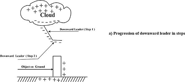


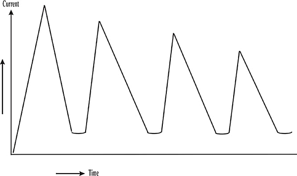


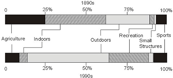
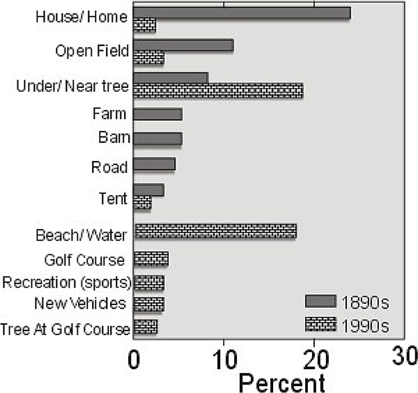

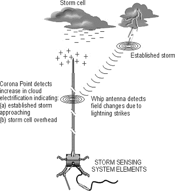


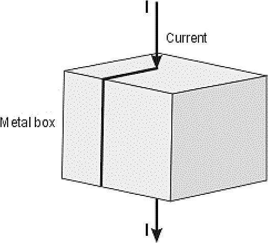
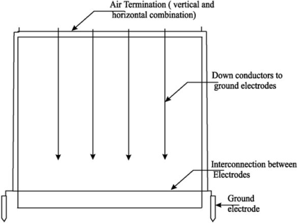


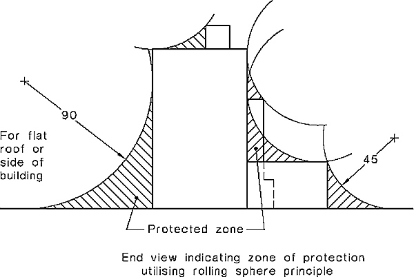
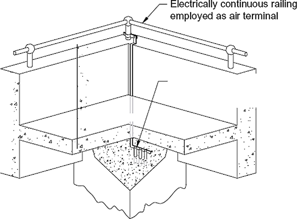


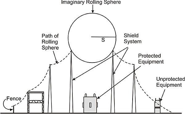
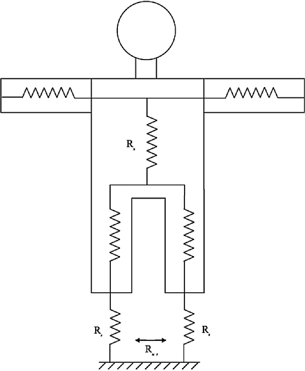


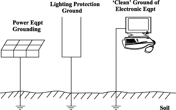


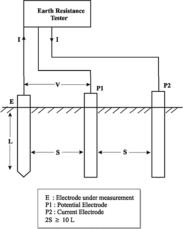
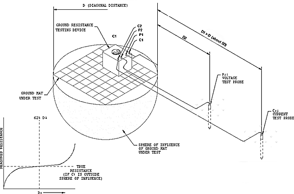

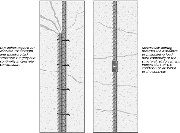


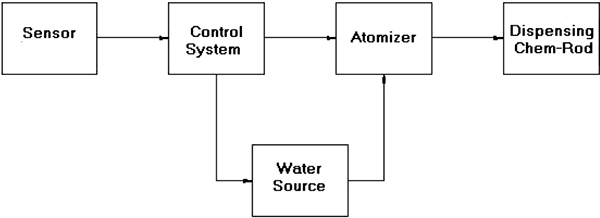


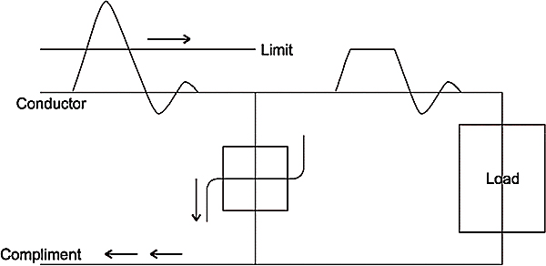


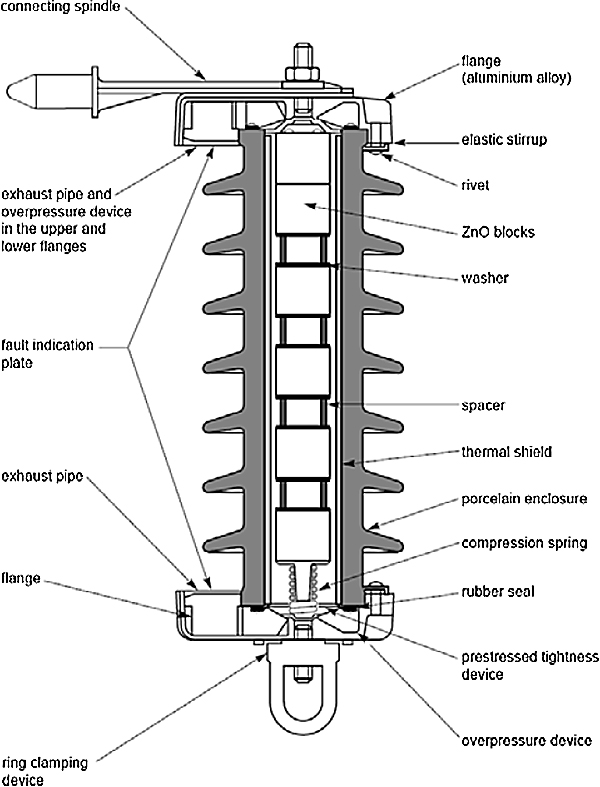
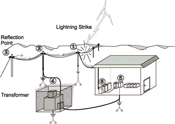


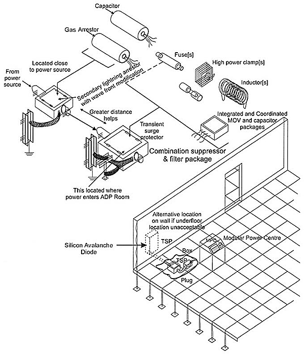
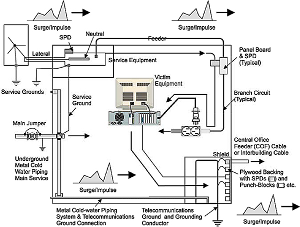


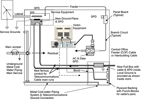


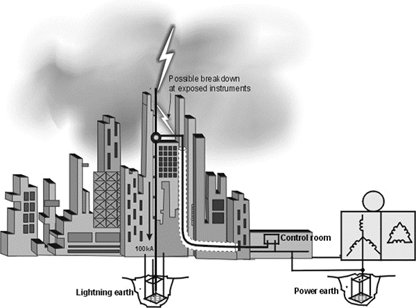


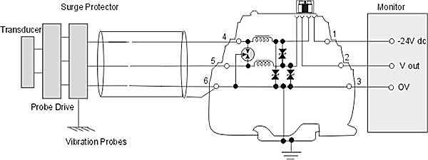
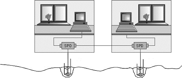
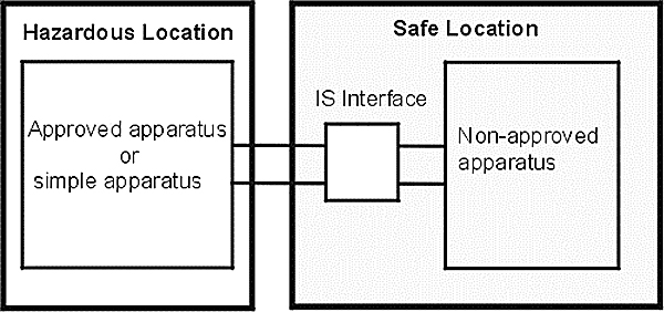


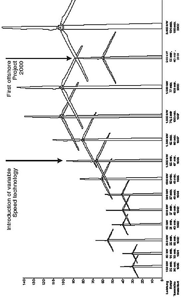


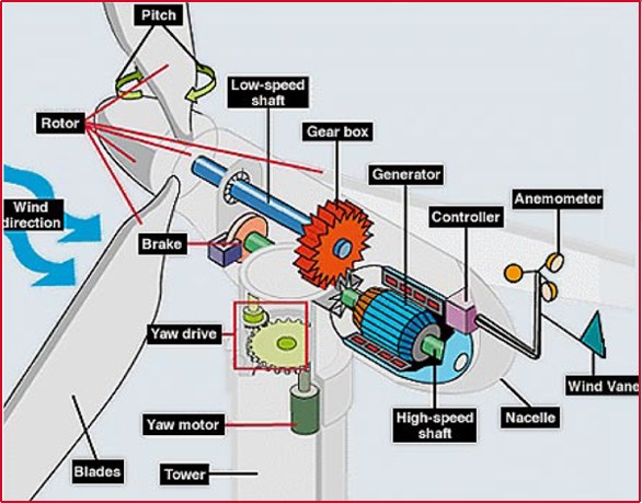
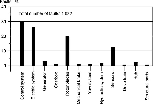


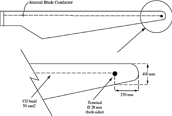
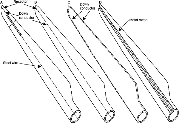
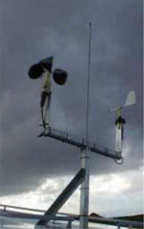


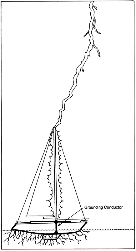
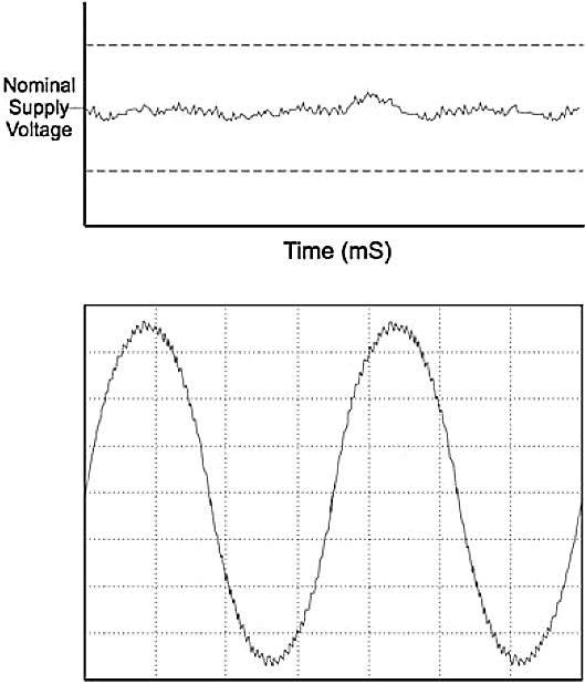
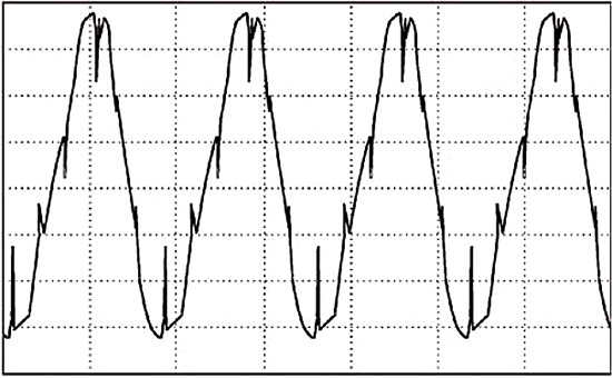


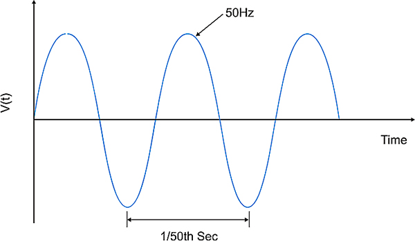
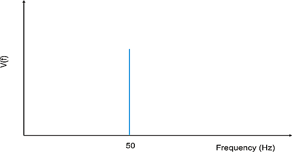


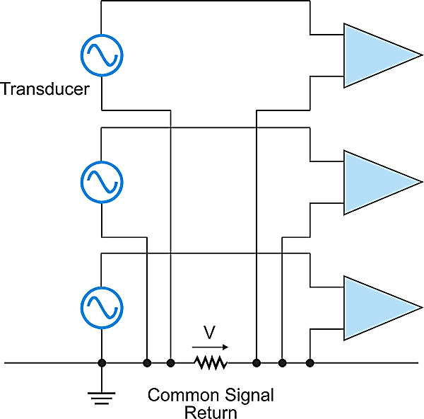


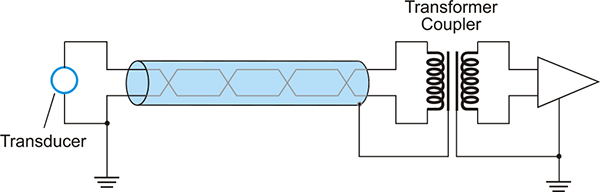
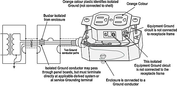


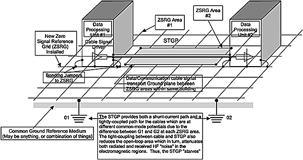
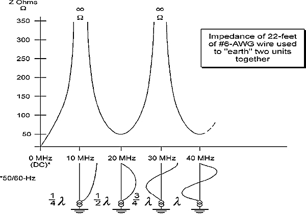


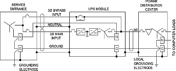

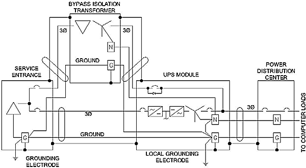
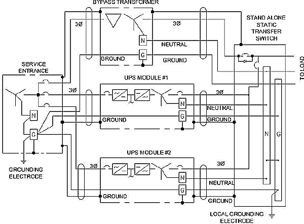
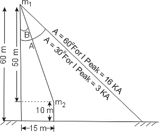


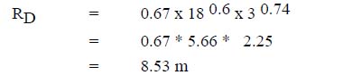


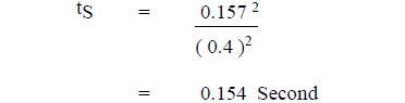


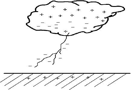


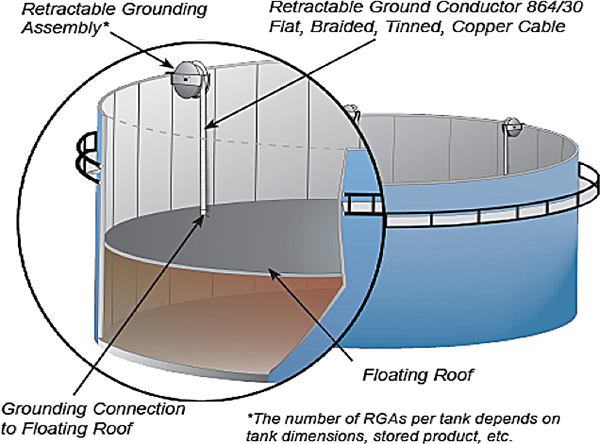


")


")


 & SCADA Systems")


")
")


")
